Note: Descriptions are shown in the official language in which they were submitted.
CA 02493905 2004-12-20
WO 2004/001380 PCT/US2003/019691
-1-
ELECTROCHEMILUMINESCENCE FLOW CELL
AND FLOW CELL COMPONENTS
Related Application
This patent application claims benefit from United States Provisional Patent
Application No. 60/390,816, entitled: "Electrochemiluminescence Flow Cell and
Flow Cell Components", filed June 20, 2002.
Field of the Invention
The present invention relates generally to the field of
electrochemiluminescence (ECL), to ECL-based devices and, more particularly,
to
ECL electrodes. The invention also relates to systems, apparatus, assay cells
and flow
cells that incorporate ECL electrodes and to methods for conducting ECL-based
measurements and assays. The invention also relates to electrochemical assay
systems that incorporate an apparatus, assay cell, flow cell or electrode of
the present
invention, as well as to assay methods utilizing same.
Background of the Invention
Many ECL-based instruments for conducting biological assays and medical
tests utilize a reusable flow cell. For an example of such a system, see U.S.
Patent
No. 6,200,531. The performance of such flow cells are affected by many factors
including, for example, background signal noise, signal drift, electrode
etching and
carryover. The presence of background signal noise reduces the measurement
sensitivity of an ECL-based flow cell. The development of ECL measurement
signal
drift over time decreases the reproducibility of assay measurements. The
deterioration of ECL electrodes due to etching reduces the efficiency of ECL
generation. "Carryover," the accumulation of residuals in the flow cell from
prior
measurements, reduces the reliability of ECL measurements.
An improved flow cell and flow cell components are needed to provide
improved performance and increased operational lifetime for ECL-based
apparatus.
CA 02493905 2004-12-20
WO 2004/001380 PCT/US2003/019691
-2-
Summary of the Invention
An assay apparatus, assay cell or flow cell for conducting electrochemical or
ECL assays includes at least one electrode. In an ECL device, the electrode is
capable
of participating in the generation of ECL. Preferably, an ECL device comprises
working and counter electrodes capable of inducing ECL from Ru(bpy)3 in the
presence of tripropylamine (TPA). The working and/or counter electrodes may be
made of materials other than pure platinum or pure gold; preferably one or
more of
the electrodes are made of a platinum alloy, rhodium, a rhodium alloy,
iridium, or an
iridium alloy. Electrodes made of such materials have demonstrated improved
properties as compared to conventional Pt electrodes. An electrode may
incorporate a
field extending element to provide additional pathways for current to flow for
improved ECL generation and application of electrical energy. Also, the
electrodes
may be operated so that the electrode closest to the light detector is
maintained at a
constant potential or at a potential that is constant relative to a voltage of
the
photodetector. Advantageously, the disclosed improvements increase apparatus
operational lifetime and improve performance in both ECL and electrochemical
applications. The invention also relates to assay systems that incorporate the
apparatus, assay cell or flow cell of the present invention and to assay
methods that
utilize the apparatus, assay cell or flow cell of the present invention.
It is an object of the present invention to provide assay apparatus and
methodologies for overcoming the deficiencies of the prior art.
It is an object of the present invention to provide apparatus for ECL or
electrochemical assays which are more robust with increased operational
lifetime and
improved performance as compared to the prior art.
2,5 It is another object of the present invention to provide improved
materials for
electrodes for ECL apparatus.
It is a further object of the present invention to provide electrode
configurations for improving the application of electrical energy to an assay
sample.
It is a further object of the present invention to provide electrode
configurations for conducting current in patterns that improve ECL generation.
CA 02493905 2004-12-20
WO 2004/001380 PCT/US2003/019691
-3-
It is still a further object of the present invention to provide methodologies
for
conducting assays using electrode materials and electrode configurations of
the
present invention.
It is still further an object of the present invention to provide apparatus
and
methodologies for operation of an ECL apparatus to improve ECL detection
sensitivity and ECL measurement accuracy.
One aspect of the invention relates to an assay cell, preferably an ECL cell,
most preferably an ECL flow cell, comprising a first electrode comprising an
alloy
capable of inducing electrochemiluminescence, preferably a platinum alloy
having a
predetermined weight percent of platinum and a predetermined weight percent of
a
different alloy component (preferably, a transition element, more preferably,
Ni, Pd,
Co, Fe, Ru, Os, Cr, Mo, Zr, Nb, Ir, Rh, or W, even more preferably Rh or Ir,
most
preferably Rh or Ir at a weight percentage between 1-80%). Preferably, the ECL
cell
also comprises a second electrode, an optical detection window and/or,
optionally, a
reference electrode. More preferably, the assay cell further comprises a cell
chamber
that comprises a first surface that supports the first electrode (the first
electrode
preferably being configured to act as a working electrode in an ECL
measurement)
and an opposing second surface that supports the second electrode (the second
electrode preferably being configured to act as a counter electrode) and that
has a
transparent zone that, preferably, forms at least part of the optical
detection window.
The invention also relates to an apparatus, preferably an ECL apparatus,
comprising
said assay cell and, optionally, a light detector.
Another aspect of the invention relates to an ECL apparatus comprising a first
electrode (preferably configured to act as a working electrode in an ECL
measurement) comprising an alloy capable of inducing electrochemiluminescence,
preferably a platinum alloy having a predetermined weight percent of platinum
and a
predetermined weight percent of a different alloy component (preferably, a
transition
element, more preferably, Ni, Pd, Co, Fe, Ru, Os, Cr, Mo, Zr, Nb, Ir, Rh, or
W, even
more preferably Rh or Ir, most preferably Rh or Ir at a weight percentage
between 1-
80%). Preferably, the apparatus also comprises a second electrode (preferably
configured to act as a counter electrode) and, optionally, a reference
electrode. More
preferably, the assay cell further comprises (e.g., in a cell chamber) a first
surface that
CA 02493905 2004-12-20
WO 2004/001380 PCT/US2003/019691
-4-
supports the first electrode and an opposing second surface that supports the
second
electrode and that has a transparent zone. The invention also may comprise a
light
detector that is, preferably, in optical registration with said first
electrode and said
transparent zone.
Another aspect of the invention relates to an assay cell, preferably an ECL
cell, most preferably an ECL flow cell, comprising a first electrode that is
capable of
inducing electrochemiluminescence and comprising a metal electrode material
other
than pure Pt and Au and, preferably, comprising rhodium, a rhodium alloy,
iridium or
an iridium alloy. The first electrode, preferably, having a predetermined
weight
percent of rhodium or iridium and, optionally, a predetermined weight percent
of a
different alloy component (preferably, a transition element, more preferably,
Ni, Pd,
Co, Fe, Ru, Os, Cr, Mo, Zr, Nb, Ir, Pt, or W, most preferably Pt). Preferably,
the ECL
cell also comprises a second electrode, an optical detection window and/or,
optionally, a reference electrode. More preferably, the assay cell further
comprises a
cell chamber that comprises a first surface that supports the first electrode
(the first
electrode preferably being configured to act as a working electrode in an ECL
measurement) and an opposing second surface that supports the second electrode
(the
second electrode preferably being configured to act as a counter electrode)
and that
has a transparent zone that, preferably, forms at least part of the optical
detection
window. The invention also relates to an apparatus, preferably an ECL
apparatus,
comprising said assay cell and, optionally, a light detector.
Another aspect of the invention relates to an ECL apparatus comprising a first
electrode (preferably configured to act as a working electrode in an ECL
measurement) comprising a metal electrode material other than pure Pt or Au
(preferably rhodium or a rhodium alloy), the first electrode being capable of
inducing
electrochemiluminescence. Preferably, the first electrode comprises an alloy
having a
predetermined weight percent of rhodium and, optionally, a predetermined
weight
percent of a different alloy component (preferably, a transition element, more
preferably, Ni, Pd, Co, Fe, Ru, Os, Cr, Mo, Zr, Nb, Ir, Pt, or W, most
preferably Pt).
Preferably, the apparatus also comprises a second electrode (preferably
configured to
act as a counter electrode) and, optionally, a reference electrode. More
preferably, the
assay cell further comprises (e.g., in a cell chamber) a first surface that
supports the
CA 02493905 2004-12-20
WO 2004/001380 PCT/US2003/019691
-S-
first electrode and an opposing second surface that supports the second
electrode and
that has a transparent zone. The invention also may comprise a light detector
that is,
preferably, in optical registration with said first electrode and said
transparent zone.
Another aspect of the invention relates to an assay cell, preferably an ECL
cell, most preferably an ECL flow cell, the flow cell comprising a working
electrode
capable of inducing electrochemiluminescence and a counter electrode
comprising a
metal other than pure Pt or Au (preferably, iridium or an iridium alloy, most
preferably, a Pt-Ir alloy or, alternatively, rhodium or a rhodium alloy, most
preferably
a Pt-Rh alloy) and, preferably, an optical detection window. The working
electrode
may comprise the same electrode material as the counter electrode or may be
different
(e.g., Pt, a Pt alloy, Ir, a Pt-Ir alloy, Rh, a Pt-Rh alloy, etc.).
Another aspect of the invention relates to an ECL apparatus comprising a
working electrode capable of inducing electrochemiluminescence, a counter
electrode
comprising a metal other than pure Pt or Au (preferably, iridium or an iridium
alloy,
most preferably a Pt-Ir alloy or, alternatively, rhodium or a rhodium alloy,
most
preferably a Pt-Rh alloy), and a light detector. The working electrode may
comprise
the same electrode material as the counter electrode or may be different
(e.g., Pt, a Pt
alloy, Ir, a Pt-Ir alloy, Rh, a Pt-Rh alloy, etc.).
Another aspect of the invention relates to an assay cell, preferably an ECL
cell, most preferably an ECL flow cell, comprising a working electrode and a
counter
electrode having at least one field extending element. The cell, preferably,
further
comprises a first surface that supports the working electrode and an opposing
second
surface that supports the counter electrode, the second surface having a
transparent
zone. Most preferably, the field extending element extends into or across the
transparent zone.
Another aspect of the invention relates to an ECL apparatus comprising a
working electrode and a counter electrode having at least one field extending
element.
The apparatus, preferably, also comprises a first surface that supports the
working
electrode, an opposing second surface that supports the counter electrode and
has a
transparent zone; and a light detector, wherein the light detector, the
working
electrode and the counter electrode are in optical registration. Most
preferably, the
field extending element extends into or across the transparent zone.
CA 02493905 2004-12-20
WO 2004/001380 PCT/US2003/019691
-6-
Another aspect of the invention relates to an ECL cell, preferably an ECL flow
cell, comprising a working electrode, a counter electrode, a first surface
that supports
the working electrode, and a second surface that supports the counter
electrode and
that has a transparent zone, wherein the flow cell is adapted to maintain the
counter
electrode at a constant potential during an ECL measurement. The cell may
optionally comprise a reference electrode and/or a light detector.
Another aspect of the invention relates to an ECL apparatus comprising a
working electrode, a counter electrode, a first surface that supports the
working
electrode, a second surface that supports the counter electrode and that has a
transparent zone, and a light detector, wherein the working electrode, the
transparent
zone and the light detector are in optical registration with each other. The
ECL
apparatus further comprises a source of electrical energy for inducing ECL
(such as a
voltage source, a current source or, preferably, a potentiostat) that is
adapted to
maintain said counter electrode at a constant potential (preferably, ground)
or to
maintain said counter electrode at a potential that does not vary relative to
said light
detector. The ECL apparatus may also comprise a reference electrode and the
source
of electrical energy may comprise a potentiostat and, optionally, a voltage
subtraction
circuit that outputs a voltage representative of the difference in potential
between the
working and reference electrodes.
Brief Description of the Drawings
Figures lA and 1B show views of a flow cell for conducting ECL
measurements.
Figures 2A-2J illustrate embodiments of counter electrodes according to
embodiments of the invention.
Figure 3 is a diagram of a system for conducting ECL measurements.
Figures 4A-4F are photographs of electrodes from ECL flow cells illustrating
the effects of electrode etching.
Figure 5 is a graph showing ECL signal drift in a flow cell having a Pt-10%Ir
electrode.
Figure 6 is a graph showing ECL signal drift in a flow cell having a Pt
electrode.
CA 02493905 2004-12-20
WO 2004/001380 PCT/US2003/019691
- 'j _
Figures 7A and 7B are graphs showing ECL signal drift that resulted from
repeated decontamination of ECL flow cells with a 25% solution of 5.25% bleach
in a
flow cell having a Pt-10%Ir electrode (Figure 7A) and in a flow cell having a
Pt
electrode (Figure 7B).
Figure 8 is a graph of cell potentials measured during cleaning procedures in
flow cells having Pt or Ir counter electrodes.
Figure 9 is a graph showing ECL signal drift in a flow cell having a Pt
working electrode and an Ir counter electrode.
Figure 10 is a graph in which electrochemical current is plotted as a function
of the electrochemical potential at the working electrode and shows the
influence of
electrode composition on the oxidation of water at a pH of 6.8.
Figure 11 is a graph in which electrochemical current is plotted as a function
of the electrochemical potential at the working electrode and shows the
influence of
electrode composition on the oxidation of tripropylamine (TPA). Oxidizing
potentials
were applied at metal electrodes in the presence of a phosphate-based buffer.
Figures 12A-12C are graphs of current density vs. electrode potential and
illustrate the influence of Ir content on the ability of Pt alloy electrodes
to oxidize
phosphate-buffered water, TPA and Ru(II)(bpy)3 where bpy is 2,2'-bipyridine.
Results are shown for platinum (Figure 12A), Pt-10%Ir (Figure 12B) and Pt-
30%Ir
(Figure 12C) electrodes.
Figures 13A-13D are graphs of current density vs. electrode potential and
illustrate the influence of Rh content on the ability of Pt alloy electrodes
to oxidize
phosphate-buffered water, TPA and Ru(II)(bpy)3. Results are shown for Pt-10%Rh
(Figure 13A), Pt-20%Rh (Figure 13B), Pt-30%Rh (Figure 13C) and Rh (Figure 13D)
electrodes.
Figure 14 is a graph of current density vs. electrode potential and
illustrates
the ability of a Pt-8%W alloy electrode to oxidize phosphate-buffered water,
TPA and
Ru(II)(bpy)3.
Figure 15 is a graph showing ECL signal generated from Ru(bpy)3 in TPA
Assay Buffer as a function of the applied electrochemical potential at
electrodes of
different compositions.
CA 02493905 2004-12-20
WO 2004/001380 PCT/US2003/019691
_$_
Figures 16 is a diagram of an ECL apparatus according to an embodiment of
the invention.
Detailed Description
All values of electrochemical potentials are relative to the Ag/AgCI reference
unless otherwise indicated.
An assay apparatus, assay cell or flow cell for conducting electrochemical or
ECL assays according to the present invention includes at least one electrode.
The
electrode may comprise a material other than pure platinum or pure gold that
demonstrates utility in electrochemical or ECL assays. In addition, or
alternatively,
an electrode may incorporate one or more field extending elements to provide
additional pathways for current to flow facilitating the improved application
of
electrical energy. Also, the electrode may be operated so that it is
maintained at a
constant potential or at a potential that is constant relative to a voltage of
a light
detector in or near the apparatus. The disclosed improvements increase
apparatus
operational lifetime and improve apparatus performance.
The invention includes improved electrodes for conducting ECL
measurements that have improved properties (including resistance to etching,
low
carryover, longer lifetime, lower currents, etc.) than conventional Pt
electrodes while,
preferably, producing comparable performance in ECL assays. The invention also
relates to ECL assay cells (and in particular ECL flow cells) that comprise
these
improved electrodes.
An ECL assay cell includes at least one electrode, and preferably both a
working electrode and a counter electrode, for inducing ECL-active materials
to
electrochemiluminesce. In addition, the ECL assay cell provides one or more
optical
paths for allowing the resultant ECL signal to reach a light detector. The
optical paths
may pass through one or more optical detection windows in the ECL assay cell.
Also,
ECL assay cells may include: reference electrodes to facilitate control of the
working
electrode with a potentiostat; a magnet device operable to reversibly collect
magnetizable particles (interchangeably referred to throughout as magnetic
beads) at
the surface of the working electrode; or an integrated light detector and
associated
optical elements and filters for collecting, processing, and detecting ECL
signals.
CA 02493905 2004-12-20
WO 2004/001380 PCT/US2003/019691
-9-
In an ECL device, an electrode is capable of participating in the generation
of
ECL. Preferably, an ECL device comprises working and counter electrodes
capable
of inducing ECL from Ru(bpy)3 in the presence of TPA, at least one of which is
not
made of pure platinum or pure gold. Preferably one or more of the electrodes
are
made of a platinum alloy, rhodium, a rhodium alloy, iridium, or an iridium
alloy. In
addition, or alternatively, an electrode may incorporate a field extending
element to
provide additional pathways for current to flow to facilitate improved ECL
generation
and improved application of electrical energy for other ECL device operations.
Also,
the electrodes may be operated so that the electrode closest to the light
detector is
maintained at a constant potential or at a potential that is constant relative
to a voltage
of the light detector.
In certain embodiments, induced ECL is detected by a light detector at a
distance, through one or more intervening layers of material. Such intervening
layers
constitute optical windows through which wavelengths of light of interest may
substantially pass. Also, such layers may be electrically conductive to shield
the light
detector from capacitive noise generated at the electrodes or elsewhere. Field
extending elements of the electrode of the present invention may extend in
part or
entirely across such optical windows.
The invention also relates to assay systems that incorporate the apparatus, an
assay cell or a flow cell of the present invention. Such systems preferably
further
include reagant-handling apparatus, assay reagants, sample-handling apparatus,
assay
samples and the like. Assay methods utilizing the apparatus, assay cell or
flow cell of
the present invention demonstrate improved performance.
ECL assay cells configured as flow cells, referred to herein as ECL flow
cells,
are particularly useful for systems that require reusable ECL assay cells.
U.S. Patent
No. 6,200,531 discloses examples of ECL flow cells and ECL apparatus
incorporating
such flow cells, and the entirety of said patent is hereby incorporated herein
by
reference (in particular, Figures 3A, 3B and 4A-4D and the accompanying
descriptions in the text). It should be noted that while the improved
electrodes of the
present invention will be described primarily in the context of their
implementation in
ECL flow cells, such electrodes may be readily implemented in "static" assay
cells
that do not have a "flow-through" configuration.
CA 02493905 2004-12-20
WO 2004/001380 PCT/US2003/019691
-10-
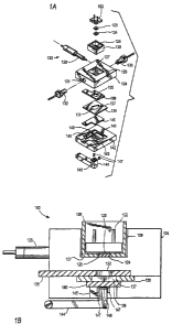
Figures lA and 1B illustrate exploded and cross-sectional views, respectively,
of one embodiment of an ECL flow cell 120. Flow cell 120 comprises a light
detector
122, an optical filter 123, a conductive window 124, an electrical shield 126
having an
opening 125, a reference electrode 128, fluid couplings 130 and 132, a cell
component
134 having an optical detection window 127, a counter electrode 136 having an
opening 133, a gasket 138 with an opening 137 that defines a portion of flow
cell
chamber 139, a working electrode 140, and a cell base 142. Optionally, shield
126
and window 124 may be made from one contiguous piece of material. Cell
component 134 receives fluid into the flow cell via fluid couplings 130 and
132. Base
142 has an opening 145, to accommodate magnet 146 on pivot arm 144, and a
magnet
detector 147.
Light detector 122 may be implemented as a photodiode, avalanche
photodiode, charge coupled device, CMOS sensor, photomultiplier tube, film, or
the
like. Alternatively, light detector 122 may comprise an array of light
detecting
devices, e.g., a photodiode array, a CCD array, a CMOS camera, or the like.
Preferably, light detector 122 includes a photodiode.
According to an embodiment of the present invention, an ECL apparatus
includes an ECL chamber at least partially defined by the surface of an
electrode,
preferably the working electrode, and the surface of a substantially
transparent
structure in the optical pathway between the electrode and the light detector.
Preferably, the two surfaces face each other. It is preferred that the
structure be a
support structure to which a second electrode, preferably the counter
electrode, is
attached in proximity to the first electrode. In an alternative embodiment,
the counter
electrode is not directly attached to the support structure and is preferably
held in a
location between the working electrode and the support structure. The second
electrode may partially define a perimeter of the transparent portion of the
structure,
via one or more openings, apertures, slots, infoldments, or the like.
Alternatively, the
second electrode is transparent (e.g., a counter electrode made of indium tin
oxide,
antimony tin oxide, or of a thin metal film that is thin enough (typically <
20 ~) to
be substantially transparent) so that the second electrode may cover the
transparent
portion of the structure surface without interfering with its ability to
transmit relevant
wavelengths of light.
CA 02493905 2004-12-20
WO 2004/001380 PCT/US2003/019691
-11-
The transparent portion of the structure is in optical registration with at
least a
portion of the surface of the working electrode so that ECL generated at that
surface
may be transmitted through the transparent portion to the light detector. For
example,
referring to Fig. 1B, the portion of component 134 that extends from window
124 to,
S or through, opening 133 is substantially transparent and chamber 139 is
partially
defined by a portion of the surface of component 134. Light detector 122 is in
optical
registration with the portion of working electrode 140 defined by opening 125
and
opening 133. Optionally, the light detector may be integrated into cell 120 or
remain
external thereto. As a further option, a surface of the light detector itself
may define
part of the ECL chamber.
A preferred assay apparatus for conducting ECL measurements with an ECL
flow cell includes an ECL flow cell, a source of electrical energy for
applying
electrical energy to the electrodes, a fluidic system for introducing samples
and
reagents to the flow cell, and electronic or computer controllers for
controlling the
apparatus, measuring and analyzing ECL signals and providing a user interface.
The
source of electrical energy is a voltage source, a current source, a
potentiostat or the
like. The fluidic system may include conventional pumps, valves, probes,
reagent
bottles and the like.
ECL apparatus of the present invention are preferably adapted to induce and
measure ECL from electrochemiluminescent organometallic complexes, more
preferably polypyridyl (e.g., bipyridine and phenanthroline-containing)
complexes in
particular of Ru and Os and, most preferably, from ECL species and labels that
comprise Ru(II)(bpy)3 and derivatives thereof. Such derivatives can include
substituted bipyridines, especially bipyridines that are substituted with
functional
groups that are used for linking the label to biomolecules. Preferably, the
apparatus
operates to induce and measure ECL using any available techniques to induce
ECL
from polypyridyl complexes of Ru and Os, for example, annihilation and
coreactant-
based techniques.
Preferably, ECL apparatus according to the present invention measures ECL
induced at oxidizing electrodes from the preferred ECL labels in the presence
of an
ECL coreactant, preferably a molecule that is oxidized to produce a strong
reductant,
more preferably a tertiary amine, more preferably a trialkylamine, and most
CA 02493905 2004-12-20
WO 2004/001380 PCT/US2003/019691
-12-
preferably tripropylamine (TPA). The coreactant is preferably comprised of an
ECL
assay buffer which may also include a pH buffering component. Especially
preferred
ECL assay buffers comprise TPA (preferably, at a concentration greater than or
equal
to 100 mM), and phosphate as a pH buffering component (preferably, at a
concentration greater than or equal to 100 mM and at a pH of 6.5-8.0).
Optionally, a
surfactant (e.g., a non-ionic surfactant such as Triton X-100, Tween 20 or
Thesit), a
preservative (e.g., azide, an isothiazolone such as 2-methyl-3(2H)-
isothiazolone
(MIT) or 5-chloro-2-methyl-3(2H)-isothiazolone (CIT) or an oxazolidine such as
BIOBAN CS-1135) or an additional electrolyte (e.g., sodium chloride) may be
utilized in the ECL assay buffer.
The mechanism for the generation of ECL from Ru(II)(bpy)3 and related ECL-
active species at oxidizing electrodes in the presence of ECL coreactants is
believed
to involve: (i) oxidation of the ECL-active species to produce an oxidized ECL-
active
species; (ii) oxidation of the coreactant to produce a strong reluctant; (iii)
electron
transfer from the strong reluctant to the oxidized ECL-active species in a
highly
energetic reaction that regenerates the ECL-active species to its original
oxidation
state but in an excited electronic state; and (iv) emission of a photon to
regenerate the
ECL-active species to its original electronic (ground) state. This proposed
mechanism
is illustrated for Ru(II)(bpy)3 and TPA below:
Ru(II)(bpy)3 - a Ru(III)(bpy)s
Pr~N~CH3 ~ Pr N~CH3 ~ PrZN~CH3
Ru(III)(bpY)3 -I- PrZN~CH3 ~ Ru(II)(bpY)3 -I- Pr2N~CH3
Ru(11)(bpy)3 --->- Ru(II)(bpy)3 + light
In a preferred operation, a sample comprising an ECL-active species and an
ECL coreactant (e.g., in an ECL assay buffer) are introduced into an ECL assay
cell,
preferably an ECL flow cell. The working electrode is held at a pre-operative
potential (POP) during the introduction of the sample (preferred POPS being
between
-0.8 and 0.8 V vs. Ag/AgCI, more preferably between -0.6 and 0.6 V). An
electrochemical potential is then applied to the working electrode (e.g., by
applying
CA 02493905 2004-12-20
WO 2004/001380 PCT/US2003/019691
-13-
an electrical potential across the working and counter electrodes in the ECL
assay
cell, using a potentiostat to achieve a predetermined electrochemical
potential at the
working electrode relative to a reference electrode) to induce the ECL-active
species
to electrochemiluminesce. The applied potential oxidizes the ECL-active
species and
the coreactant at the electrode but avoids substantial oxidation of water
(especially
preferred ECL excitation potentials range from 1.0 -1.8 V, more preferably
from 1
-1.5 V and most preferably 1.2 -1.3 V vs. Ag/AgCI). A variety of different
electrical waveforms may be used to generate the ECL excitation potential;
preferred
waveforms are step or ramp waveforms or combinations thereof. The emission of
ECL is measured with a light detector.
Subsequent to the generation and measurement of ECL from the sample, the
assay cell is preferably cleaned and prepared for measuring a new sample. In
one
embodiment, a cleaning solution (typically a basic solution comprising a
detergent) is
introduced and a series of cleaning potentials are applied. It has been found
that it is
especially advantageous for cleaning to use oxidizing or reducing potentials
that are
sufficient to generate oxygen or hydrogen gas on the electrode surfaces.
Preferred
cleaning potentials include oxidizing potentials of at least 1.5 V, more
preferably at
least 2.0 V, and most preferably approximately 2.0 V; or reducing
potentials'of at
least -1.0 V, more preferably at least -1.5 V, and most preferably
approximately -1.5
V. In a particularly preferred cleaning process, the reducing and oxidizing
potentials
described above are alternated. It may also be desirable to introduce bubbles
of air
during the cleaning process.
In a preferred cleaning operation, prior to introduction of the sample, the
cleaning solution is flushed out of the assay cell by introducing ECL assay
buffer. A
series of "prepare" potentials are applied to the electrodes during this
process.
"Prepare" potentials may include alternating step potentials of less magnitude
than the
cleaning potentials, e.g., oxidizing potentials of more than 0.5 V, more
preferably
approximately 0.75 V, and reducing potentials of at least -0.3 V, preferably
approximately -O.SV.
According to some embodiments ofthe invention, assays are conducted
utilizing magnetizable particles as solid phase supports for ECL assay
constituents.
Such measurements may involve the measurement of ECL emitted by labels bound
to
CA 02493905 2004-12-20
WO 2004/001380 PCT/US2003/019691
-14-
the surface of the particles, e.g., ECL-labeled biomolecules that are bound
through
biospecific interactions to binding reagents on the surface of the particles.
When
conducting measurements for assays employing magnetizable particles, a
magnetic
field is applied near the surface of the working electrode prior to or during
the
introduction of the sample to collect the magnetizable particles on the
surface of the
working electrode. For example, with reference to Fig. 1B, pivot arm 144 of
cell 120
is pivoted to raise magnet 146 near working electrode 140.
The collected particles are, optionally, washed by flowing ECL assay buffer
through the flow cell. ECL is then induced and measured as described above.
Preferably, the magnetic field is removed prior to cleaning and preparing the
cell for
another measurement.
Electrode Materials
During operation of an ECL flow cell incorporating working and counter
electrodes made of pure platinum (Pt), both electrodes may deteriorate
significantly
over time due to etching of the exposed surfaces of the electrodes. Such
etching is a
major limiting factor upon the operational lifetime of a flow cell. Flow cells
have also
been observed, in some configurations, to exhibit a downward drift in detected
ECL
signal and a rise in background signal over the lifetime of the flow cell.
Under certain
circumstances, the downward drift in signal has been observed to be as much as
10%
of the initial signal levels over the course of approximately 2900
measurements.
Applicants hypothesize that this downward drift is related to the etching
process.
To compensate for such drift, an ECL instrument will need to be recalibrated,
have its measurements normalized over the lifetime of the flow cell or have
the
electrodes) or flow cell replaced at regular intervals.
Test data indicates that oxidation of the electrode is the primary cause of
etching and it is postulated that a significant percentage of the electrode
etching
observed occurs during the processes of cleaning and regenerating the
electrodes
between measurements. In particular, in instruments for conducting magnetic
bead-
based assays, high electric potentials are used to clean the beads from the
surface of
the working electrode. The application of high potentials during a cleaning
cycle
causes platinum oxides to form on the surface of the electrodes. These
platinum
CA 02493905 2004-12-20
WO 2004/001380 PCT/US2003/019691
-15-
oxides are loosely bound to the surface and are believed to be released into
solution
and washed away by cleaning reagent during the cleaning cycle.
Moreover, it has been observed that the Pt dissolved by oxidation may
subsequently accumulate or otherwise deposit at locations within the flow
cell. When
the platinum oxides collect at locations in the optical path between the
working
electrode and the light detector, e.g., on the optical window, a reduction in
light
collection efficiency results. Applicants hypothesize that such deposition is
one of the
causes of ECL signal drift.
For certain flow cell based ECL instruments, optimization of the cleaning step
after an ECL measurement may be more important than the measurement step
itself
for ensuring reproducible ECL measurements. In embodiments that employ
magnetizable beads, the cleaning cycle preferably should remove all "used"
beads
from the working electrode to ensure that there is no "carryover" of signal
from one
assay to the next.
According to one cleaning process, the voltage applied to the working
electrode is pulsed between a reducing voltage and an oxidizing voltage.
Preferably,
the reducing voltage is low enough to reduce water to create hydrogen gas and
the
oxidizing voltage is high enough to oxidize platinum and oxidize water to
create
oxygen gas. In a particularly preferred ECL-based flow cell cleaning sequence,
the
reducing voltage is -1.5 V and the oxidizing voltage is 2 V (vs. Ag/AgCI). It
is
believed that both the generation of such gases and the oxidation of Pt
resulting from
such a cleaning cycle assist in removing beads from the working electrode.
In a cleaning cycle, a cleaning reagent (preferably an aqueous solution
comprising a detergent and, optionally, a base such as a hydroxide salt -
e.g., an alkali
metal hydroxide such as sodium hydroxide or potassium hydroxide - and having a
basic pH, preferably greater or equal to 10) may be flowed through the flow
cell to-
flush any solid supports, e.g., magnetizable beads, from the surface of the
working
electrode. To enhance cleaning effectiveness, air may be introduced during the
cleaning cycle, e.g., by introducing bubbles.
In one preferred embodiment, one or both of the working and counter
electrodes are fabricated of an electrode material that has an increased
oxidation
resistance and is, therefore, less prone to etching, to increase the effective
operational
CA 02493905 2004-12-20
WO 2004/001380 PCT/US2003/019691
-16-
lifetime of the electrode(s), reduce signal drift and reduce carryover.
Electrode
materials suitable for use as the working electrode in an ECL-based flow cell
preferably exhibit electrochemical characteristics similar to platinum.
Specifically,
preferred materials oxidize TPA and Ru(bpy)3 at potentials that are lower than
the
potential for the oxidation of water at that electrode (most preferably, this
condition
being met for solutions having pH values between 6.5 and 8).
According to a method of the present invention, an ECL label (preferably a
luminescent organometallic complex of Ru or Os, more preferably, Ru(bpy)3 or a
derivative thereof) is induced to electrochemiluminesce in the presence of an
ECL
coreactant (preferably, a tertiary amine, most preferably, TPA) by applying a
potential
to a working electrode, wherein: (i) the working electrode and, optionally,
the counter
electrode is a metal electrode other than pure Pt or Au; (ii) said potential
is sufficient
to oxidize the ECL label and the ECL coreactant; and (iii) the applied
potential
produces a current density from the oxidation of the coreactant that is at
least equal
(more preferably at least two times, even more preferably at least 5 times,
even more
preferably at least 10 times) the current density from the oxidation of water.
In another embodiment of the present invention, the working and, optionally,
the counter electrode, of an ECL flow cell comprises a metal or metal alloy,
other
than pure platinum or gold, that at an electrochemical potential of 1.3 V vs.
Ag/AgCI -
- approximately the oxidation potential of Ru(II)(bpy)3 -- exhibits a current
density
during the oxidation of water of less than 5 mA/cm2; preferably in water
comprising
electrolytes at a pH of 6.5-8, more preferably in a phosphate-buffered aqueous
solution having a pH of 6.5-8.0; and most preferably in a solution comprising
200-400
mM KH2P04, 50-200 mM NaCI, surfactant and sufficient I~OH to adjust the pH to
6.6-6.8.
In another embodiment of the present invention, the working and, optionally,
the counter electrode, of an ECL flow cell comprises a metal or metal alloy,
other
than pure platinum or gold, that oxidizes TPA more readily than water.
Preferably,
this condition is met at an electrochemical potential at which Ru(II)(bpy)3 is
oxidized,
most preferably 1.3 V. In one preferred embodiment, the ratio of the
electrochemical
currents measured at the electrode at a potential of 1.3 V for 150 mM TPA in
phosphate buffer at a pH of 6.5-8.0 (most preferably, 150 mM TPA, 50-200 mM
CA 02493905 2004-12-20
WO 2004/001380 PCT/US2003/019691
-17-
NaCI, 200-400 mM phosphate, and surfactant, at a pH of 6.6-6.8) to the
electrochemical current measured in an analogous buffer that does not contain
TPA
(e.g., the same buffer solution at the same pH with TPA replaced by an
appropriate
pH adjuster) is at least one, more preferably at least two, more preferably at
least 5,
and most preferably at least 10.
According to an embodiment of the present invention, certain Pt alloys have
been identified as suitable replacements for Pt working electrodes or counter
electrodes in ECL flow cells. Surprisingly, it has been discovered that alloys
of
transition elements with Pt have electrochemical properties very similar to Pt
but have
advantages over pure Pt when used in ECL devices. These advantages have been
found to include improved resistance to electrochemical etching, reduced drift
in ECL
signal, reduced carryover and longer electrode operational lifetime.
Preferably, the Pt
alloys comprise Pt combined with a second transition element that is present
at a
weight percentage of 1-50%, more preferably 5-SO%, more preferably 10-30%, and
most preferably approximately 10%. Suitable alloys for ECL electrodes are
alloys of
Pt with Ni, Pd, Co, Fe, Ru, Os, Cr, Mo, Zr, Nb, Ir, Rh, or W; more preferably,
alloys
of Pt with Ir, Rh or W; and, most preferably, alloys of Pt with Ir.
In one preferred embodiment, an ECL electrode is formed of a Pt-Ir alloy
wherein the weight percent of iridium in the alloy is 1-50%, more preferably 5-
50%,
more preferably 10-50%, even more preferably 10-30%, and even more preferably
approximately 10%.
In another preferred embodiment, an ECL electrode is formed of a Pt-Rh alloy
wherein the weight percent of rhodium in the alloy is 1-50%, more preferably 5-
50%,
more preferably 10-50%, even more preferably 10-30%, and even more preferably
approximately 20%.
According to another embodiment of the invention, an electrode of an ECL
assay cell comprises, consists essentially of or consists of a transition
element other
than pure Pt or Au, preferably Ni, Pd, Co, Fe, Ru, Os, Cr, Mo, Zr, Nb, Ir, Rh
or W;
more preferably, Rh or Ir; and most preferably, Ir.
According to another embodiment of the invention, the counter electrode of an
ECL assay cell comprises an alloy of Pt and a transition element, the weight
percentage of the transition element being, preferably, 1-99%, more preferably
5-
CA 02493905 2004-12-20
WO 2004/001380 PCT/US2003/019691
-18-
50%, more preferably 5-30%, and most preferably 10-30%. The remainder of the
alloy may be substantially Pt or it may include an additional component as
well. The
transition element is preferably Ni, Pd, Co, Fe, Ru, Os, Cr, Mo, Zr, Nb, Ir,
Rh or W;
more preferably, Rh or Ir; and most preferably, Ir. In an alternate preferred
embodiment, the working electrode is Au or, preferably, Pt. In another
alternate
preferred embodiment, the working electrode is made from a Pt alloy,
preferably a Pt-
Ir alloy. In another alternate preferred embodiment, the working electrode is
a pure
transition element other than Pt or Au, e.g., Rh.
According to another embodiment of the invention, the counter electrode of an
ECL assay cell is formed of an alloy that comprises, consists essentially of,
or consists
of Pt and Ir. The weight percentage of Ir is, preferably, 1-99%, more
preferably S-
SO%, more preferably 5-30%, and most preferably 10-30%. In one preferred
embodiment, the working electrode is Au or, preferably, Pt.
In another preferred embodiment, the working electrode is formed of a Pt
alloy, preferably a Pt-Ir alloy (most preferably, the same alloy as comprises
the
counter electrode). In another preferred embodiment, the working electrode is
a pure
transition element other than Pt or Au, e.g., Rh.
According to another embodiment of the invention, the counter electrode of an
ECL assay cell comprises an alloy of Ir and a transition element, the weight
percentage of the transition element being, preferably, 1-99%, more preferably
5-
50%, more preferably 5-30%, and most preferably 10-30%. The remainder of the
alloy may be substantially Ir or it may include an additional component as
well. The
transition element is preferably Ni, Pd, Co, Fe, Ru, Os, Cr, Mo, Zr, Nb, Rh
and W. In
an alternate preferred embodiment, the working electrode is Au or, preferably,
Pt. In
another alternate preferred embodiment, the working electrode is a made from a
Pt
alloy, preferably a Pt-Ir alloy. In another alternate preferred embodiment,
the
working electrode is a pure transition element other than Pt or Au, e.g., Rh.
In still further alternative embodiments, the working electrode of an ECL
assay cell comprises an alloy of Ir or Rh and a transition element, the weight
percentage of the transition element being, preferably, 1-99%, more preferably
5-
50%, more preferably 5-30%, and most preferably 10-30%.
CA 02493905 2004-12-20
WO 2004/001380 PCT/US2003/019691
-19-
According to another embodiment of the invention, the counter electrode of an
ECL assay cell comprises an alloy of Rh and a transition element, the weight
percentage of the transition element being, preferably, 1-99%, more preferably
5-
50%, more preferably 5-30%, and most preferably 10-30%. The remainder of the
alloy may be substantially Rh or it may include an additional component as
well. The
transition element is preferably Ni, Pd, Co, Fe, Ru, Os, Cr, Mo, Zr, Nb, Ir,
or W; most
preferably, Ir. In an alternate preferred embodiment, the working electrode is
Au or,
preferably, Pt. In another alternate preferred embodiment, the working
electrode is a
made from a Pt alloy, preferably a Pt-Ir alloy. In another alternate preferred
embodiment, the working electrode is a pure transition element other than Pt
or Au,
e.g., Rh.
Advantageously, the counter electrode in an ECL cell has over-potentials for
the oxidation and/or reduction of water that are less than that of Pt
(preferably, by 50
mV or more, more preferably by 100 mV or more, most preferably by 200 mV or
more). Such reductions in over-potential will be directly translated into
lower cell
potentials during cell cleaning.
The working and counter electrodes are preferably generally planar and may
take a variety of different forms including thin films, sheets, foils, wires,
screens,
meshes, or the like. Thin films may be made by conventional methods including
those used in the manufacture of circuit boards and microelectronics, e.g., by
deposition of the film on a substrate via evaporation, chemical vapor
deposition,
sputtering, screen printing, electrodeposition, electroless deposition and the
like. The
electrodes may be patterned, configured or given a specific shape or geometry
via
patterned deposition, molding, lithography, machining, electroforming, laser
ablation,
patterned etching (e.g., reactive ion etching), and the like. The electrodes
of the
invention may be made of metal or a metal alloy. In alternate embodiments of
the
invention, they are composite materials that comprise a metal or metal alloy.
Electrode Geometry
According to an embodiment of the invention, the counter electrode is
configured with one or more field extending elements (e.g., electrode
projections) that
extend into or across the optical path of the light detector but leave
openings or
CA 02493905 2004-12-20
WO 2004/001380 PCT/US2003/019691
-20-
substantially transparent areas in the counter electrode through which light
is
transmitted. These field extending elements, by extending into or across the
optical
path of the light detector decreases the amount of light incident upon the
light detector
(preferably, by less than 50%, more preferably less than 25%, and most
preferably
less than i 0%) but, advantageously, may establish a substantially even
distribution of
current across the working electrode (e.g., during an ECL measurement or
cleaning
cycle) by decreasing the distance that current must travel through solution.
Preferably, the maximum distance between a point on the surface of the working
electrode that is in optical registration with the light detector and the
point on the
surface of the counter electrode closest thereto is less than 4 times the
distance
between the working electrode and the counter electrode, hereinafter the
"height of
the cell," more preferably less than 2.5 times the height of the cell, even
more
preferably less than 2.0 times the height of the cell, and most preferably
less than 1.5
times the height of the cell. This ratio is referred to herein as the "current
path aspect
ratio." For purposes of illustration, the height of cell 150 in Fig. 1B is
equal to the
thickness of gasket 13 8.
Working electrode 140 in Figures lA and 1B has (i) a "visible" region that is
in optical registration with opening 133 of counter electrode 136 and light
detector
122 and (ii) a "hidden" region that is directly opposite counter electrode 136
and not
visible to light detector 122. In magnetic bead based assays, the collection
of
magnetizable particles is advantageously confined to the "visible" region in
order to
maximize collection of ECL from the particles. During operations such as ECL
measurement and electrode cleaning that may require high current densities,
the
current to the "visible" region of the working electrode is less than the
current to the
"hidden" region. The difference in current densities is due to the longer
distance
between the counter electrode and the "visible" region relative to the
"hidden" region
and the corresponding differences in the voltage drop through the solution
between
the counter and working electrodes. Therefore, during operations such as ECL
measurement and electrode cleaning, a cell potential that generates a current
at the
"visible" region that is appropriate for generating ECL or cleaning the
electrode may
generate at the "hidden" region much higher currents that can accelerate
etching and
degradation of the electrode. Advantageously, counter electrode 136 may be
CA 02493905 2004-12-20
WO 2004/001380 PCT/US2003/019691
-21-
modified with field extending elements so as to establish more even
distributions of
current across the working electrode.
Preferably, the counter electrode defines the perimeter of a window in the
optical path between the working electrode and the light detector or,
alternatively, a
closed curve may be defined within the counter electrode material that
completely
surrounds the window region. Alternatively, the window region is not
completely
surrounded by the counter electrode. In another alternate embodiment, the
window
region is defined by the region between two or more counter electrodes.
In one preferred embodiment, the field extending elements are projections that
form an interdigitated array. In another preferred embodiment, at least some
field
extending elements extend completely across the optical path, preferably, to
form one
or more openings whose perimeter is completely defined by the counter
electrode.
The field extending elements may extend the electrical field generated at the
counter
electrode into the optical path so as to generate a more even distribution of
electrical
current over the entire working electrode. The potentials and currents
required to
induce ECL or clean the working electrode in an assay cell comprising a
counter
electrode with a field extending element may be substantially reduced as
compared to
prior assay cells, thus reducing the etching of the electrodes, reducing ECL
signal
drift and extending the lifetime of the cell. Preferably, the oxidizing
potential applied
to the working electrode of an ECL flow cell having a counter electrode with
field
extending elements according to the present invention during a cleaning cycle
is no
greater than 1.75 V and, more preferably, no greater than 1.5 V.
Figure 2A shows counter electrode 200 that is analogous to counter electrode
136 of cell 120 (as shown in Figures lA and 1B). Counter electrode 200 defines
an
opening 202, having a perimeter 204 that is completely defined by counter
electrode
200, e.g., a closed curve 206 (represented by a dashed line) may be defined in
counter
electrode 200 that completely surrounds opening 204. Counter electrode 200 has
an
ECL-active region 20~, for registration with a working electrode (not shown),
and an
electrical contact element 209 that conducts electrical energy to ECL-active
region
20~ and provides a location for electrical contact. Optionally, contact
element 209
may be omitted or substantially altered in shape to provide alternate
locations for
electrical contact. Importantly, counter electrode 200 does not include a
field
CA 02493905 2004-12-20
WO 2004/001380 PCT/US2003/019691
-22-
extending element that extends across the optical path between the working
electrode
and the light detector.
According to embodiments of the present invention, counter electrode 136 in
cell 120 can be replaced with a counter electrode having a configuration with
field
extending elements as illustrated in Figures 2B-2J. In alternate embodiments,
electrodes with field extending elements of the present invention are
advantageously
implemented in assay cells, electrochemical assay cells, ECL assay cells,
electrochemical apparatus and ECL apparatus.
Figure 2B shows counter electrode 210 that defines a window region 212
having a perimeter 214 that is completely defined by counter electrode 210. A
closed
curve 216 (represented by a dashed line) may be defined in counter electrode
210 that
completely surrounds window region 212. Counter electrode 210 also comprises
field extending elements 219 that extend into window region 212 and, thus,
preferably, into the optical path between the working electrode and the light
detector.
Figure 2C shows counter electrode 220 that defines a window region 222
having a perimeter 224 that is completely defined by counter electrode 220. A
closed
curve 226 (represented by a dashed line) may be defined in counter electrode
220 that
completely surrounds window region 222. Counter electrode 220 also comprises
field extending elements 229 configured as an interdigitated array that extend
into
window region 222 and, thus, preferably, into the optical path between the
working
electrode and the light detector.
Figure 2D shows counter electrode 230 that includes a window region 232
having a perimeter that is partially defined by counter electrode 230. Counter
electrode 230 also comprises field extending elements 239 that extend into
window
region 232 and, thus, preferably, into the optical path between the working
electrode
and the light detector.
Figure 2E shows counter electrode 240 that includes window region 242 with
a field extending element 249 that extends across window region 242 to form
openings 245 that have perimeters that are completely defined by counter
electrode
240. A closed curve 246 (represented by a dashed line) may be defined in
counter
electrode 240 that completely surrounds window region 242. It is preferred
that field
CA 02493905 2004-12-20
WO 2004/001380 PCT/US2003/019691
- 23 -
extending element 249 extends across the optical path between the working
electrode
and the light detector.
Figure 2F shows counter electrode 250 that includes window region 252 with
field extending elements 259 that extend across window region 252 to form
openings
255 that have perimeters that are completely defined by counter electrode 250.
A
closed curve 256 (represented by a dashed line) may be defined in counter
electrode
250 that completely surrounds window region 252. It is preferred that field
extending
elements 259 extend across the optical path between the working electrode and
the
light detector. Electrodes, such as counter electrode 250, having one or more
non-
intersecting field extending elements that extend across a window region are
referred
to herein as "ladder" electrodes.
Figure 2G shows counter electrode 260 that includes window region 262 with
field extending elements 269 in the form of a grid that extend across window
region
262 to form openings 265 that have perimeters that are completely defined by
counter
electrode 260. A closed curve 266 (represented by a dashed line) may be
defined in
counter electrode 260 that completely surrounds window region 262. It is
preferred
that field extending elements 269 extend across the optical path between the
working
electrode and the light detector.
Figure 2H shows counter electrode 270, that includes a window region 272,
having field extending elements 279 that extend across window region 272 to
form
openings 275 that have perimeters that are completely or partially defined by
counter
electrode 270. It is preferred that field extending elements 279 extend across
the
optical path between the working electrode and the light detector.
Figure 2I shows counter electrode 280 comprising conducting elements 281
and 283. Counter electrode 280 defines a window region 282 between conducting
elements 281 and 283 with field extending elements 287 and 288 that extend
between
conducting elements 281 and 283 to form multiple openings 285 that have
perimeters
that are completely or partially defined by counter electrode 280. Counter
electrode
280 also comprises field extending elements 289 that extend into window region
282.
Optionally, any of elements 287, 288 and 289 may be omitted. It is preferred
that one
or more of field extending elements 287, 288 and 289 extend into or across the
optical
path between the working electrode and the light detector.
CA 02493905 2004-12-20
WO 2004/001380 PCT/US2003/019691
-24-
Figure 2J shows counter electrode 290 comprising conducting elements 291,
292 and 293. It is preferred that field extending elements 291, 292 and 293
extend
into or across the optical path between the working electrode and the light
detector.
Optionally, field extending elements 291 and 293 may be omitted.
In alternate embodiments, field extending elements may be configured in a
variety of other shapes, e.g., with straight or curved edges. Also, the field
extending
elements in a flow cell may be oriented in different directions relative to
the flow of
fluid in the flow cell (e.g., diagonal, parallel, perpendicular, or the like).
Preferably, one or more field extending elements, more preferably all of the
field extending elements, are substantially linear in shape and are oriented
substantially parallel to the flow of fluid in a flow cell. In such
configurations,
electrode material that is etched from the surface of a field extending
element will
tend to flow parallel to the orientation of the field extending element and,
advantageously, redeposit on the element itself and not on other surfaces in
the flow
cell.
Another advantage of the counter electrode configurations of the present
invention is that in an ECL cell, the field extending elements of the counter
electrode
may significantly reduce the distance between points on the surface of the
working
electrode, most preferably, points in optical registration with the light
detector during
an ECL measurement, and points on the counter electrode. For example, the
optical
path may extend from the working electrode through openings in the counter
electrode, the transparent portion of the opposing cell wall, and any
additional optical
elements (mirrors, lenses, filters, prisms, etc.) to the light detector.
According to an embodiment of the present invention, an ECL apparatus
includes an ECL chamber at least partially defined by the surface of an
electrode,
preferably a working electrode, e.g., working electrode 140 of flow cell 120,
the
surface of a substantially transparent structure in the optical pathway
between the
electrode and the light detector (e.g., optical detection window 127 of flow
cell 120),
and the field extending elements of a counter electrode. Preferably, the
surface of the
first electrode faces the other two surfaces. It is preferred that the
structure be a
support structure to which a second electrode, preferably, the counter
electrode, is
attached in proximity to the first electrode (e.g., counter electrode 136 of
cell 120
CA 02493905 2004-12-20
WO 2004/001380 PCT/US2003/019691
- 25 -
having opening 133). The second electrode may partially define a perimeter of
the
transparent portion of the structure, via one or more openings, apertures,
slots,
infoldments, or the like. The field extending elements extend into or across
the
optical pathway. The transparent portion of the structure is in optical
registration with
at least a portion of the surface of the first electrode so that ECL generated
at that
surface may be transmitted through the transparent portion to an integrated or
external
light detector (e.g., light detector 122 of cell 120).
Preferably the field extending elements are configured so as to block or
otherwise interfere with less than 50%, more preferably less than 25% and most
preferably less than 10% of the light generated at the surface of the first
electrode or
that would otherwise be incident upon the light detector.
Preferably, the maximum distance between a point on the surface of the
working electrode in optical registration with the light detector and a point
on the
surface of the counter electrode in the optical path (or, if none, closest to
the optical
path) is less than 4 times the height of the cell (e.g., the distance between
the planes
defined by the working electrode and the counter electrode), more preferably
less than
2.5 times the height of the cell, even more preferably less than 2.0 times the
height of
the cell and most preferably less than 1.5 times the height of the cell.
Application of Electrical Potentials to Electrodes
The generation of ECL in an ECL cell generally involves the application of an
electrical potential across at least two electrodes. In a preferred embodiment
of the
invention, an ECL instrument is configured so that the closest of the
electrodes to the
light detector (preferably a counter electrode) is held, during the induction
and
measurement of ECL, at a constant potential, most preferably at the ground
potential.
In another preferred embodiment, an ECL instrument is configured so that the
closest
of the electrodes to the light detector (preferably a counter electrode) is
held at the
same potential as a voltage of the light detector (preferably a photodiode),
most
preferably at ground. In another preferred embodiment, an ECL instrument is
configured so that the closest of the electrodes to the light detector
(preferably a
counter electrode) is at a potential that does not vary relative to a voltage
of the light
detector (preferably a photodiode). Alternatively, the closest of the
electrodes to the
CA 02493905 2004-12-20
WO 2004/001380 PCT/US2003/019691
-26-
light detector is at the same voltage or at a voltage that does not vary
relative to the
case or electrical shielding surrounding the light detector.
Preferably, a potentiostat is used to control the potential at the working
electrode. When the working electrode is grounded, the ECL cell may be
controlled
using a three electrode system and a conventional potentiostat circuit. The
potentiostat measures the voltage difference between a reference electrode and
the
grounded working electrode (i.e., the voltage at the reference electrode
relative to
ground). The potentiostat adjusts the voltage at the counter electrode to
achieve a
desired voltage at the reference electrode (and by extension, a desired
voltage
difference between the working electrode and the reference electrode).
This potentiostat circuit may be adapted to control a three electrode system
having a grounded counter electrode by the addition of a voltage subtraction
circuit.
The voltage subtraction circuit takes as inputs the voltages at the working
and
reference electrodes and outputs a voltage that is representative of the
difference in
the potentials at these two electrodes. The potentiostat is connected to the
output of
the voltage subtraction circuit, the counter electrode and the working
electrode and
adjusts the potential at the working electrode until the output of the voltage
subtraction circuit reaches a desired value.
Advantageously, maintaining the electrode closest to the light detector at
constant potential (or at a potential that does not vary relative to a voltage
of the light
detector) reduces the noise component of the signal produced by the light
detector
during an ECL measurement that results from capacitive coupling of the
electrodes to
the light detector. The capacitive coupling is minimized by maximizing the
distance
between the light detector and the electrode that varies in potential. Also,
the
capacitive coupling is further minimized because the grounded electrode acts
to shield
the light detector from the other electrode. Preferably, no additional
shielding device ;
is required in the optical path between the working electrode and the light
detector.
According to an embodiment of the present invention, an ECL apparatus
includes an ECL chamber at least partially defined by the surface of an
electrode,
preferably the working electrode, e.g., working electrode 140 of flow cell
120, of a
substantially transparent structure in the optical pathway between the
electrode and
the light detector (e.g., optical detection window 127 of flow cell 120).
Preferably,
CA 02493905 2004-12-20
WO 2004/001380 PCT/US2003/019691
_2~_
the two surfaces face each other. It is preferred that the structure be a
support
structure to which a second electrode, preferably the counter electrode, is
attached in
proximity to the first electrode. The second electrode may partially define a
perimeter
of the transparent portion of the structure, via one or more openings,
apertures, slots,
infoldments, or the like (e.g., counter electrode 136 of cell 120 having
opening 133).
The transparent portion of the structure is in optical registration with at
least a portion
of the surface of the first electrode so that ECL generated at that surface
may be
transmitted through the transparent portion to an integrated or external light
detector
(e.g., light detector 122 of cell 120).
Figure 16 illustrates an assay apparatus 400 according to an alternate
embodiment of the present invention. Apparatus 400, which alone may comprise
an
ECL system or form a component of a larger ECL system, is analogous in
structure
and function to the apparatus shown in Figure 5 of LT.S. Patent No. 6,200,531.
Apparatus 400 comprises a power supply 402, a host interface 404, input fluid
source
408, main interface 410, waste output 412, main controller 414, heater 416,
amplifier
418, flow cell 419, magnet detector 420, magnet controller 422, and
temperature
controller 424. Preferably, a potentiostat according to the present invention
is
included in main controller 414.
In operation, the apparatus is adapted to keep the counter electrode at a
constant potential, preferably ground, or, alternatively, maintain it at a
potential that
does not vary relative to a voltage of the light detector. Preferably, the
apparatus
further comprises a reference electrode and the potential at the working
electrode is
controlled using a potentiostat connected to the counter electrode, the
working
electrode and the reference electrode. Most preferably, the apparatus controls
the
potential difference between the working electrode and the reference electrode
by
adjusting the voltage applied to the working electrode.
Examples
Buffer Compositions: "TPA Assay Buffer" refers to a TPA containing buffer
consisting of 0.15 M TPA in a buffer of potassium phosphate, salt and
surfactant at a
pH of approximately 6.8 (ORI-GLOW~ Plus, IGEN International) that provides an
appropriate environment for the generation of ECL from Ru(II)(bpy)3 and
derivatives.
CA 02493905 2004-12-20
WO 2004/001380 PCT/US2003/019691
- 28 -
"Cleaning Solution" refers to a solution (0.1 M KOH, 0.15 M NaCI and 0.4%
Triton)
used to clean the working electrode in an ECL instrument and to remove
magnetizable or paramagnetic beads (magnetizable beads and paramagnetic beads
are
interchangeably referred to throughout) from the surface of the working
electrode.
Calibration Reagents: ORIGEN~ M-Series~ positive calibrator (PC) was
used as a positive control and TPA Assay Buffer was used as a negative control
(NC)
for the ECL experiments described below. The positive calibrator consisted of
2.8
pm Dynal superparamagnetic beads that are coated with a layer of protein
labeled
with ORI-TAG~ NHS Ester (IGEN International, Inc.), a derivative of
ruthenium(II)-
Iris-bipyridine. The bead concentration is 33 ~g/ml (approximately 500,000
beads in
a 200 ~1 sample).
Electrode materials: Pt electrodes were obtained from D. F. Goldsmith
Chemical and Metal Corporation (Evanston, IL). The electrodes are 0.005" thick
and
are 99.99% Pt. Pt-10% Ir electrodes were obtained from Goodfellow Corporation
(Berwyn, PA). The designation Pt-X%M is used herein to refer to a platinum
alloy
that includes X% of metal M. A typical material composition was 50 ppm Cu, 75
ppm Au, 10% Ir, 250 ppm Fe, < 100 ppm Ni, < 50 ppm Si, 100 ppm Ag, balance Pt.
The Ir electrodes are 0.005" thick foils from Alfa Aesar (Pittsburgh, PA).
Example I. ECL Measurements
ECL measurements were conducted using a flow cell from an ORIGEN~ M8
Analyzer (IGEN International, Inc.). The flow cell was configured analogously
to the
flow cell pictured in Figures lA and 1B. The working and/or counter electrodes
were
either platinum or replaced with alternate materials as described below. The
electrochemical potential between the working electrode and an Ag/AgCI
reference
electrode was controlled using a potentiostat. All values of electrochemical
potentials
are relative to the Ag/AgCI reference unless otherwise indicated.
The system fluidic diagram is shown in Figure 3. System 300 comprises inlet
manifold 310, flow cell 320, probe 330, valve 340, pump 350, poppet valve
assembly
360, waste receptacle 370, and sample container 380. Inlet manifold 310
comprises
valve 312 connected to a source of TPA Assay Buffer, valve 314 connected to a
CA 02493905 2004-12-20
WO 2004/001380 PCT/US2003/019691
-29-
source of Cleaning Solution, valve 316 connected to a source of deionized
water, and
valve 318 connected to a source of air.
Fluid was aspirated through probe 330 into flow cell 320 by a positive
displacement pump 350. Samples were drawn from wells of mufti-well plates 380
by
lowering probe 330 through poppet valve assembly '360 (analogous to the one
pictured in Figure 11 of U.S. Patent No. 5,720,922) or, alternately, reagents
or air
were drawn from inlet manifold 310 by raising probe 330 into poppet valve
assembly
360. Air or the appropriate reagents were selected through the use of valves
312, 314,
and 316 in the inlet manifold 310. The application of potentials, the motion
of plates,
the flow of sample and reagents through flow cell 320 and the collection of
data was
all under computer control.
In a typical measurement cycle, a sample in a 96-well or 384-well plate 380
was mixed to resuspend any magnetic beads in the samples. The sample was then
drawn into flow cell 320 and the beads were captured on the working electrode
using
a sandwich magnet located on the opposite side of the electrode (the working
electrode was held at a pre-operative potential (POP) during this process; a
POP of 0
V was used for these experiments). The beads were washed by passing TPA Assay
Buffer through flow cell 320 so as to reduce non-specific binding to the
electrode.
Next, the excitation potential (1.26 V) was applied and the emitted ECL was
measured by a photodiode (see Figure lA) using a transimpedance amplifier
circuit.
Cleaning Solution and intermittent air bubbles were then introduced into flow
cell 320 while cleaning potentials were applied (with the magnet moved away
from
the electrode) to remove beads from and clean the working electrode (the
cleaning
potentials comprised a series of step potential pulses alternating between -
1.5 V and 2
V). Finally, TPA Assay Buffer was passed through flow cell 320 to remove the
Cleaning Solution and a "prepare" potential was applied to the working
electrode
(comprising a series of step potential pulses alternating between 0.75 V and -
0.5 V) to
prepare flow cell 320 for the next measurement. Prior to the introduction of
the next
sample, the working electrode potential was adjusted to the pre-operative
potential.
It is important to note that the experiments described in Examples II and III
below were designed to evaluate the relative performance of different
electrode
materials. The absolute values of some of the parameters that were measured
(e.g.,
CA 02493905 2004-12-20
WO 2004/001380 PCT/US2003/019691
-30-
signal drift and carryover) are dependent on the exact experimental conditions
and are
not necessarily fully optimized.
Example II. Comparison of ECL Measurements using Ir, Pt and Pt-Ir electrodes
A. Methods: ECL was measured in flow cells having Pt, Ir or Pt-10%Ir
electrodes (working and counter) in the presence of positive calibrator (as a
positive
control to measure the effect of the electrode on ECL signal) or TPA Assay
Buffer (as
a negative control to measure the effect of the electrode on background signal
in the
absence of ORI-TAG). Samples (250 ~,L) were pipetted into the wells of a 96-
well
plate. The samples (200 ~.L) were aspirated into the flow cell after
resuspension of
the beads. There was little difference in the optimal excitation potential for
the three
materials; a typical value that was used was 1260 mV vs. AglAgCl (oxidation).
Drift was determined over a 100-plate study (about 10,000 samples) for flow
cells with Pt or Pt-10% Ir electrodes. Tests were run in batches of eight
plates. The
first plate (referred to as a "carryover plate") was designed to measure
background
signal, signal from positive control samples and carryover (i.e., the increase
in the
measured background signal associated with incomplete removal of positive
calibrator beads following a measurement of positive calibrator). The plate
had four
columns of wells containing negative control (NC) followed by alternating
columns
of wells containing positive control (PC) and negative controls (see schematic
below).
Each column contains eight wells. Next, seven blank plates were run with air
as the
sample. These seven plates were equivalent to running seven plates of the
negative
control since the flow cell was washed with TPA Assay Buffer prior to each
attempted inducement of ECL. One flow cell could run a total of 16 plates
(1536
wells) in one day with this protocol.
Column
1 2 3 4 5 6 7 8 9 10 11 12
RoW NC NC NC NC PC NC PC NC PC NC PC NC
Additional tests were run on a M-SERIES~ M8 Analyzer (IGEN
International, Inc.) that ran 8 flow cells in parallel: four flow cells having
Pt
CA 02493905 2004-12-20
WO 2004/001380 PCT/US2003/019691
-31 -
electrodes and four flow cells having Pt-10%Ir electrodes. This pilot study
consisting
of 13 stacks of 76 plates (about 12,000 samples) that comprised "carryover"
plates but
also included some plates designed to test the effect of sample matrices on
the
electrodes and to test the effect of the electrodes on the performance of an
assay.
The behavior of positive control beads in the presence of different matrices
(including human serum and DMSO) was studied. Matrix effects were studied for
1:4
dilutions of the matrix by pipetting 150 p,l of PC and 50 p,l of matrix into
each well.
In these experiments, the sample volume drawn into the flow cell was 150 ~.1.
In addition, the sensitivity of ECL measurements on the different electrodes
was determined by running assays for prostate specific antigen (PSA) using PSA
calibrators covering 2.5 orders of magnitude of concentration. The PSA assays
used a
sandwich immunoassay format that employed the following reagents from the
Elecsys
PSA Assay I~it (Ruche Diagnostics): a biotin-labeled capture antibody, an ORI-
TAG
labeled detection antibody and streptavidin-coated magnetizable particles as
the solid
1 S phase. The PSA assay was run analogously to the Elecsys protocol detailed
in the
kit's product insert.
Finally, an accelerated decontamination test was run that consisted of
decontaminating the flow cells with a 25% solution of 5.25% sodium
hypochlorite
after every carryover plate.
B. Electrode Performance: The average ECL signal obtained with PC beads
on the Ir electrode was only about 3 times the background signal. Presumably,
the
low signal resulted from the very small separation in the oxidation potentials
for TPA
and water on the Ir electrode. Applicants hypothesize that oxygen or another
product
of water oxidation may interfere with the generation of ECL. Despite the
presence of
Ir in the metal alloy, Pt-10%Ir electrodes performed similarly to Pt
electrodes in terms
of signal and signal to background (the mean signal obtained using PC beads
was
about 10% higher with Pt-10% Ir but there was overlap between the
distributions of
the measured signals). The electrochemical currents measured during sample
excitation were comparable for the two materials.
The two materials each showed identical decreases in signal when the
electrodes were exposed to serum or DMSO; the signal suppression corresponded
to
lower currents during the sample excitation. The signals and detection limits
CA 02493905 2004-12-20
WO 2004/001380 PCT/US2003/019691
-32-
observed for the PSA assays were comparable for the two materials. There was a
gradual decrease in sensitivity over time with Pt electrodes; the sensitivity
for Pt-Ir
electrodes was unchanged over the course of the study.
C. Resistance Of The Electrodes To Etching: Figures 4A-4F show
photographs of the Pt and Pt-Ir electrodes after the 100 plate study
(approximately
10,000 measurements). Photographs are shown for platinum (Figures 4A-4C) and
Pt-
10%Ir (Figures 4D-4F) electrodes. Prior to the study both electrodes were
optically
smooth. The Pt working electrode (Figure 4A and 4B) and counter electrode
(Figure
4C) were both etched more than the corresponding Pt-Ir working electrode
(Figures
4D and 4E) and counter electrode (Figure 4F). Photographs include pictures of
the
whole working electrode surfaces (Figures 4A and 4D), magnified pictures of
the
working electrode region under the counter electrode on the inlet side of the
flow cell
(Figures 4B and 4E) and magnified pictures of the counter electrode on the
outlet side
of the flow cell (Figures 4C and 4F). The four parallel bars in Figure 4C are
not part
of the counter electrode but show a brass shield (for the light detector) on
the cell
chamber wall.
Comparison of the photographs reveal that the etching was much more severe
on the counter electrodes than on the working electrodes. The etching on the
working
electrodes was most severe in the regions under the counter electrode. It is
believed
that such disparity in etching is due to non-uniformity in the current
distribution
during the cleaning cycle.
Waste solution from the cleaning cycle was collected and the levels of Pt and
Ir were measured by atomic absorbance (AA). The Pt and Ir concentrations for
the
flow cell with the Pt-Ir electrodes were 60 ppb and 0.2 ppb respectively.
Previous
work has shown that the Pt concentration from Pt flow cells is in the 200-300
ppb
range, confirming that the Pt electrode was etched to a greater extent (by a
factor of 3
to 5) than the Pt-10%Ir electrode. By way of confirmation, profilometry
studies have
also shown that Pt electrodes show both greater loss of material as well as
higher root
mean square (RMS) roughness after the measurement of 12,000 samples.
D. The Effect of Electrode Composition on ECL Signal Drift: Figures 5 and 6
show, respectively, the drift in average ECL signal for positive control
measured in
the 100 plate study of Pt-Ir and Pt electrodes (the points represent average
positive
CA 02493905 2004-12-20
WO 2004/001380 PCT/US2003/019691
- 33 -
control signals on the "carryover" plates). The drift with Pt-Ir electrodes
(Figure 5)
was a factor of 3 less than with Pt (Figure 6). In both Figures, a similar
effect was
observed when comparing the average drifts in the pilot study using the M8
instrument.
The increase in signal at plate 73 in Figure 5 is attributed to the
replacement of
the TPA Assay Buffer container with a newly-opened container. The infra-plate
variability (i.e., the coefficient of variance of the signal for positive
calibrator) was
also consistently lower with Pt-Ir electrodes.
The reduction in drift is consistent with the lower amount of etching of the
Pt-
Ir electrodes described in the previous section. One possible explanation for
such
drift is that platinum released from the counter electrode deposits on the
acrylic
optical window through which light is collected. Over time, this deposit
results in
clouding of the optical window and reduces light collection efficiency.
E. The Effect of Electrode Composition on Signal Carryover: Signal
carryover refers to the increase in background signal in a measurement that
results
from the incomplete removal of ECL labels from previous runs. It generally
results
because of trapped beads in the fluidics upstream of the flow cell or because
of
incomplete cleaning of beads on the working electrode from the previous
sample. It
reduces the dynamic range of an assay and can also result in false positives
in a
clinical setting.
Carryover was measured using the "carryover plate" format. Carryover was
calculated in parts per million (ppm), by subtracting the mean negative
control signal
in the absence of carryover (i.e., the average of the signal from columns 2-4
of the
carryover plate) from the negative control signal in the presence of carryover
(i.e., in a
negative control well measured directly after a positive control well, e.g.,
columns 6,
8, 10 or 12 of the carryover plate), dividing the difference by the positive
control
signal, and multiplying by a million. For example, the carryover for a well in
column
6 is C06 = (NC6-NCn,e~,)/PCS* 1 e6.
The average carryover that was observed under the experimental conditions
described earlier was about a factor of 2 lower with Pt-Ir electrodes
(approximately
250 ppm) when compared to Pt electrodes (approximately 500 ppm). The carryover
also increased gradually for the Pt electrodes over time. The observed result
is
CA 02493905 2004-12-20
WO 2004/001380 PCT/US2003/019691
-34-
consistent with the higher root-mean-square (RMS) roughness, after use, for
the Pt
electrodes (1.4 pm) vs. the Pt/Ir electrodes (0.3 pm). The roughness is
comparable to
the bead diameter and it is thought that the uneven surface could cause
additional
bead traps in which beads collected resulting in the increased carryover that
was
observed.
F. Effect of the Decontamination Procedure: The decontamination procedure
is a maintenance procedure used to clean and sterilize the instrument
fluidics. The
decontamination procedure was carried out between each plate. The results of
the
accelerated decontamination study are shown for Pt-10%Ir (Figure 7A) and Pt
(Figure
7B) electrodes. Each point represents an average of 12-20 positive calibrator
measurements obtained using 3-5 flow cells (i.e., 4 points per flow cell per
plate).
From these results, it is apparent that there was a much greater drift with Pt
electrodes
(by about a factor of five) than with Pt-Ir electrodes, indicating that the Pt-
Ir electrode
was less affected by this decontamination procedure.
Example III. Comparison of ECL Measurements Using Pt and Ir Counter
Electrodes
A. Methods: A study was conducted to evaluate flow cells having platinum
working electrodes and iridium counter electrodes. The ECL measurements were
conducted analogously to those described in Example II. The performance of the
counter electrode was compared to that observed for Pt and Pt-Ir electrodes in
the
experiments of Example II.
B. Counter Electrode Performance: The mean ECL signals observed for the
PC and NC samples with an Ir counter electrode were comparable to those with a
Pt
counter electrode (within 10% of each other). Figure 8 shows the cell
potentials (i.e.,
the applied voltage across the working and counter electrodes) during the
cleaning
cycle under conditions where water oxidation to either hydrogen or oxygen
occurs on
the electrodes. In this figure, a positive potential reflects an oxidizing
potential at the
counter electrode.
In the cells with the Ir counter electrodes, the cell potential was lower by
about
1 V during positive potentials and by about 0.3 V during negative potentials
than the
cell potential observed in cells with a platinum counter electrode.
CA 02493905 2004-12-20
WO 2004/001380 PCT/US2003/019691
-35-
It is believed that this reduction in cell potentials is because Ir has lower
over
potentials for water oxidation as compared to Pt. Rh also has lower over
potentials
for water oxidation relative to Pt and is expected to show similar benefits as
a counter
electrode for ECL. Advantageously, when these materials are used for the
counter
electrode, lower counter electrode potentials and cell potentials are obtained
during
the cleaning cycle described above. This improvement should result in reduced
counter electrode etching and increased electrode lifetime.
C. Resistance of the Electrodes to Etchin : After 64 plates, the mean etch
depth for the Ir counter electrode was measured to be between that observed
for Pt-
10%Ir and Pt counter electrodes when normalized to the same number of plates
(Pt-Ir:
8.8~,m, Ir: 13.8pm, Pt: 17.9 ~,m). The RMS roughness for the Ir counter
electrode was
about 0.4p,m; this value is comparable to that observed for the Pt-Ir counter
electrode
and about a factor of 5 lower than for the Pt counter electrode.
D. The Effect of Counter Electrode Composition on ECL Signal Drift: Figure
9 shows the drift of the ECL signal from positive control beads over a 64 96-
well
plate study utilizing an Ir counter electrode. The signal for a positive
control sample
is plotted as a function of the number of 96-well plates analyzed by the flow
cell. The
slight upward drift observed is not statistically significant. This low drift
is a
significant improvement over the use of a Pt counter electrode and is
consistent with
the reduced etching of the Ir electrodes observed. In addition, it may be that
Ir oxides
formed at the counter electrode remain in solution and do not deposit on the
optical
window, resulting in less ECL signal drift. Alternatively, the Ir oxides may
be more
tightly bound to the metal surface than Pt oxides and less likely to come off.
Example IV. Electrochemical Characteristics of Different Electrodes
A. Materials and Methods: Wire electrodes of different metals and alloys
were obtained from Alfa Aesar (Zr, Mo, Rh, W, Re, Ir, Pt, Pt-10%Rh, Pt-20%Rh,
Pt-
30%Rh) and Goodfellow Corporation (Pt-8%W, Nb). All the wires were 0.01" in
diameter except for the Pt and Pt-8%W wires which were 0.02" in diameter. Pt-
10%Ir and Pt-30%Ir electrodes were made from 0.005" thick foils from
Goodfellow
3 0 Corporation. The electrodes were cleaned with acetone prior to use. The
electrodes
were covered with Parafilm so as to expose only the central region of the
electrodes.
CA 02493905 2004-12-20
WO 2004/001380 PCT/US2003/019691
-36-
The dimensions of the exposed region were measured with a caliper to calculate
the
nominal surface area. The areas varied between 20 and 30 mm2.
Cyclic voltammetry (CV) tests were carried out at room temperature using a
CHI Model 600A potentiostat and a BAS analytical cell with a Pt counter
electrode
attached to the cell top. Experiments were run in 3-electrode mode using a BAS
Ag/AgCI reference electrode placed close to the electrode under test. The scan
rate
was 100 mV/sec. A total of 5 scan cycles were recorded, with the first and
last scan
in the negative (cathodic) direction. Data from the last two scans are shown
and used
for calculations. Electrolytes that were used include 0.3 M phosphate buffer,
TPA
Assay Buffer, Control Assay Buffer (a solution having the same pH and
containing
the same concentration of phosphate and salt as TPA Assay Buffer but lacking
TPA)
and free Tag (1mM Ru(bpy)3C12 in phosphate buffer at the same pH as TPA Assay
Buffer).
B. Water Oxidation at pH 6.8 in the Absence of TPA: Figure 10 shows the
results for water oxidation in Control Assay Buffer. Oxidizing potentials were
applied to pure metal electrodes in the presence of a phosphate-buffered TPA
solution
at roughly neutral pH. Mo, Re and Ir have significant current densities due to
water
oxidation at potentials < 1.3 V (the approximate potential for oxidation of
ruthenium(II)-tris-bipyridine). In fact, Mo dissolves into solution and Re
appears
severely pitted. Rh, Pt, Zr, Nb and W have an electrochemical window that is
wide
enough for Ru(II)(bpy)3 oxidation (i.e., the potential for water oxidation is
significantly higher than the potential for ruthenium-tris-bipyridine). Zr, Nb
and W
apparently form self passivating oxides; and the formation of oxides accounts
for the
very low current densities observed in Figure 10.
C. TPA Oxidation: Figure 11 shows the cyclic voltammetry of TPA
oxidation for metals that have water oxidation at potentials > 1.2V. The plots
in
Figure 11 were obtained by subtraction of the currents observed for the
Control Assay
Buffer (i.e., in the absence of TPA) from the currents observed for TPA Assay
Buffer.
The figure shows that Pt was able to oxidize TPA and has an electrochemical
window
3 0 at approximately 1.3 V where TPA is oxidized to a greater extent than
water.
Applicants hypothesize these properties explain the excellent performance of
Pt
electrodes in generating ECL. Ir does not have such an electrochemical window.
Rh
CA 02493905 2004-12-20
WO 2004/001380 PCT/US2003/019691
-37-
has similar electrochemical properties to Pt and is expected to also be useful
for
generating ECL, and in particular ECL from ORI-TAG labels in the presence of
TPA.
Example V. Electrochemical Characteristics of Different Alloys
A. Oxidation of Water TPA and Ru(II)(bpy)3~TAG) on Working Electrodes
Made of Pt or Pt-Ir Alloys: Figures 12A-12C show the voltammetry results for
the
oxidation of water, TPA and Ru(II)(bpy)3 on Pt (Figure 12A), Pt-10%Ir (Figure
12B)
and Pt-30%Ir (Figure 12C) electrodes. The behavior of the alloys is in between
Pt and
Ir (the I-V curves for both water and TPA lie between the curves of the pure
metals as
shown in Figures 10 and 11). Similar to Pt, there is a window of oxidizing
potentials
up to approximately 1.6 V or greater where TPA is oxidized to a greater extent
than
water, indicating that the Pt-Ir alloys with an Ir content as high as 30% are
suitable
electrodes for inducing ECL from Ru(bpy)3 in the presence of TPA.
B. Oxidation of Water, TPA and Ru(II)(bpy)3 (TAG) on Working Electrodes
Made of Rh and Pt-Rh Alloys: Figures 13A-13D show the behavior for Pt-10%Rh
(Figure 13A), Pt-20%Rh (Figure 13B), Pt-30%Rh (Figure 13C) and Rh (Figure 13D)
electrodes. TPA oxidation for the Rh alloys appeared similar to Pt and higher
than
pure Rh. All the alloys displayed a window of oxidizing potentials up to
approximately 1.6 V or greater where the current from TPA oxidation was
greater
than the current from water oxidation. The window for the Rh electrode
extended up
to 1.4 V. Thus, all the Pt-Rh and Rh electrodes that were tested are suitable
electrodes for generating ECL from Ru(bpy)3 in the presence of TPA.
C. Oxidation of Water, TPA and Ru(II)(bpy)3 (TAG) on Working Electrodes
Made of Pt-W Alloys: Figure 14 shows the voltametric data for Pt-8%W. The
alloy
behavior is very similar to Pt for TPA and water oxidation and the alloy
should also
be suitable for ECL measurements.
D. ECL Measurements: The ability of Pt-20%Rh, Pt-10%Ir and Pt-30%Ir to
act as working electrodes for ECL generation was confirmed by measuring the
ECL
induced at these electrodes in the presence of a 5 nM solution of free
Ru(II)(bpy)3 in
TPA Assay Buffer. Figure 15 shows the measured ECL as a function of the
working
electrode potential. Both alloys gave ECL intensities that were close to or
better than
those of pure Pt despite the high concentrations of Rh and Ir in the alloys.
Figure 15
CA 02493905 2004-12-20
WO 2004/001380 PCT/US2003/019691
-38-
also shows that, as expected, Rh was also useful as an electrode for
generating ECL
although the ECL intensities were somewhat lower than those observed for the
other
materials. The lower ECL intensities may be due to the lower currents observed
on
Rh electrodes for TPA and Ru(II)(bpy)3 oxidation as well as the lower
potential
required for water oxidation.
The present invention is not to be limited in scope by the specific
embodiments described herein. Indeed, various modifications of the invention
in
addition to those described herein will become apparent to those skilled in
the art
from the foregoing description and accompanying figures. Such modifications
are
intended to fall within the scope of the invention.