Note: Descriptions are shown in the official language in which they were submitted.
CA 02493916 2005-01-17
WO 2004/010116 PCT/SE2003/001235
GAS ANALYSIS ARRANGEMENT
Technical Field of the Invention
The present invention relates in general to a gas analysis arran-
gement, and more particularly to such an arrangement that comprises: a
chamber, surrounding or containing a gas sample, light-emitting means, me-
ans of receiving light, reflected through the walls of said chamber, and an
electronic circuit, where this circuit is adapted such that it is able, among
other
functions, to analyse, by means of spectral analysis of the received light
rela-
io tive to the emitted light, and in this manner determine the presence of and
concentration of a selected gas and/or mixture of gases, if present, occurring
at any instant within the said chamber.
Furthermore, the invention is based on the surfaces or walls for-
med within the chamber, which are to reflect emitted light, such as IR-light
(Infra-red light), offering extremely efficient light-reflecting properties.
Furthermore, the arrangement requires that the said chamber is to
offer or expose one or several apertures, for the passage of gas samples into
and out from the said chamber, usually with the aid of diffusion effect.
In particular, the present invention relates to such gas analysis
arrangements that make use of a chamber that can be considered to be de-
signed, formed or assigned a long and narrow inner shape, that is, the total
length of the chamber, in order to offer a required light path, adapted to a
desired measurement length.
The said aperture and/or apertures are thus to be located adja-
cent to or next to the chamber and in this way connect the inner space of the
chamber with a chamber surrounding gas or mixture of gases, such that
changes that occur in the concentration of gas and/or the composition of the
gas mixture within the surrounding gas or mixture of gases can, though
diffusion, change the concentration of gas and/or the composition of the
mixture of gases within the gas sample enclosed by or contained in the
chamber.
CA 02493916 2005-01-17
WO 2004/010116 PCT/SE2003/001235
2
The said chamber is otherwise limited by a number of interacting
wall sections or surfaces that are to be present, as a matter definition, be-
tween the said light-emitting means and the said light-receiving means.
Background to the Invention
Methods and arrangements with the features described above are
previously known in a number of different embodiments.
For an accurate measurement of the occurrence of a selected gas
and/or selected mixture of gases and/or for a careful measurement of the con-
io centration of a gas and/or mixture of gases, there arises a requirement for
measurement paths of different lengths, co-ordinating within the chamber,
where one or several such measurement paths are required for a selected gas
or mixture of gases, and one or several of the same or different measurement
paths is or are required for a second selected gas or mixture of gases.
Thus, the use of a first principle, which will be referred to as Prin-
ciple (A), is previously known for measurements that require relatively short
measurement paths for the associated purpose, related to light reflection of a
structure that leads to the concept of wave-guides.
Thus, the use of a second principle, which will be referred to as
Principle (B), is also previously known for measurements that require
relatively
long measurement paths for the associated purpose, related to the use of op-
posing elliptically shaped mirror surfaces, whereby a light, produced with the
form of a point, is allowed to be reflected a number of times between these
mirror surfaces, a number of times that has been selected with reference to
the desired measurement path, in order in this way to offer an adapted and
long measurement path.
It is obvious for one skilled in the arts that even though Principle
(B) is intended for an application, according to the pre-conditions specified
above, it can also be applied within Principle (A).
The present invention will therefore, for reasons of simplicity, be
considered as related principally to Principle (A) described above.
As an example of the prior art, with respect to Principle (A) desc-
ribed above, and of the technical area to which the invention can be consid-
CA 02493916 2005-01-17
WO 2004/010116 PCT/SE2003/001235
3
ered to be related, the contents of the International Patent document WO
93/11418 (International patent application number PCT/US91/08822) can be
mentioned, where Figure 1 of the said patent publication is also given as
Figure 1 of the present application, for the purposes of illustration, and as
an
example of technology on which the present invention can be considered to
be based.
Here, the use is proposed of a chamber or cell (10), containing a
gas sample, adapted such that it can be used for a gas analysis arrangement,
that consists of an extended "straight" tube (21) and which has been assigned
1o four, inwardly facing, light-reflecting surfaces (22) assigned to the
walls, in or-
der in this way to allow the tube to function as a wave-guide, adapted to
lead,
not only directly but also following reflection, a somewhat diverging light
beam
or light cone from a light-emitting means (20) to a detector or light-
receiving
means (16), with a selected aperture angle and where light rays produced
within the light beam are to pass through the contained sample of gas.
In particular, an embodiment is shown here in which a number of
penetrating apertures or small holes (24) are applied to the surfaces or the
walls of the extended tube (21) and make possible in this manner the slow
passage by diffusion of an immediately surrounding gas or mixture of gases
into and out from the cell (10).
Particles of smoke and dust, of size greater than 0.1 micrometers,
are held outside of the cell (10) by the use of a number of small semi-perme-
able membranes (28) corresponding in number to the number of apertures,
and allowing each one of these to cover one aperture in the tube.
Here is revealed in particular the use of means such that conden-
sation of sample components from the gas can be evaporated by arranging
electrical heating of the gas sample that is in the cell to a temperature that
lies
above the dewpoint temperature of the component that is to be evaluated
within the straight tube (21).
In particular, the design is revealed in an embodiment of eighteen
(18) diametrically located small holes (24), evenly distributed in four lines
a-
long the four sides of the tube and along its complete length, where each hole
is provided with one filter.
CA 02493916 2005-01-17
WO 2004/010116 PCT/SE2003/001235
4
Other embodiments also belong to the prior art, where patent
publication US-A-5,170,064 reveals and describes a gas detector based on
infra-red radiation (IR-radiation) that uses a chamber, which has been desig-
ned as an elliptical or ellipsoidal reflecting surface.
The ellipsoidal reflecting surface has thus, in a known manner, a
first focal point and a second focal point.
One focal point is located within a chamber (4), in order therein to
contain an inert gas, and one chamber (3) is adapted to contain the gas
sample intended for analysis.
Light-emitting means (24) are here located at one of the focal
points (11), and light-receiving means (26) are located at the second focal
point (12).
The two chambers or cells (2, 4) are divided from each other by a
transparent sheet (15).
Furthermore, the use of detecting means for the selective detec-
tion of gases that is previously known is based on optical spectral analysis,
such as that which is revealed and described in patent publication US-A-
4,557,603.
Patent publication US-A-5,973,326 reveals a gas analysis arran-
gement during the use of a means of emitting infra-red light, located within a
chamber, and where the inner surface of this chamber has been assigned
properties with high reflectance for light.
In particular, there is revealed here that the light-emitting means is
reflected from elliptical or ellipsoidal surfaces and intermediate plane
surfaces,
in order in this way to be able to focus onto a light-receiving means.
It will be possible-also in this case for light radiation formed within
the chamber to be absorbed by the gas, contained within the said chamber, in
a manner related to frequency, and where a comparison based on frequency
between the intensity of the light-emitting means and the intensity related to
frequency detected in the light-receiving means creates the conditions requi-
red in order to be able to detect not only the occurrence of a gas and/or mix-
ture of gases, but also to measure the current gas concentration.
CA 02493916 2010-05-06
If the features associated with the present invention and the mea-
sures that are required in order to be able to offer rapid, reaction times for
a
gas analysis arrangement of the type described here are considered, then it is
true that taking several measures in order to reduce reaction times for the
gas
s analysis are previously known.
Thus it is previously known, in order to increase the sensitivity of a
gas analysis arrangement and in order to reduce its reaction time, that it is
possible to create the conditions required with the aid of separately driven
equipment arranged at the side such that a gas fraction for analysis can be
io pumped out from a main flow and allowing gas fraction after gas fraction to
pass with a selected speed through the chamber that is used for the. actual
measurement.
It is also previously known to allow the application of the chamber
for a gas analysis arrangement in a main flow, whereby the speed of the main
is flow will determine the reaction time obtained.
The use of various pieces of equipment and means to press a gas
or a gas mixture through a chamber within a gas analysis system leads to
such systems being denoted as "active" systems.
Gas analysis systems are also known in which the fraction of gas
20 or mixture of gases intended for analysis is allowed, via diffusion, to
pass into
the chamber. Such a system is denoted as a "passive" system.
With the embodiments of gas analysis arrangements with the
features described in the introduction and that as illustrated by the patent
publication referred to above, WO 93/11418, it is clear that the small holes
25 formed and distributed along lines in this case will give a very slow
diffusion,
and that in this way such a gas analysis arrangement will only be able to
evaluate delayed, slowly changing average values. The reaction time will, in
this way, be very long.
Systems reflecting a light beam are also known in the art, as
30 specified in Figure 8 in the following description, in which the light-
emitting
means produces a divergent light beam or light cone, and where such a light
beam is allowed to reflect from a concave surface, and where the light beam
CA 02493916 2005-01-17
WO 2004/010116 PCT/SE2003/001235
6
in this way converges towards a receiving means for the light beam, in order
to create in this means a strong (intense) image of the light-emitting means.
If the conditions associated with the present invention are consi-
dered, it can be seen that for a reflection pattern according to Figure 8, an
un-
desirable focussed image of the light source is formed at the detector, while
the invention aims at being based on the conditions required in order to form
an image in the detector of the light source, which, while being in focus, re-
mains diffuse.
io Description of the Present Invention
Technical Problems
If the situation is considered that the technical evaluations that
one skilled in the arts must carry out within the relevant technical field or
area
in order to be able to offer a solution to one or several of the technical
prob-
lems that are posed, are not only an initial necessary insight into the steps
or
measures and/or the sequence of steps or measures that are to be taken, but
also a necessary choice of the means (singular or plural) that are required,
then the following technical problems should be, with respect to this,
relevant
during the development of the present invention.
When considering the prior art, therefore, such as that which has
been described above and particularly in association with the International
patent publication WO 93/11481, the ability to realise the significance of,
and
the advantages associated with, creating through simple means the conditions
required such that a shorter reaction time can in this way be offered, even
when the gas analysis system is used within different applications where the
conditions according to Category "A" or "passive" systems are fully, or at
least
to a significant degree, present, should be seen as a technical problem.
Thus there lies a technical problem in the ability to realise the sig-
nificance of, and the advantages associated with, creating the conditions re-
3o quired, for a gas analysis system of the type considered here and when
using
the concept of a wave-guide, which will offer an intense optical signal that,
despite this, is a diffuse object, without requiring the use of lenses, where
no
detector is required that depends on a sharply focussed image of the light
CA 02493916 2005-01-17
WO 2004/010116 PCT/SE2003/001235
7
source, something that in turn means modest or no requirements for align-
ment, which in turn provides robust stability with respect to heat, impacts,
vibrations and similar, with long calibration intervals, which thus makes it
in
practice free of maintenance, such that it will be possible to evaluate the
light
intensity related to frequency in the receiving means for reflected light as a
function of frequency, and with a large aperture, or several large apertures,
assigned to the chamber, in order in this way to be able to offer the
conditions
required for a very rapid diffusion capacity of the gas or mixture of gases in
the immediate surroundings into and out from the chamber for the formation
io of a measurement volume.
A technical problem lies in the ability to realise the significance of,
and the advantages associated with, creating in a simple manner the condi-
tions within the chamber required such that a spectral analysis related to fre-
quency can take place with the aid of complete and continuous reflecting sur-
faces within the chamber, between the light-emitting means and the means of
receiving reflected light.
A technical problem lies in the ability to realise the significance of,
and the advantages associated with, creating within a chamber the conditions
required such that it will be possible to make the diffusion time related to
the
chamber shorter, and this with the aid of an aperture, oriented along a well-
defined section of surface that is oriented parallel, or at least essentially
pa-
rallel, to the direction of propagation of the light beam.
Thus there lies a technical problem in the ability to realise the sig-
nificance of, and the advantages associated with, allowing the said chamber
to be assigned a somewhat curved design, between the said light-emitting
means and the means of receiving reflected light, and where a surface with a
concave form assigned to the chamber, which is the same as the side surfa-
ces assigned to the chamber, forms all or essentially all of the light-
reflecting
surfaces that are required, while an aperture assigned to the chamber is to be
oriented opposite to the said concave surface.
Thus these lies a technical problem in the ability to realise the sig-
nificance of, and the advantages associated with, allowing the said light-emit-
CA 02493916 2005-01-17
WO 2004/010116 PCT/SE2003/001235
8
ting means and the said means of receiving reflected light to be located at
the
ends of the concave surface within the chamber that is used.
A technical problem also lies in the ability to realise the significan-
ce of, and the advantages associated with, allowing the said aperture or aper-
tures to be oriented in a single narrow extent, between the said light-
emitting
means and the said light-receiving means.
A technical problem also lies in the ability to realise the significan-
ce of, and the advantages associated with, allowing the said aperture to be
assigned a size and an extent and an orientation that will offer a rapid "pas-
io sive" exchange, primarily through diffusion, of a complete sample of gas
within
the chamber for another complete sample of gas.
Thus there lies a technical problem in the ability to realise the sig-
nificance of, and the advantages associated with, allowing the total surface
area of the said aperture and/or apertures to be adapted in a co-ordinated
manner to cover more than 15% of the total inner surface of the chamber, lo-
cated between the light-emitting means and the light-receiving means.
A technical problem also lies in the ability to realise the significan-
ce of, and the advantages associated with, allowing the total surface area of
the said aperture to be adapted in a co-ordinated manner to cover less than
50% of the total inner surface of the chamber, located between the light-emit-
ting means and the light-receiving means.
Thus there lies a technical problem in the ability to realise the sig-
nificance of, and the advantages associated with, allowing the total surface
area of the said aperture to be adapted to cover 20-30% of the total inner sur-
face of the chamber, located between the light-emitting means and the light-
receiving means.
A technical problem also lies in the ability to realise the significan-
ce of, and the advantages associated with, allowing the said aperture to be
assigned to one of four sides that are assigned to a square or equivalent
form.
A technical problem also lies in the ability to realise the significan-
ce of, and the advantages associated with, when using a light-emitting means
that offers a large angle of divergence for a diverging light beam or light
cone,
creating the conditions required such that it will be possible to select a
radius
CA 02493916 2005-01-17
WO 2004/010116 PCT/SE2003/001235
9
of curvature assigned to the chamber that is smaller than that selected for a
light-emitting means that offers a narrow angle of divergence for its
divergent
light beam.
A technical problem also lies in the ability to realise the significan-
ce of, and the advantages associated with, allowing, for a light-emitting
means
that offers a large angle of divergence for its diverging light beam or light
cone
a radius of curvature assigned to the chamber for the concave curved surface
to be selected that is smaller relative to the distance between the light-
emitting
means and the surface of the chamber than when using a light-emitting
io means that offers a narrow angle of divergence for its diverging light
beam.
Thus, there lies a technical problem in the ability to realise the sig-
nificance of, and the advantages associated with, creating the conditions re-
quired such that a single, or at least a small number of, filters can be
adapted
to cover the aperture adapted for the chamber.
Furthermore, the ability to realise the significance of, and the ad-
vantages associated with, allowing a central line assigned to the light beam
to
connect to a direction of a tangent, oriented through the concave curved sur-
face and that section of surface that is located next to the light-emitting
means
should be seen as a technical problem.
20, Furthermore, the ability to realise the significance of, and the ad-
vantages associated with, allowing a central line assigned to the light beam
to
be assigned a low or a small angle relative to the said tangent should be seen
as a technical problem.
Furthermore, the ability to realise the significance of, and the ad-
vantages associated with, and the conditions associated with, creating a
strongly focussed cone of light, without posing the requirement for a focussed
image of the light-emitting means, is a technical problem.
Furthermore, the ability to create with simple means the conditi-
ons required such that it will be possible for the light beam or light cone
that is
created to be reflected a selected number, while remaining a low number, of
times in and along the concave surface should be seen as a technical prob-
lem.
CA 02493916 2005-01-17
WO 2004/010116 PCT/SE2003/001235
The Solution
The present invention is based on the prior art described in the
introduction, in which a gas analysis arrangement is to comprise a chamber,
containing a gas sample, light-emitting means, means for receiving light that
5 has been reflected through the chamber, and an electronic circuit, adapted
such that it is able, by means of spectral analysis, to analyse and determine
the presence of and/or the concentration of a selected gas and/or mixture of
gases, present as a sample of gas within the said chamber.
The invention is based on opposite and second surfaces within
1o the chamber offering excellent light-reflecting properties, and the said
cham-
ber offering one or more apertures, for the passage by diffusion of the gas
into
and out of the said chamber.
In particular, the invention is based upon the said chamber being
assigned a form in which it is to be possible to locate the said aperture
and/or
apertures within, and to define the limitations of, the chamber, between the
said light-emitting means and the said light-receiving means.
In order to be able to solve one or several of the technical prob-
lems specified above, the present invention now proposes in particular allow-
ing the said chamber, and/or one reflecting surface of it, to be assigned a
somewhat concave curved shape, between the said light-emitting means and
the said light-receiving means, and that the said aperture and/or apertures
are
to be located in a single well-defined extent between the said light-emitting
means and the said light-receiving means and that the said aperture is assig-
ned a size and an extent that offer rapid exchange of one gas sample by anot-
her gas sample, either passively or actively, and principally by the action of
diffusion.
As preferred embodiments, falling within the framework of the fun-
damental idea of the present invention, it is proposed that the said light-
emit-
ting means and the said light-receiving means are to be located at the ends of
the said chamber and/or the said curved light-reflecting surface.
Furthermore, it is proposed that the total surface area of the said
aperture and/or the said apertures is to be adapted in a co-ordinated manner
CA 02493916 2005-01-17
WO 2004/010116 PCT/SE2003/001235
11
such that it covers more than 15% of the total inner surface area of the cham-
ber, between the light-emitting means and the light-receiving means.
Furthermore, it is proposed that the total surface area of the said
aperture is to be adapted in a co-ordinated manner such that it covers less
than 50% of the total inner surface area of the chamber, between the light-
emitting means and the light-receiving means.
In particular, it is proposed that the total surface area of the said
aperture is to be adapted such that it covers 20-30% of the total inner
surface
area of the chamber, between the light-emitting means and the light-receiving
1o means.
Furthermore, it is proposed that it is to be possible to assign a
square, or at least essentially square, cross-section to the said aperture.
It is an advantage if the said aperture can be assigned to one of
four sides assigned to a square or equivalent.
1s Furthermore, the invention proposes that the radius of curvature
assigned to the chamber and/or the curved light-reflecting surface is to be se-
lected at a light-emitting means that offers a large angle of divergence for a
divergent light beam or cone of light, to be less than at a light-emitting
means
offering a small angle of divergence for a divergent light beam.
20 For a light-emitting means, offering a large angle of divergence for
a divergent light beam, the radius of curvature assigned to the chamber and/or
the curved light-reflecting surface is to be selected to be less relative to
the
distance of the light-emitting means from the surface of the chamber than for
a light-emitting means offering a small angle of divergence for a light beam
the
25 diverges only to a small extent.
Furthermore, it is proposed that it is an advantage that a single
filter is adapted to cover a single aperture.
Furthermore, it is proposed that the central line or ray assigned to
the light beam is to be adapted to join onto the direction of a tangent
through
30 the concave curved light-reflecting surface and the section of surface that
is
located next to the light-emitting means.
The central line assigned to the light beam is to be assigned a low
angle relative to the. said tangent.
CA 02493916 2005-01-17
WO 2004/010116 PCT/SE2003/001235
12
In particular, it must be possible to assign to the central line assig-
ned to the light beam an angular value within 100 relative to the said
tangent.
In the said means for receiving reflected light, a strongly focussed
light beam or light cone arises, without forming, however, a direct image of
the
light-emitting means.
The light beam or light cone produced in the light-emitting means,
such as its central beam, is adapted to be reflected a selected number of
times, being a low number, in the concave surface before it impinges on the
light-receiving means, where the number of reflections of the central ray is
1o selected to be less than eight, such as a number selected to lie between
three
and five.
Advantages
The advantages that can be principally regarded as characteristic
for the present invention and the special significant characteristics that are
in
this way proposed are that in this manner the conditions have been created
that are required in order to be able to offer a gas analysis system with a
spe-
cially designed chamber, in order to be able to contain a gas sample intended
for analysis, adapted for a suitable application within passive systems.
The diffusion of the surrounding gas or mixture of gases into the
chamber may occur at a rapid rate through one or a small number of large
apertures into the chamber.
The chamber is assigned a somewhat curved shape in order in
this way to form a concave light-reflecting surface, located between the light-
emitting means and the means for receiving reflected light.
A strongly focussed light beam or light cone is presented to the
means of receiving reflected light via reflections along the concave surface,
without the requirement for a focussed image of the light-emitting means, and
the number of reflections in the curved light-reflecting surface is selected
such
that the image does not give any noticeable changes that depend on time.
The means for receiving reflected light is connected to an electro-
nic circuit that is adapted such that it is able, through spectral analysis,
to eva-
luate the presence of a selected gas or mixture of gases and/or the concent-
CA 02493916 2005-01-17
WO 2004/010116 PCT/SE2003/001235
13
ration of the contained gas or mixture of gases, and to provide when the value
becomes too high an optical or audible signal to an alarm unit.
--------------
That which can be considered to be characteristic for an arrangement accor-
ding to the present invention is specified in the characterising part of the
attac-
hed patent claim 1.
---------------
Brief Description of the Drawings
A currently suggested embodiment of an arrangement demonstra-
ting the significant features associated with the present invention will now
be
described in more detail for the purposes of exemplification with reference to
the attached drawings, where:
Figure 1 shows the prior art according to Figure 1 of the International
patent publication WO 93/11418,
Figure 2 shows a side view and a section of a first embodiment of a gas
analysis arrangement according to the present invention,
Figure 3 shows a first embodiment of a selected cross-section for a
chamber used,
Figure 4 shows a second embodiment of a selected cross-section for a
chamber used,
Figure 5 shows a third embodiment of a selected cross-section for a
chamber used,
Figure 6 shows the first embodiment, according to Figure 3, from below
and with a filter having been removed,
Figure 7 shows the first embodiment, according to Figure 3, from below
and with a filter having been removed, and having an alterna-
tive design of a shaped aperture to that shown in Figure 6,
CA 02493916 2010-05-06
14
Figure 8 illustrates the common general knowledge wherein a light-emitting
means is adapted to project a light beam or light cone onto a
concave mirror surface with the form of an arc of a circle, and
where the focussed image of the light-emitting means arises,
having a high intensity of light, in a means- of receiving reflected
light,
Figure 9 is intended to illustrate a practical borderline case, according to
the present invention, in which a light-emitting means is adap-
ted to project a light beam or a light cone onto a concave mirror
surface with the form of an arc of a circle and where the some-
what diffuse image of the light-emitting means will arise with a
high intensity of light in a means of receiving reflected light,
while using, in principle, only two reflection surfaces or reflec-
tion points,
Figure 10 is intended to illustrate a more suitable case, according to the
present invention, in which a light-emitting means is adapted to
project with a small angle of incidence a light beam or light
cone onto a concave mirror surface with the form of an are of a
circle, and where the further diffuse image of the light-emitting
means will arise with a high intensity in a means of receiving
reflected light, while using, in principle, four or five reflection
surfaces or reflection points,
Figure 11 shows an enlarged detail of the embodiment according to
Figure 10, from which location of the light-emitting means next
to the end section of the reflecting concave having the form of
an are of a circle is made clear, and
Figure 12 shows a perspective view of an alternative to the embodiment
according to Figures 2 and 3.
CA 02493916 2010-05-06
Description of the Prior Art
With reference to Figure 1, a previously known embodiment of a
gas analysis arrangement is shown, from which arrangement the present in-
vention can be regarded as a development.
5 Reference is made to the contents of the International patent
publication WO 93/11481 for a more detailed description of the arrangement
according to Figure 1.
However, it can here be pointed out that the gas analysis arrange-
ment 1 comprises a chamber 2, containing a gas sample, light-emitting means
to 3, a means 4 of receiving light reflected through the chamber 2 and an
electro-
nic circuit 5 adapted such that it is able using frequency analysis to, in a
known
manner, analyse and determine the presence of and the concentration of a
selected gas and/or mixture of gases present in the said chamber 2.
Four inwardly facing surfaces within the said chamber offer light-
15 reflecting properties, in a manner that is known. It should, however, be
pointed
out that the light-reflecting properties will be limited by the designed
apertures.
The said chamber 2 offers a small number of apertures, located in
four lines each along one of the four sides, structured as pairs of apertures
6
with circular shape, and as perpendicular pairs of apertures 7 with circular
shape, where these apertures are adapted in order to offer passage for a gas
sample into and out of the said chamber via diffusion.
The said chamber 2 is furthermore assigned a long and narrow
shape, and the said apertures having the shape of a circle are located within
the chamber, between the said light-emitting means 3 and the said light-rece-
iving means 4.
The total surface area of the apertures is adapted to comprise
approximately 10% of the total outer surface of the chamber, and it can in
this
way be assumed to provide an equivalent reduction in the intensity of light
received by the means 4.
Description of the Embodiment Suggested.
It should initially be made clear that we have selected terms and a
special terminology in the subsequent description of an embodiment sugges-
CA 02493916 2005-01-17
WO 2004/010116 PCT/SE2003/001235
16
ted at the present time that demonstrates the significant characteristics asso-
ciated with the invention and that is described in the drawings shown in the
attached figures, in order, primarily, to make clear the innovative concept of
the invention.
It should, however, be taken into consideration in this context that
the expressions selected here are not to be seen as limiting to only the term
selected and used, but it is rather to be understood that each such selected
term is to be interpreted such that it additionally covers all technical
equiva-
lents that act in the same manner, or in essentially the same manner, in order
1o in this way to achieve the same intention and/or technical result, or
essentially
the same intention and/or technical result.
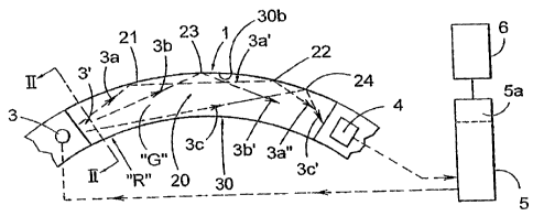
With reference to Figure 2, there is schematically shown the basic
preconditions for the present invention, and where the significant characteris-
tics associated with the invention with respect to the shape of the chamber,
the location of the light-emitting means and the location of the means of re-
ceiving reflected light, are generally made clear through the proposed embo-
diments that will subsequently be described in more detail.
Thus Figure 2 illustrates a gas analysis arrangement 1 with a
construction that is, in principle, equivalent to that shown in Figure 1 and
where equivalent components have therefore been assigned equivalent
reference numerals.
The gas analysis system 1 comprises a chamber 20, containing a
gas sample, a light-emitting means 3, a means 4 of receiving light reflected
through the chamber 20, and an electronic circuit 5, adapted such that it is
able, by means of spectral analysis, to analyse and determine the presence of
and the concentration of a selected gas and/or mixture of gases, present as a
gas sample "G" within the said chamber 20.
The electronic circuit 5 may also comprise a simple comparator, in
order to carry out in the comparator an electronic comparison of the instantan-
3o eous value and a stored limit value such that an optical or an acoustic
circuit is
activated when the determined instantaneous value exceeds the stored limit
value.
CA 02493916 2005-01-17
WO 2004/010116 PCT/SE2003/001235
17
The embodiment according to Figure 2 illustrates for the purposes
of simplification the removal of a section of a wall belonging to the chamber,
facing the reader, in order in this way to be able to illustrate the beam or
ray
path.
The calculating electronic circuit 5 also. comprises, according to
Figure 2, a table 5a, in which a number of selected limit values for a
selected
gas and/or mixture of gases are stored, together with a comparator circuit,
such that an alarm circuit 6, optical or acoustic, is activated in a known man-
ner when the instantaneous value for a selected gas and/or mixture of gases,
1o within the calculating circuit 5, exceeds a limiting value stored in the
table.
Three different embodiments of the selected cross-section of the
chamber 20 are shown in Figures 3, 4 and 5, where Figure 3 illustrates a more
square cross-section next to the light-emitting means 3, Figure 4 illustrates
a
part of an elliptical cross-section, and Figure 5 illustrates a part of a
circular
cross-section.
The following is valid for the embodiment according to Figure 3 -
the surfaces 30a, 30b and 30c, of which surfaces 30a and 30c are directly op-
posite to each other and oriented parallel to each other, offer extremely
highly
light-reflecting properties.
With respect to Figure 4, the partially ellipsoidal surface 40a offers
light-reflecting properties, and with respect to Figure 5, the partially
toroidal
surface 50a offers light-reflecting properties.
Each one of these embodiments comprises at least one aperture
30, 40 and 50, in order in this way to allow a sample "G" of gas to be able ra-
pidly to pass into and out from the said chamber 20, where exchange of gas
will take place via a pronounced diffusion.
The chamber 20 may, as is the case in the embodiment according
to Figure 1, be assigned a long and narrow structure with the said apertures
30, 40 and 50 replacing a part or section of a wall, forming the chamber 20,
where these apertures extend continuously and directly between the said light-
emitting means 3 and the said light-receiving means 4.
CA 02493916 2005-01-17
WO 2004/010116 PCT/SE2003/001235
18
Figures 3, 4 and 5 are to be considered as illustrating the cross-
section of the chamber 20 taken across the section "II-Il" in Figure 2, in the
close vicinity of the light-emitting means 3.
Although Figure 2 shows a side view where the chamber 20 con-
sists of two opposite surfaces 30a, 30c curved to form part of a circular ring
and a partially cylindrical surface 30b, it is clear that curved surfaces
other
than these can be used.
Thus, curves that connect to or are constituted by partial ellipses
can be selected instead of those shaped as a part of a circular ring.
Since the invention is built upon a more or less diffuse image of
the light-transmitting means 3 appearing at the light-receiving means 4, the
possibility of assigning different curvatures and different radii of curvature
to
the curved light-reflecting surface 30b lies within the selected embodiment.
With renewed reference to Figure 2, it is thus illustrated that the
said chamber 20 has been assigned a continuous, somewhat curved, shape,
between the said light-emitting means 3 and the said light-receiving means 4,
here illustrated in the form of a partially circular curvature, the radius of
which
has been given the reference symbol "R".
Not only curvatures that are part of a circular arc, cylindrical cur-
vatures and elliptical curvatures fall within the framework of the invention,
other curvatures that it would be possible to adapt in order for it to be
possible
to allow in the manner proposed by the invention emitted light 3 in the form
of
a divergent light beam or light cone 3' to pass through the chamber 20 to as
great an extent as possible in order to be collected after convergence in the
light-receiving means 4 within its lobe of reception also fall within its
frame-
work.
Figure 2 thus illustrates more exactly, for the purposes of clarifi-
cation, that the light-emitting means 3 can be considered to produce a some-
what diverging (say 15 ) light beam, the central beam or ray 3a of which is
3o directed towards a point 21 and is there reflected to a light ray 3a' that
is di-
rected closer to the horizontal and which in turn is reflected, in a second
point
22, as a light ray 3a" towards and to be received by the means 4.
CA 02493916 2005-01-17
WO 2004/010116 PCT/SE2003/001235
19
The means 3 can be adjusted such that another light ray 3b can
be reflected at a point 23 and transferred as a light ray 3c' to the means 4.
A further light ray 3c from the means 3 is shown reflected at a point 24, in
order to be subsequently reflected to the means 4 as a light ray 3c'.
Directly acting light rays can also, to a restricted amount, be used
in this case.
With reference to Figure 6, it is illustrated that the emitted light be-
am 3', with its light ray 3d, can be allowed to reflect in the parallel and
plane
sections of wall 30c and 30a, and again on the section of wall 30c before the
light ray 3d' is detected by the light-receiving means 4.
The basic idea of the invention is based upon shaped apertures
30, 40, 50, preferably one single aperture, according to Figure 7, although a
number of apertures, where the number is a small number, are to be located
in a single and extended extent between the said light-emitting means 3 and
the said light-receiving means 4 and that the said aperture is to be assigned
a
size and an extent that will have the ability to offer a rapid passive
diffusion for
an exchange of one sample of gas "G" within the chamber 20 for another, and
where it will be possible to adapt as required the rate of the exchange of a
sample of gas within the chamber for another sample.
The free exposure of the chamber 20 that is offered by the inven-
tion by allowing the removal of a section of a wall for the chamber 20
suggests
that it should be possible to reduce the speed and time of diffusion to less
than one second, and preferably also to less than 0.5 seconds.
With reference to Figure 7, it is there illustrated that the aperture
has been divided into two parts 30a and 30b with a section 31 that is located
between them and that covers the chamber, the surface section 31a of which
that faces the chamber 20 may offer highly reflective properties.
The total surface area of the said aperture 30, 40, or 50 and/or
the apertures 30a, 30b is adapted in a co-ordinated manner such that it will
be
possible to cover at least in excess of 15-25% of the total inner surface of
the
chamber 20 between the light-emitting means 3 and the light-receiving means
4.
CA 02493916 2005-01-17
WO 2004/010116 PCT/SE2003/001235
In particular, it is proposed that the total surface area of the aper-
ture 30, 40 or 50, or of 30a, 30b, is to be adapted in a co-ordinated manner
to
cover at least less than 50% of the total inner surface of the chamber, betwe-
en the light-emitting means 3 and the light-receiving means 4, in order in
this
s way to liberate reflecting surface sections and in particular the curved
surface
section 30b.
The total surface area of the said aperture 30, 40 or 50 is, in par-
ticular, adapted in order to cover 20-30% of the total inner surface of the
chamber 20 between the light-emitting means 3 and the light-receiving means
io 4, where Figure 10 suggests a relationship that lies around 25%.
The embodiments according to Figures 3, 4, 5, 6, 7, 10 and 12 al-
low the illustration of the assignment to the said aperture of a square, or es-
sentially square, cross-section, but it should be taken into consideration
that
other forms of the size and shape of the aperture fall within the framework of
15 the invention, anything for the purpose of being able to reduce the
reaction
time for a gas analysis system 1 according to the invention, and in this way
increase the rate of diffusion, preferably by the use of the "active" heat
that is
produced by the light-emitting means 3.
Figure 3 illustrates that the said aperture 30 is assigned one
20 complete side of the four sides of a square.
Figure 4 illustrates that the said aperture 40 is assigned one part
of a curved ellipsoidal surface where this part has been selected to have a
width that is less than one half of the major diameter.
Figure 5 illustrates that the said aperture 50 is assigned one part
of a toroidal or cylindrical surface with a width that is less than the
diameter.
The radius of curvature "R" assigned to the chamber 20 is selec-
ted at a light-emitting means 3 that offers- a large angle of divergence for
the
diverging light beam 3', with central rays having been assigned reference nu-
merals 3a, 3b, 3c and 3d, to be less at a distance "a" of the light-emitting
means from the inner surface 30b of the chamber than it is for a light-
emitting
means 3 offering a small angle of divergence for diverging rays within the
light
beam 3'.
CA 02493916 2010-05-06
21
Said distance is illustrated in Figure 3, and other figures, with the
reference symbol "a".
A filter 60 is adapted to cover the aperture 30 in the embodiment
according to Figure 3, a filter 61 is adapted to cover the aperture 40 in the
em-
bodiment according to Figure 4, and a filter 62 is adapted to cover the apertu-
re 50 in the embodiment according to Figure 5.
Filters of the type used here are well-known and will not be descri-
bed in detail-
In particular, the present invention proposes that the filter surface
io used is to be adapted such that it is able to cover the said aperture 30,
40 or
50 with a factor of 10-25 (1/mm) relative to the volume enclosed by the cham-
ber 20.
The said light-emitting means 3 and the said light-receiving
means 4 are in all embodiments located at the ends of the said chamber 20
is as it has been defined, but there is nothing to prevent allowing the
sections of
surface of the surfaces that form the chamber 20 to extend beyond the defini-
tion of the chamber 20, in order to attach the light-emitting means 3 and the
light-receiving means 4 in the extensions, according to the embodiment shown
in Figure 12-
20 There is nothing to prevent the introduction into the embodiment
according to Figure 12 of a filter 60a instead of the filter 60 in order in
this way
to reduce the .volume of the chamber 20.
Figure 8 is intended to illustrate the beam or ray path from a me-
ans 3 when its light beam 3' is reflected only once in a surface 30b with the
25 shape of an arc of a circle.
As illustrated here, the tight-emitting means 3
is adapted to project a light beam or a light cone 3' onto the concave mirror
surface 30b and where the focussed image of the light-emitting means arises
with high intensity in a means 4 for receiving reflected light.
30 Figure 9 is intended to show a first borderline case, according to
the present invention, where a light-emitting means 3 is adapted to project a
light beam or light cone 3' onto a concave mirror surface 30b and where the
somewhat diffuse image of the light-emitting means 3 arises with a high inten-
CA 02493916 2005-01-17
WO 2004/010116 PCT/SE2003/001235
22
sity in a means 4 for receiving reflected light, and with, in principle, only
two
reflection surfaces or reflection points along the surface 30b.
The focus of the received image may, even in this embodiment,
be too sharp for the image to be used to any advantage according to the prin-
ciples of the invention.
The focus becomes poorer for a higher number of reflections that
are used, and practical experience suggests that the number of reflection
points for the central ray should be selected to be four or approximately
four.
It has been discovered in this case that a central light beam or ray
io 3a, assigned to the light beam 3', (extended in Figure 9 through the mirror
surface 30b) has been adapted to form a small angle "b" with a tangent line 9
of the curved surface 30b next to the means 3.
In particular, it is a question of a central line or ray 3a assigned to
the light beam 3' being adapted to connect to or align with the direction of a
tangent line 9, oriented through a curved concave reflecting surface 30b and
the surface section 30b' that is located next to the light-emitting means 3.
The central line 3a assigned to the light beam is assigned a small
upwards or downwards angle relative to the said tangent line 9, having, how-
ever, a value of angle that is normally within 100 relative to the said
tangent
line.
A strongly focussed light beam or light cone arises in both Figure
9 and Figure 10 in the said means 4 of receiving reflected light without any
direct and focussed image of the light-emitting means 3.
One ray of the light beam 3' or light cone produced by the light-
emitting means, such as its central ray 3a, is adapted to be reflected a few
times in the concave surface 30b before it reaches the light-receiving means
4.
The number of reflections of the central beam or ray is to be sel-
ected in practice to less than eight, such as only two as in Figure 9, while
the
3o number can be selected to between three and five, such as four as in Figure
10.
It is probable that the embodiment according to Figure 10 is to be
preferred for practical application since the number of reflection points for
the
CA 02493916 2005-01-17
WO 2004/010116 PCT/SE2003/001235
23
central beam or ray 3a can be easily controlled by a changing of the angle of
incidence "b" of the central beam or ray 3a onto, and its distance "a" from,
the
curved surface 30b.
Figures 10 and 11 are intended to illustrate a special case, accor-
ding to the present invention, where the light-emitting means 3 is adapted to
project, under a small angle of incidence, the value of the angle "b" being
equal to zero according to the definition given in Figure 9, a light beam or
light
cone 3' onto a concave mirror surface 30b and where the diffuse image of the
light-emitting means 3 arises with a high intensity in a means 4 for receiving
io reflected light and with, in principle, four or five reflection surfaces or
reflection
points for the central light beam or ray.
Figure 11 shows an enlarged drawing of the location of the light-
emitting means next to one end section 30b' in Figure 10 of the reflecting con-
cave surface 30b.
It is shown that the central light beam or ray 3a is parallel to the
tangent line 9, and it is clear from this drawing that the angle "b" can be
chan-
ged to have positive and negative values, where Figure 9 shows a positive
value.
Figure 11 also illustrates that it will be possible to change the dis-
tance "a" with different results for light reception in the means 4.
There is nothing to prevent the application of the same principles
as those described above with respect to the locations and directions of the
light-emitting means and of the light-receiving means with respect to its
light-
receiving lobe.
The practical application of the chamber 20 and the image that is
received by the means 4 thus can be changed by the following factors:
a. the distance "a" selected,
b. the angular value "b" selected,
c. the form and intensity of the light source, and its angle of
3o divergence (approximately 15 ),
d. the position of the means 4 of receiving reflected light and its
angle of reception (approximately 15 ),
CA 02493916 2005-01-17
WO 2004/010116 PCT/SE2003/001235
24
e. the radius "R" of curvature or the curvature selected of the
concave surface 30b for reflecting light,
f. the size and location selected of the aperture 30 for extensive
diffusion of the sample "G" of gas,
g. the location of the chamber 20 such that heat from the light-emit-
ting means 3 will contribute with a convection flow through the chamber 20.
Figure 12 shows a perspective view of an alternative to the embo-
diments according to Figure 2 and Figure 3 with a surface wave-guide system,
where the means 3 and 4 are located at the ends or located between two
io parallel surface sections, separated each by a chord.
A filter 60 interacts with these chords, and the reflecting concave
surface 30b is extended somewhat outside of the relevant measurement dis-
tance in order to interact with and to fix the means 3 and the means 4.
The means 3 can, as is shown in Figure 11, consist of a filament
3g, a light system 3h in order to converge the light beam 3" to a focal point
3""' and from which the diverging light beam or light cone 3a exits.
The filter 60 can be located further into the chamber 20, shown by
the reference numeral 60a, and in this way reduce the volume of the chamber
to the volume that Figure 10 makes clear.
20 Naturally, the invention is not limited to the embodiments specifi-
ed above for the purposes of exemplification. It can be modified within the
framework of the innovative concept illustrated by the attached claims.
Particular attention should be paid to the fact that each unit can
be combined with each other revealed unit within the framework in order to
achieve the desired technical function.