Note: Descriptions are shown in the official language in which they were submitted.
CA 02494145 2005-01-31
WO 2004/012019
PCT/US2003/024029
SYSTEM AND METHOD FOR WIRELESS REMOTE
CONTROL OF LOCOMOTIVES
FIELD OF THE INVENTION
(1] The present invention relates generally to wireless
remote controlled mobile devices and more particularly
to a system and method for the wireless remote control
of locomotives.
BACKGROUND OF THE INVENTION
(2] Current systems and methods used for the wireless/radio
remote control of locomotives, particularly in switching
yards, typically employ a microprocessor based
controller mounted onboard the locomotive and one or
more one-way portable radio transmitters or operator
control units associated with the controller to allow
one or more operators to control the locomotive.
Numerous remote control locomotives are normally used
simultaneously in a given switching yard or remote
control zone.
Current radio remote control systems
employing asynchronous transmission methods can only
handle about 5 to 7 locomotives with associated
transmitters on a single simplex wireless channel or two
half duplex wireless channels (repeater system) when
operating in a given location and with a given command
response time.
Because useable radio frequencies are
limited, this effectively limits the number of remote
control locomotives that can be operated simultaneously
in a given switching yard or remote control zone.
[3] Moreover, remote control systems for locomotives
currently in use also typically employ only one-way data
communication between the onboard controller and the
CA 02494145 2005-01-31
WO 2004/012019
PCT/US2003/024029
operator control units, and therefore can perform only a
limited number of operational and safety functions.
[4] Additionally, current wireless remote control systems
employing more than one repeater in a given switching
yard or remote control zone are often hampered by
interference within sub-zones where repeater coverage
overlaps.
[5] Further, current wireless remote control systems
typically employ components such as radio receivers and
transmitters which are always active and thus more
susceptible to interference from sources outside of the
system.
SUMMARY OF THE INVENTION
[6] Accordingly, the present invention provides a system and
method for remotely controlling an increased number of
locomotives on a single simplex wireless channel or on
two half duplex wireless channels within a given
location. The system employs Time Division Multiplexing
(TDM) or synchronized time sharing protocol to allow
increased numbers of wireless remote control
locomotives, each with a plurality of associated
operator control units (OCUs), to operate on a single
wireless channel or two half duplex wireless channels.
Such protocol comprises dividing a cycle time into a
plurality a time slots and assigning a dedicated time
slot to each subsystem of a locomotive control unit
(LCU) and its associated OCUs in which to communicate
with each other to control the locomotive.
The TDM
protocol may be used in conjunction with one-way or two-
way transmission systems.
-2-
CA 02494145 2005-01-31
WO 2004/012019
PCT/US2003/024029
[7] A synchronization signal, such as a timing signal
broadcast from a GPS satellite or a land-based time
source is used to synchronize timing devices onboard the
LCUs or the OCUs to ensure that the transmissions from a
first LCU/OCU subsystem do not overlap those of a second
LCU/OCU subsystem. The time slots for each subsystem
may be assigned manually, downloaded from a computer,
received from wireless transmissions over a local
wireless network or automatically assigned by the LCU or
OCU after monitoring the wireless channel(s) being used
by the system to find an open time slot to occupy.
[8] When employing one or more repeaters to extend the range
of the system, the LCU or OCU may be set to
automatically select the direct or repeater transmission
path depending upon whether or not responses were
received by the transmitting device to its polling
messages.
[9] Additionally, to minimize interference in sub-zones
where repeater coverage overlaps, each repeater of the
system is assigned a unique address. Each LCU uses GPS
data provided by the associated GPS receiver to
determine the sub-zone of the remote control zone in
which it is located. Based upon such determination, the
LCU determines which repeater to address its polling
message. Repeaters not addressed within a given time
slot mask off to minimize interference and/or the
potential for interference within the system.
Other
system components such as the LCUs and OCUs also
preferably mask off when not expecting to receive a
system transmission to further minimize detrimental
effects from extraneous transmissions and interference.
-3-
CA 02494145 2005-01-31
WO 2004/012019
PCT/US2003/024029
Further, in a preferred embodiment of a LCU/OCU
subsystem of the present invention employing a primary
OCU and a secondary OCU, the secondary OCU may be turned
off and/or later rejoined to the LCU/OCU subsystem in
operation without requiring a stoppage in the operation
of the subsystem.
[10] Positioning data received from a GPS receiver operably
connected to the subsystem is used to determine the
location of the locomotive within predefined zones and
to initiate the execution of predefined functions based
on the location of the locomotive.
[11] Other features and benefits of the present invention
will become apparent from the detailed description with
the accompanying figures contained hereinafter.
BRIEF DESCRIPTION OF THE DRAWINGS
[12] FIG. 1 is a functional block diagram of a preferred
embodiment of the system present invention;
[13] FIG. 2 is a functional block diagram of a preferred
subsystem of the present invention comprising a
Locomotive Control Unit (LCU) and two Operator Control
Units (OCU);
[14] FIG. 3 is a functional block diagram of a preferred
embodiment of the LCU of the present invention;
[15] FIG. 4 is a functional block diagram of a preferred
embodiment of the main computer/decoder board of the LCU
of the present invention;
-4-
CA 02494145 2005-01-31
WO 2004/012019
PCT/US2003/024029
[16] FIG. 5 is a front perspective view of the components of
a preferred embodiment of the system of the present
invention;
[17] FIG. 6 is a front perspective view of a preferred
embodiment of the LCU of the present invention;
[18] FIG. 7 is a front perspective view of the door of the
LCU shown in FIGS. 5 and 6;
[19] FIG. 8 is a functional block diagram of a preferred
embodiment of the transceiver of the LCU of the present
invention;
[20] FIG. 9 is a functional block diagram of a preferred
embodiment of the Global Positioning System (GPS)
receiver of the LCU of the present invention;
[21] FIG. 10 is a front perspective view of a preferred
embodiment of the GPS receiver of the LCU of the present
invention;
[22] FIG. 11 is a front perspective view of a preferred
embodiment of an Operator Control Unit (OCU) of the
present invention;
[23] FIG. 12 is a top perspective view of the OCU shown in
FIG. 11;
[24] FIGS. 13A and 13B are functional block diagrams of a
preferred embodiment of repeaters employed in the system
of the present invention; and
[25] FIG. 14 is a functional block diagram of a railyard or
remote control zone according to the present invention
employing the repeaters of FIGS. 13A and 13B.
-5-
CA 02494145 2005-01-31
WO 2004/012019
PCT/US2003/024029
DETAILED DESCRIPTION OF THE INVENTION
[26] Preferred embodiments of the present invention are
illustrated in the FIGURES, like numerals being used to
refer to like and corresponding parts of the various
drawings.
[27] The synchronous timesharing system of the present
invention maximizes Radio Frequency (RF) spectrum
efficiency by allocating the spectrum to allow an
increased number of remote controlled locomotives (each
to be controlled by a plurality of Operator Control
Units (OCUs)) to operate on a single radio frequency
(simplex channel), or using a pair of radio frequencies
(half duplex channel) when one or more repeaters is/are
required for extended operating range. The system 10 is
based upon operator response time requirements and the
guidelines set forth in the FRA Advisory 2001-01, which
allows for a maximum of 5 seconds of communications loss
before a remote controlled locomotive must be
automatically commanded to stop by the onboard
locomotive control unit.
[28] In a preferred embodiment of the present invention
employing synchronized time sharing or Time Division
Multiplexing (TDM), up to ten (10) controllers or
Locomotive Control Units (LCUs) (each having 2 linked
OCUs) can be individually programmed so that each LCU 12
polls its linked OCUs within its assigned 100
millisecond time slot that is part of a 1-second TDM
cycle. These ten LCUs transmitting on the same simplex
or half duplex frequency channel are individually offset
by 0.1 seconds from the start of a synchronizing time
pulse received by each LCU 12 from an internal Global
Positioning System (GPS) receiver 23 in communication
-6-
CA 02494145 2005-01-31
WO 2004/012019
PCT/US2003/024029
with the GPS satellite constellation.
Timing means
comprising internal clocks or delay timers in each
LCU 12 are synchronized by this time pulse so that they
can be certain to transmit only within their respective
time slots and not interfere with the transmissions of
other LCU/OCU subsystems.
[29] Figure 1 shows in schematic a preferred embodiment of
the system 10 of the present invention comprising a
plurality of subsystems 11 each of which comprises an
LCU 12 onboard the locomotive, a first portable operator
control unit OCU 40, a second portable OCU 44 (as shown
schematically in FIG. 2). A common clock 70 is used to
synchronize the internal clocks in each LCU 12 to allow
for the precise Time Division Multiplexing (TDM) or
synchronized time sharing on the single simplex channel
or dual half duplex channels. As shown schematically in
Figure 2, each LCU 12 preferably comprises a main
computer/decoder board 13, an RF transceiver 14
(alternately, separate receiver and transmitter
components may be used), a power supply 15 and a Global
Positioning System (GPS) receiver 23.
Preferably, the
GPS receiver 23 is mounted on top of the locomotive and
connected to the LCU 12 via cable 34 and serial port 16
(FIGS. 6 and 10). The LCU 12 is operably connected to
the pneumatic interface 7 (FIG. 5) which pneumatically
executes the electronic commands from the LCU 12. The
LCU 12 may also be operably connected to the junction
box 8 (FIG. 5) which interfaces with the wiring of the
locomotive to provide easy access thereto for purposes
related to the system.
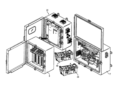
[30] As shown in Figures 5, 6 and 7, the LOU 12 comprises an
outer housing 26 with a hinged door 27 providing access
-7-
CA 02494145 2005-01-31
WO 2004/012019
PCT/US2003/024029
to the interior of the housing 26 which contains a
shielded electronics subchassis 28. The front side 29
of door 27 defines a window 30 through which the display
panel 22 may be viewed.
Pushbuttons 31, 32, the
function of which are described below, are also disposed
on the front side 29 of door 27.
[31] Figure 4 provides a diagrammatic representation of the
main computer/decoder board 13 which further comprises a
real-time clock or a delay logic circuit 17 and
alphanumeric display panel 22 and an I/R link port
comprising an infra-red emitter/ receiver 9 and several
watch dog timers 19, 20 and 21.
Each LCU 12 also
preferably comprises a multiprocessor configuration,
designed specifically to address the safety requirements
of remote-controlled mobile devices such as locomotives.
For example, the radio transceiver 14 of the LCU 12
performs digital signal processing as a 'screening'
technique for all communications traffic. Once
determined to be valid by the transceiver 14, the data
message is forwarded to the first two microcomputers of
the LCU 12 for simultaneous processing.
The data
structure and error checking insures that only the
desired transmitted messages will enter the processing
computer board of the LCU 12.
[32] The computer/decoder 13 of the LCU 12 preferably
comprises three microcomputers each programmed for
various tasks. The control microcomputer processes the
data sent to it from the radio transceiver, checking for
correct address, valid data format, and complete message
with a proper error checking byte appended.
This
control microcomputer performs all digital Input and
Output (I/O) functions to the locomotive valves, relays,
-8-
CA 02494145 2005-01-31
WO 2004/012019
PCT/US2003/024029
sensors etc, and is the primary controlling device of
the LOU 12. The secondary microcomputer is utilized as
a complete 'double check' of all data.
This is
accomplished by processing the entire command message at
the same time the control microcomputer is performing
the same function, after which, both microcomputers
compare the results prior to activating outputs to the
locomotive. The data microcomputer is responsible for
storing any fault information for later retrieval and
viewing, as well as managing a digital voice message via
the locomotive two-way radio system to the operator
control units 40, 44.. This microcomputer also performs
some housekeeping tasks, such as communication with the
GPS receiver 23, controlling the output to the status
display 22, and controlling the IF. 'Teach' / 'Learn'
during the OCU/LCU linking process.
[33] The RF-transceiver 14 of the LOU 12, shown schematically
in Figure 8, comprises an alphanumeric display 24 and a
supervisory timer 25.
[34] The GPS receiver 23, shown in further detail in Figures
9 and 10, comprises a satellite receiver 37, a
microprocessor 38, a clock 39, an antenna 33 and
interface cable 34 to the LOU 12. When powered up, the
GPS receiver 23 self-initializes, acquires satellite
signals from the national GPS satellite constellation,
computes position and time data, and outputs such data
to the LCU 12.
The internal clock 39 of the GPS
receiver 23 is preferably highly accurate and is
synchronized by a signal from one of the very highly
accurate clocks onboard the satellites of the national
GPS satellite constellation.
In addition, the GPS
receiver 23 generates a Pulse Per Second (PPS) output to
-9-
CA 02494145 2005-01-31
WO 2004/012019
PCT/US2003/024029
the LCU 12 synchronized to Coordinated Universal Time
(UTC) within 50 nanoseconds (1 sigma).
The AcutimeTM
2002 GPS Smart Antenna and Synchronization Kit available
from Trimble Navigation Limited, Sunnyvale, CA, is a
commercially available GPS receiver of the type
disclosed herein.
[35] As an alternative to GPS receiver 23, the means for
receiving a synchronization signal of the LCU 12 could
comprise a receiver (not shown) for receiving the time
signals broadcast by the Time and Frequency Division of
the National Institute of Standards and Technology over
the WWV, WWVB or WWVH radio stations for the purpose of
synchronizing a clock, timer or delay logic circuit of
each LCU 12.
Further, a private radio broadcasting
station could be constructed within the railyard or a
remote control zone to broadcast time signals generated
by a clock of very high accuracy, such as an atomic
clock for example, to be received by a dedicated
receiver in each LCU 12. In addition, time signals can
alternatively be transmitted to each LCU 12 within a
given location by other means such as infra-red or other
light transmissions, or a wireless computer network in
which case each LCU 12 would also comprise a wireless
network card (not shown).
In summary, each LCU 12
preferably comprises means for synchronizing the LCU 12
with an external timing source for the purpose of Time
Division Multiplexing (TDM).
The means for
synchronizing would preferably comprise a means for
receiving a synchronization signal from the external
timing source and a timing means such as a clock or a
delay logic circuit.
The means of the LCU 12 for
receiving the synchronization signal preferably comprise
-10-
CA 02494145 2005-01-31
WO 2004/012019
PCT/US2003/024029
a GPS receiver, an infrared receiver, a radio receiver
or a wireless network card.
[36] Individual rail yards or remote control zones are
allocated specific radio frequency channels that are
normally duplicated at other rail yards and remote
control zones. Remote control locomotives with onboard
LCUs operating within an individual rail yard or remote
control zone are programmed with matching radio
frequency channels.
[37] Each LOU 12 operating within an individual rail yard or
remote control zone is allocated a specific time slot in
which to transmit polling messages to its associated
OCUs. Initially, this time slot is factory programmed
for a particular rail yard or remote control zone so
that the LCU 12 fits into the wireless 'time-sharing'
sequence plan or TDM plan for that location.
The
programmed frequency and address of each LCU is
transferred to one of many associated Operator Control
Units (OCUs) during a teach/learn process (described
below) by way of an Infra-Red (IR) link.
[38] Consequently, if an LCU 12 is moved out of its
designated rail yard or remote control zone, its
frequency channel and time slot allocation must be
reprogrammed to fit in with its new rail yard or remote
control zone.
[39] It is recommended that up-to-date records be kept of
individual frequency and time slot allocations for each
LCU 12 at individual rail yards and/or remote control
zones, including any new frequency and time slot
allocations made in the field by maintenance or
operating personnel. Such records will help to ensure
-11-
CA 02494145 2005-01-31
WO 2004/012019
PCT/US2003/024029
that no two LCUs have been assigned the same time slot.
Duplicating time slots may result in unexpected
communications losses that may cause the affected LCUs
to shut down.
[40] In the preferred embodiment of the present invention,
various programming options may be used to program the
frequency and time slot allocations for each LCD 12.
[41] In a user select option, yard employees can select from
pre-programmed frequency channels stored in the LCUs
memory and similarly select the time slot for the LCD to
occupy in the wireless 'time-sharing' sequence or TDM
plan. The channels and time slot are changed using the
existing function pushbuttons 31, 32 located on the
front side 29 of LCU door 27 while observing prompts on
the alphanumeric display 22 as viewed through the front
door window 30 of the LCD 12 (FIGS. 6 and 7).
[42] In the manual procedure for field selection of an RF
channel, the operator presses and holds the 'YES/ALARM
RESET' button 32 for longer than 2 seconds, releases the
button' for longer than 2 seconds, and repeats this cycle
a total of three times.
The display 36 will then
indicate 'SELECT RF CHANNEL 1L'.
The 'NO/FUNCTION'
button 31 is then used to increment from 1 through 30
channel numbers. When the desired channel number (e.g.,
1H) has been selected, the 'YES/ALARM RESET' button 32
is pressed to lock the LCD 12 on the channel number
displayed. Once a channel is selected, the status
display 22 changes to indicate "SELECT TIME SLOT 1".
Again, the 'NO/FUNCTION' button 31 is used to increment
between time slots 1 through 10. When the desired time
slot has been selected, the 'YES/ALARM RESET' button 32
is pressed to lock the LCD 12 on that time slot. The
-12-
CA 02494145 2005-01-31
WO 2004/012019
PCT/US2003/024029
LCU 12 display 22 will show the channel and time slot
selections and ask if they are correct.
Here, the
'YES/ALARM RESET' button 32 is pressed to complete the
selections or the 'NO/FUNCTION' button 31 is pressed to
start over.
[43] The LCU channel and time slot selections may also be
downloaded to the LCU 12 from a portable computer via
known linking/transfer means including an infrared port,
a wired or wireless network or a serial cable connected
to a communications (COM) port located on the underside
of the shielded electronics sub-chassis 28 of the LCU
12.
The download is performed by first opening the
front door 27 and turning OFF the power to the LCU 12
using a power switch (not shown). The portable computer
is then connected to the COM port (not shown) on the
sub-chassis 28 using a serial cable with a DB-9
connector (this may require disconnecting an optional
event recorder).
Instead of connecting a portable
computer to the COM port, an interface cable may be
provided to allow the computer to interface directly to
the external connector 5 on the enclosure 26.
Once
connected to the LCU 12, the desired table of
frequencies and parameters are downloaded into the
battery backed memory of the LCU 12. The LCU 12 is then
turned on and the upload button (not shown) is selected
to complete the transfer of information.
The newly
programmed information can then be read and verified on
the LCU display 22. The serial cable is disconnected
and the door 27 is closed and secured to complete the
process.
[44] Additionally, pre-programmed radio or other wireless
communications channel frequencies stored in memory in
-13-
CA 02494145 2015-07-10
the LCU 12 may be selected automatically by the LCU 12
based upon position data from the GPS receiver 23.
Known radio frequencies used at various geographic
locations can be stored in the LCU's memory and
automatically selected when, via GPS, the locomotive
determines that it has entered a location or zone
requiring a different channel selection. Other position
determining means may consist of inertial guidance
systems and other ra,lio navigation technology such as
Loran, local pre-surveyed position transmitters, and
local area networks.
[45] In a similar
manner, the onboard LCU 12 can use the
position data provided by the GPS receiver 23 to
establish yard limits to prevent a locomotive from
operating outside of a defined geographic location.
Using GPS, the LCU 12 could be programmed to command a
full service shutdown and emergency brake application if
the locomotive traveled outside of the defined yard.
GPS data from the GPS receiver 23 can also be employed
to detect false standstill signals provided to the LCU
12 by an onboard velocity/direction sensor, such as an
axle pulse generator of the type well known in the art
as disclosed in U.S. Patent No. 5,511,749, which has
failed. Here, the LCU 12 would compare sequential
signals from the GPS receiver 23 to determine if the
locomotive is moving and the direction of movement. If
this data contradicts data received from the
velocity/direction sensor, the LCU 12 would command a
full service shutdown and emergency brake application.
-14-
CA 02494145 2005-01-31
WO 2004/012019
PCT/US2003/024029
Electronic Position Detection (EPD)
[46] In a preferred embodiment of the Electronic Position
Detection (EPD) system of the present invention, the LOU
12 is programmed to automatically slow and/or stop the
controlled locomotive within pre-defined zones, or at
specific locations on the track. Additionally, the LCU
12 can be programmed using positional information from
the GPS receiver 23 to override excessive speed commands
from the OCUs 40, 44 within specified areas.
[47] There are two (2) independent EPD systems that may be
programmed into the LOU 12, EPD-GPS & EPD - TAG. Each
can be programmed to work as a primary or back up system
to the other.
[48] (i) TAG READER SYSTEM (EPD-TAG): The first (primary if
used) position detection system is a transponder system.
The system consists of a radio frequency (RF)
interrogator reader and attached antenna system which
are mounted on the locomotive, providing input data via
communications software within the LCU 12.
For speed
limiting applications, a comprehensive track profile
study is completed prior to programming.
The
engineering and programming is based on parameters such
as track grade, curves, maximum train tonnage and
weakest motive power used to pull the train.
Once
design is complete, passive transponders are placed in
the track at positions where the required action is to
be taken.
As the locomotive passes over the
transponders, the EPD-TAG system will sense the
transponder and pass data via radio to the transceiver
14 of the LCU 12, which will in turn carry out the pre-
defined operation.
-15-
CA 02494145 2005-01-31
WO 2004/012019
PCT/US2003/024029
[49] Each tag is pre-programmed with a 10 digit ID
representing the action to be taken. The format of
information contained in the tag is as follows:
[50] Digits 1-2: Speed limit of locomotive until next
transponder is read. Speed can be programmed from 0-
15MPH in 1MPH increments (D1 represents the ten digit
and D2 represents the one digit - i.e. 10 would have
D1=1 and D2=0, 9 would have D1=0 and D2=9, etc.). For
tags being used to identify a track that is not subject
to pullback protection, the tag will be programmed with
99 for D1 and D2.
[51] Digits 3-4:
Used as a check to ensure proper
interpretation of the read tag.
These two digits are
calculated by taking the absolute value of 90-D1D2.
[52] Digits 5-10: Programmed with a 0 in each position
(unused).
[53] Programming chart for tags:
D1 02 D3 D4 D5 D6 D7 D8 D9 D10
MPH 1 0 8 0 0 0 0 0 0 0
9 MPH 0 9 8 1 0 0 0 0 0 0
8 MPH 0 8 8 2 0 0 0 0 0 0
7 MPH 0 7 8 3 0 0 0 0 0 0
6 MPH 0 6 8 4 0 0 0 0 0 0
5 MPH 0 5 8 5 0 0 0 0 0 0
4 MPH 0 4 8 6 0 0 0 0 0 0
3 MPH 0 3 8 7 0 0 0 0 0 0
2 MPH 0 2 8 8 0 0 0 0 0 0
1 MPH 0 1 8 9 0 0 0 0 0 0
0 MPH 0 0 9 0 0 0 0 0 0 0
No Pullback 9 9 0 9 0 0 0 0 0 0
-16-
CA 02494145 2005-01-31
WO 2004/012019
PCT/US2003/024029
[54] Some features of the transponder system are:
[55] (a) The transponder system does not require an FCC
license.
[56] (b) The unit will work through snow, ice, concrete,
wood, rocks and other non-metallic materials that may be
present in a typical yard environment.
[57] (c) The system is limited to a maximum operating speed
of 30 MPH.
[58] The above programming allows the tags used throughout
the railroad to be kept "generic". A track profile will
be created and stored in the LCU 12 specifying the
distance to next tag and distance to end of pullback
authority. When a locomotive is moved between yards,
the track profile for the new yard will need to be
entered into its LCU 12. The LCU 12 will continuously
search for transponders.
[59] (ii) GPS BASED ZONE IDENTIFICATION SYSTEM (EPD-GPS):
This equipment and software may be the primary stand
alone system, or a secondary system used to back-up the
primary tag reader system.
The LCU 12 utilizes the
positional information from the GPS receiver 23, with
software additions to the LCU 12 for implementation.
[60] Two position points, identified by latitude/longitude
coordinates for each point, are entered into the LCU 12
to define the opposite corners of the boundary for each
predefined zone. The size and shape of the zone is then
determined.
These zones may be as small as the
tolerance of the GPS receiver accuracy, (typically 50
feet in diameter or three feet in diameter using
-17-
CA 02494145 2005-01-31
WO 2004/012019
PCT/US2003/024029
differential GPS) to as large as an entire yard
location.
Once identified, the boundaries form a
rectangle that can be overlaid on to a yard map,
creating a specific zone number. Zones can be overlaid
for multiple functions or limits in the same area. For
example, a large zone may have a limit of 4 MPH, with an
underlying zone having a stop area defined within the
larger zone.
[61] The functional purpose of the zone will determine the
number of zones required. Additionally, the placement
and size of the zones requires a study to be performed,
determining the areas of operation, the critical areas
for these operations and a risk analysis by the railroad
to determine if additional safety devices are required
in specific locations (i.e. derailers, etc.). The zones
will have a tolerance based upon the GPS error at the
proposed location, the timing within the LOU and the
error within the GPS system itself.
This can be
accounted for in the design of the zone application.
Once the zones are established, additional programming
is downloaded to the LCU to interact with the OCUs to
perform the functions necessary, as well as inform the
OCU operator with any text status pertinent message.
[62] Locomotive operation between zones can be detected and
used in programming functionality within the LOU 12
(e.g. limit speed in one direction, but not the other).
Track profiles and zones can be loaded into the LOU 12
using a laptop PC, via a serial connection or wireless
LAN.
[63] Additionally, there will be an override function that
can be enabled from the LCU 12. This will allow the
operator to bypass the EPD system and continue the move
-18-
CA 02494145 2005-01-31
WO 2004/012019
PCT/US2003/024029
out of the protected limits.
This override must be
initiated on the locomotive to ensure that the operator
is "at the point" prior to commanding the movement
without protection.
[64]
Figures 11 and 12 illustrate a preferred OCU of the
present invention. As both OCUs 40, 44 are identical,
the following description is equally applicable to both
and like reference numerals have been used to refer to
the components of each OCU 40, 44.
Each OCU 40, 44
comprises a pair of harness mounting clips 45 for
attaching a harness worn by the operator to carry the
OCU. An on/off button 61 is used to turn on or shut off
the device. Various LED indicator lights on the OCUs
include speed indicators 46, headlight brightness
indicator 47, forward, neutral and reverse direction
indicators 48, transmit and low battery indicators 50,
automatic brake position indicators 52 and independent
brake position indicators 53. Text and status display
49 shows text and status messages received from the LCU
12 and from the other OCUs (in a two OCU set-up). A
transceiver (not shown) and antenna 51 of each OCU 40,
44 transmit signals from the OCUs and is used to receive
signals from the LOU 12, repeater 80 (when part of the
system) and the other OCU (in a two OCU set-up). Each
OCU 40, 44 may also preferably comprise means for
synchronizing the OCU with an external timing source for
the purpose of Time Division Multiplexing (TDM). Here,
the means for synchronizing would preferably comprise a
means for receiving a synchronization signal from the
external timing source and a timing means such as a
clock or a delay logic circuit. The means of the OCU
for receiving the synchronization signal preferably
-19-
CA 02494145 2005-01-31
WO 2004/012019
PCT/US2003/024029
comprise a GPS receiver, an infrared receiver, a radio
receiver or a wireless network card.
[65] The independent brake selector lever 54 and automatic
brake selector 56 allow the operator to override the
automatic speed control of the LCU 12 and command
settings of the independent and automatic brakes,
respectively.
The speed selector lever 66 allows the
operator of the OCU to command various speeds of the
locomotive.
[66] While the speed setpoints are fully programmable to suit
any application, they are generally set with the
following settings. The "STOP" setting when commanded
brings the locomotive to a controlled stop by returning
the throttle to idle and commanding a full service
reduction of the brake pipe and a full application of
the independent brakes. The "COAST B" setting returns
throttle of the locomotive to idle and applies 15 pounds
of independent brake pressure, allowing the locomotive
to gradually come to a stop.
The "COAST" setting
returns the throttle of the locomotive to idle and
allows the locomotive to coast without brake
application. In both the "COAST B" and "COAST" settings,
if the speed of the locomotive increases above a pre-
determined set point (e.g. 7 mph) independent braking
will be applied until the locomotive slows below the set
point.
In the "COUPLE" speed setting, the LCU 12
automatically adjusts the throttle and brake settings to
maintain a speed of one mph + 0.1 mph. Likewise in the
speed settings for 4 mph, 7 mph, 10 mph, and 15 mph, the
LCU automatically adjusts the throttle and brake
settings to maintain those respective speeds + 0.5 mph.
To prevent accidental speed selection commands from
-20-
CA 02494145 2005-01-31
WO 2004/012019
PCT/US2003/024029
lever 66 when moving from the STOP position to a
different speed setting, the operator must first
activate either vigilance pushbutton 55, 64, then select
the desired speed within 5 seconds.
If the operator
fails to select the speed within the 5 second window, he
will be required to activate either vigilance pushbutton
55, 64 again before making the speed selection.
[67] The three-position toggle switch 63 allows the operator
to command the following direction of travel: forward,
neutral and reverse. If direction is changed while the
locomotive is moving, a full service reduction will be
automatically commanded by the LOU 12. Additionally,
any time a direction of travel opposite to the commanded
direction of travel, as determined by the
velocity/direction sensor or the LOU 12 with input from
the GPS receiver 23, persists for longer than 20 seconds
while the OCU is commanding movement, a full service
reduction will also be automatically commanded by the
LOU 12.
[68] The two multiple function pushbuttons 55, 64 are used to
reset vigilance timers, acknowledge warning signals sent
by the LOU 12 and accept a "pitch" of control authority
from the primary OCU. When the OCU is the primary OCU
40, the pitch pushbutton 62 may be used to transfer
control authority to the secondary OCU 44.
The
secondary operator must accept such transfer by pushing
either of the buttons 55, 64 to complete the transfer of
control authority. Additionally, the pushbuttons 55, 64
when held for longer than 2 seconds, will command that
sand be dispensed in the direction of travel for as long
as the pushbuttons are depressed.
The operator is
required to activate a control function at least once
-21-
CA 02494145 2005-01-31
WO 2004/012019
PCT/US2003/024029
every 60 seconds. If the operator fails to change the
state of any of the control functions for 50 seconds,
the OCU will begin to emit a pulsed audible warning from
the sonalert (beeper) 65. Either prior to, or during
the audible warning, the operator is required to reset
the vigilance system timer by activating either of the
vigilance pushbuttons 55, 64. If the operator fails to
reset the vigilance system, a full service reduction
shutdown of the automatic brakes will be automatically
commanded by the LCU 12. The vigilance system is only
active and required on the primary OCU 40 and only when
a speed other than STOP is selected by the operator.
[69] The bell/horn toggle switch 58 has one momentary and two
maintained positions. When the switch 58 is held in the
momentary position, the OCU commands the LCU 12 to ring
the bell of the locomotive and sound the horn for as
long as the operator maintains the switch in this
momentary position. When moved to the center position,
the switch 58 turns on the locomotive's bell and when
moved to the third position, turns off both the bell and
the horn.
[70] An internal tilt switch senses when either the OCU 40,
44 is tilted more than 45 + 15 past upright and sends a
shutdown command to the LCU 12, which, in turn, commands
an emergency brake application, returns the throttle to
idle and activates a remote man-down synthesized voice
transmitter. When the OCU is tilted beyond limits for
one second, the OCU will begin emitting an audible
warning from beeper 65 alerting the operator that he is
about to enter into a tilt shutdown. If the operator
does not return the OCU 40, 44 to an upright position
within 5 seconds from the time the warning sounds, the
-22-
CA 02494145 2005-01-31
WO 2004/012019
PCT/US2003/024029
shutdown command will automatically be sent to the LCU
12. Using the time/status toggle switch 60, the tilt
shutdown feature can be delayed for a preset time (e.g.
15 seconds) when the switch 60 is moved to the time
position (the locomotive must also be at a complete stop
for such time extension).
Additional time cannot be
added by repeatedly commanding or maintaining the time
feature. If the operator has not returned the OCU to an
upright position before the preset time expires, the LCU
12 will automatically command an emergency shutdown.
When the switch 60 is moved to the status position, the
output on display 49 will be updated with any relevant
text message.
[71] Typically, the independent brake override lever 54 is
configured with the following selections.
When the
"REL" position is commanded, the independent brakes are
released and placed under the control of the LOU 12 for
maintaining the speed selected by lever 66. When the
lever 54 is set to "LOW", "MED" and "HIGH", 15 pounds,
30 pounds and 45 pounds of independent brake pressure
are applied respectively. When the lever 54 is set to
the "EMERG" position, the throttle is set to idle and an
emergency application of the automatic braking system is
commanded by venting the brake pipe to atmosphere, thus
commanding a full reduction of the train brakes as well
as an emergency application of the independent brakes.
[72] The automatic brake override toggle switch 56 is a three
position switch with the following positions: forward
is a momentary setting which allows toggling of the
selection towards the "CHARGE" setting as shown in
Figures 11 and 12. The hold position (center) holds the
current selection and the reverse toggles the selection
-23-
CA 02494145 2005-01-31
WO 2004/012019
PCT/US2003/024029
towards the "REL" or release setting. The following
settings can be selected: the "REL" setting commands a
release of the automatic brakes and places them under
the control of the LCU 12 for maintaining the speed
selected by lever 66. Three conditions are required for
an automatic brake release: (1) the main reservoir air
pressure must be greater than a preset point (e.g. 100
psi), (2) a suitable brake pipe leakage test must have
been passed and (3) at least 90 seconds has elapsed
since a previous release was commanded.
The "MIN",
"LIGHT", "MED", and "FULL" positions command 7 lb., 12
lb., 18 lb., and 27 lb. reductions of the brake pipe
pressure, respectively. The "CHARGE" setting commands a
release of the automatic brakes until a sufficient
charge is detected on the brake pipe and movement of the
locomotive is disabled until a full charge is detected.
[73] The OCUs 40, 44 will have two free running firmware
clocks set to provide the following:
[74] The first clock is approximately 250 ms and performs a
switch read at "wake-up". The second clock will "wake
up" the OCU processor at approximately 950 ms after
receipt of the last polling message/ synchronization.
[75] The first clock gives the signal for the OCU to read and
store in memory momentary switch positions every 250ms.
The second clock signals the OCU to read all other
switches at the 950 ms time period and to:
[76] (i) build the switch position message to be transmitted
to the OCU 12;
-24-
CA 02494145 2005-01-31
WO 2004/012019
PCT/US2003/024029
[77] (ii) change the state of LEDs on the OCU to the status
reported by the previous polling message from the LCU
12;
[78] (iii) activate the RF receiver of the OCU to receive
the next polling message from the LCU 12; and
[79] (iv) hold the data to be transmitted in a "ready to
transmit state" until the second clock expires at
1000.01 ms from the last synchronization or transmit
data upon receipt of the new polling message from the
LOU 12 which generates a new synchronization pulse right
after the message is successfully decoded by the OCU,
whichever occurs first.
Normally, the new
synchronization at 1000 ms from the time of the prior
polling message will occur first.
[80] The OCUs 40, 44 will have two RF message structures that
are responses to polling messages from the LOU 12:
[81] (i) The RF initialization messages (one from each OCU
40, 44) - primary OCU 40 response is approximately 36 ms
and secondary OCU 44 response is approximately 27.4 ms.
[82] (ii) The RF operational messages (one from each OCU) -
primaRy OCU 40 response is approximately 36.1 ms and
secondary OCU 44 response is approximately 23.1 ms.
[83] In addition, an allowance comprising an additional few
milliseconds of time in the overall process to allow for
a free running (non-synchronized) clock state in the
LCUs and/or OCUs.
[84] Since the system preferably updates messages once per
second, it is possible for the operator to press and
release momentary functions on the OCUs in less time
-25-
CA 02494145 2005-01-31
WO 2004/012019
PCT/US2003/024029
than the one second message update. For this reason, it
is necessary to evaluate each momentary function in
order to accommodate this type of operation. Momentary
OCU functions are: Vigilance Reset, Accept Pitch, Sand,
Horn/Bell, Status Request, Time Extend, and Headlight.
[85] Generally, the situation and performance requirements
for the OCUs 40, 44 will be satisfied in one of three
ways:
[86] (1) Constantly sample each switch of each OCU 40, 44 at
250 ms intervals.
This will be the minimum switch
activation time (average of 125 ms).
This results in
any switch operation being "de-bounced" and therefore
requires the operator to hold the intended switch
function for at least this length of time.
Switch
sampling will be processed by either the display CPU or
the M840 CPU of each OCU 40, 44.
[87] (2) A bit will be included as part of each poll request
from the LCU 12. This bit will "inform" the OCU's 40, 44
that the LCU 12 has successfully received a valid
message from each operating OCU 40 and 44 within the
previous one second. This bit will be used as a
"cancellation bit" and normally will be a zero (0) but
set to a one(1) as the result of recognizing two "good
messages," one from each of the OCU's 40, 44 (only one
good response required if in single operator mode). The
cancellation bit will be sent in every poll message.
[88] (3) VIGILANCE Reset, ACCEPT and SAND functions are all
part of the same switch on the OCUs 40, 44. There are
two of these switches 55 and 64, one on the left front
corner of each OCU 40, 44 and the other on the right
front corner of each OCU 40, 44. The OCU program will
-26-
CA 02494145 2005-01-31
WO 2004/012019
PCT/US2003/024029
read both of these switches 55 and 64, and perform as
follows:
[89] If pressed and held for >250 ms but < two seconds, the
VIGILANCE (ACCEPT) will be sent from the OCU for 5
seconds, or until canceled by receiving the
"cancellation" bit prior to the 5 second expiration.
Notice, that the VIGILANCE bit is used to perform the
ACCEPT function at the decoder end of the system. There
is no need for a unique bit.
[90] If pressed and held for > two (2) seconds the SAND bit
will be sent for 5 seconds or until canceled by
receiving the "cancellation" bit prior to the 5 second
expiration.
[91] For the HEADLIGHT, STATUS AND TIME switches, when
pressed and held for >250 ms, their respective function
bits will be sent from the OCU for 5 seconds, or until
canceled by receiving the "cancellation" bit prior to
the 5 second expiration.
[92] The HORN/BELL switch 58 will have two bits associated
with its activation. If the switch is detected as being
= pressed and released for < one (1) second, it will send
the "short horn" bit. This bit will be programmed at
the LOU 12 to provide a "one shot" timer to the horn of
approximately 11 second. If the switch 58 is detected as
being pressed for > 1 second, it will send the "long
horn" bit which will be transmitted for 5 seconds, or
until the cancellation bit is received at the OCU.
-27-
CA 02494145 2005-01-31
WO 2004/012019
PCT/US2003/024029
Initialization of the System Prior to Radio
Communications
[93] In a preferred embodiment of the system 10 of the
present invention, a unique digital permanent address is
embedded within each LCU 12. Each OCU 40, 44 also has a
unique digital permanent address embedded at the time
of manufacture. The permanent 16-bit address
identification used in the present invention prevents
accidental duplication by maintenance personnel, and
when combined with the LCU address of 16 bits, results
in a potent system identifier.
[94] In order for the LCU 12 and the OCUs 40, 44 to operate
as a system, they must first exchange their digital
addresses to associate the OCUs 40, 44 with the LCU 12.
In this manner, the LCU 12 will recognize and accept
signals from only the OCUs 40, 44 and not from any
others. The operation of the system 10 begins when two
operators, each carrying one of the OCUs 40, 44 with a
fully charged battery, board the locomotive.
Once
onboard the locomotive, the operators will start the
engine in the normal manual fashion. All safety
procedures and operational characteristics of the
locomotive are confirmed to be working properly. The
locomotive is then transferred to "Remote" mode using
designated selector switches and valves.
[95] Next, the operators approach the window 30 of the
onboard LCU 12 and one at a time, with the "primary"
operator first entering a teach/learn mode using the
designated pushbuttons sequence on his portable OCU 40.
A menu on the display screen 49 of each OCU 40, 44
prompts the operators through the sequence necessary to
transfer information from the LOU 12 into each of the
-28-
CA 02494145 2005-01-31
WO 2004/012019
PCT/US2003/024029
OCUs 40, 44 and vice versa. The infra-red teach/learn
process of the present invention between the LCU 12 and
the OCUs 40, 44 provides operational security without
the need to change plugs, keys or any other devices to
link the OCUs 40, 44 with the LCU 12 for an operating
session.
[96] The typical scenario is where a first operator
approaching the display screen 30 of the LCU 12,
starting the process on his OCU 40, and following the
display sequence. The OCU 40 will automatically begin
Infra-Red (IR) communications with the
IR
emitter/receiver 9 of the LCU 12, make audible sounds
while the data exchange is in progress, and finally, the
display 49 will show when the programming is complete.
Some of the data transferred is the address from each
OCU 40, 44 into the LCU 12 and the transfer of the LCU
12 address to the OCU 40, 44.
When the teach/learn
process is completed, the two OCUs 40, 44 will have all
necessary information to safely and accurately operate
as a system with the LCU 12.
[97] Part of the IR teach/learn process is to identify the
primary OCU 40 and the secondary OCU 44. By identifying
and programming one of the OCUs as secondary, limits are
placed on the amount of data that can be transmitted by
that OCU and, therefore, limits its scope of operation.
In other words, the data message transmitted by the
secondary OCU 44 is unique from the data message of the
primary OCU 40. The data message of the secondary OCU
44 is shorter in length and does not have the command
authority of the primary OCU 40.
-29-
CA 02494145 2005-01-31
WO 2004/012019
PCT/US2003/024029
[98] In some cases the secondary operator may not be
utilized, in which case, this step is skipped for the
secondary OCU 44 resulting in primary only operation.
Initializing of the RF Communications
[99] Once the IR teach/learn cycle has been completed, the
radio remote control operation of the locomotive with
LCU 12 on-board can begin. In the state where both OCUs
40, 44 are turned off, the onboard LCU 12 is in an
"offline" polling mode. The LCU 12 transmits a signal,
approximately once every second, in an attempt to
establish a communications link with each of the
portable OCUs 40, 44. This is commonly referred to as a
"polling request" or "polling message".
[100] The LCU 12 will not respond to any acknowledged messages
from any OCUs other than those to which it was
associated with in the IR teach/learn process.
[101] If either the primary OCU 40 or secondary OCU 44 is
turned on within radio range of the LCU 12, it will
receive the polling request from the LCU 12. Each OCU
40, 44 will acknowledge the polling request within the
predetermined time period assigned to each OCU during
the IR teach/learn process. Such time period is known
as a "time slice".
[102] The time slices are assigned during the IR teach/learn
process, whereby the OCU 40, if assigned the first time
slice will always respond in the first time slice
immediately following the polling message regardless of
its status as either primary or secondary.
In this
case, the second time slice is always assigned to the
OCU 44 (when two OCUs are used). Once both OCUs 40, 44
-30-
CA 02494145 2005-01-31
WO 2004/012019
PCT/US2003/024029
are turned on, the primary OCU 40 is capable of running
all the functions onboard the locomotive, while the
functionality of the secondary OCU 44 was limited
internally when it was designated as the secondary OCU
during the IR teach/learn process. After both OCUs 40,
44 acknowledge the polling message, the locomotive is
ready for operation by the primary OCU 40.
[103] For safety reasons, when both the primary and secondary
OCUs 40, 44 have been initialized in the teach/learn
process, they both must receive the polling messages
from the LOU 12 and provide valid responses within five
seconds in order for the system to continue operation in
this mode.
[104] The LOU 12 preferably incorporates two timers 19 and 20
which monitor the primary and secondary OCUs 40, 44,
respectively. The timers 19, 20 may embody hardware or
software timers and monitor when the last valid response
to a polling message of the LOU 12 was received from
each of the OCUs 40, 44, respectively.
If a valid
response has not been received from the primary OCU 40
and the secondary OCU 44 (in a two OCU setup) within the
previous five seconds, the respective timer(s) 19, 20
will cause the LOU 12 to effect a full service shut down
and emergency braking application in the locomotive. As
described below in the Section on Dismissal and Re-
joining of Secondary OCU, the present system
incorporates means for activating or de-activating the
timer 20 so that the secondary OCU 44 may be turned off
for a period of time and then turned back on without
shutting down the locomotive.
In its next polling
message, the LOU will also send a signal to each OCU 40,
44 which activates the beeper 65 sounding an audible
-31-
CA 02494145 2005-01-31
WO 2004/012019
PCT/US2003/024029
alarm to warn the OCU operators of the impending
locomotive shutdown.
Such warning could also be a
visual alarm such as a flashing light and is
particularly for operators who may be riding on the
locomotive or the cars it is moving to provide advance
notice of the impending braking application so that they
can hold on and avoid being thrown from the train.
[105]
In addition, each OCU 40, 44 also includes its own
internal hardware or software timer which is reset by
the "high" position of the reset bit included in each
polling message from the LCU 12.
This status bit
attains the "1" or high state only after at least one
valid response transmission has been received by the LCU
12 within the prior five seconds from each of the
primary and secondary OCUs 40, 44 (in a two OCU setup).
Thus, in a situation where the primary OCU 40 has
transmitted valid responses to each of the last five
polling messages of the LCU 12 and such responses were
received by the LCU 12, the internal timer of the
primary OCU 40 would not be reset where the LCU 12 had
not also received at least one valid response to one of
its polling messages during that same five second
period. In this case, the timer 20 of the LCU 12 which
monitors the secondary OCU 44 would time out and trigger
the LCU 12 to initiate a full service shutdown and
emergency braking application in the locomotive.
At
about the same time, the internal alarm timers in each
of the OCUs 40, 44 would also time out since the reset
status bit in each of the last four polling messages of
the LCU 12 was not in the high state, since the
secondary OCU 44 had not provided a valid response to
any of the last five polling messages transmitted by the
LCU 12. In this situation, the internal timers in each
-32-
CA 02494145 2005-01-31
WO 2004/012019
PCT/US2003/024029
of the control units 40, 44 would initiate an alarm,
such as an audible sounding of beeper 65 or a visual
alarm, to warn the operators of the impending system
shutdown.
[106] The FRA safety advisory requires that the locomotive be
brought to a 'STOP' if there is communications loss
greater than 5 seconds.
The present system satisfies
this minimum requirement to solve a serious potential
operational problem of remote control locomotives that
occurs upon loss of communications, should this occur.
The LCU 12 is programmed so that after 2.5 seconds of a
communications loss, a light brake application is
initiated simultaneously with elimination of tractive
effort.
This allows for some slack action stability.
If communications are re-established between 2.5 seconds
and 5 seconds, the LCU 12 resumes normal operation of
the locomotive.
[107] If the communication loss continues to full term of 5
seconds, the OCU alarm timers trigger an alarm and the
LCU 12 sends the OCUs a timely audible warning that an
unsolicited 'Full Service Brake Application' is about to
occur. This allows operators to 'be prepared' if they
are riding the side of a car. After the full term of
the FRA mandated communication loss is reached and a
stop is initiated, a special operator sequence is
required to recover the system.
[108] Conditions that may occur in operation of the system 10
and the corresponding messages displayed on display
screen 49 of the OCUs may comprise:
[109] (i) Communications lost to the secondary OCU 44:
-33-
CA 02494145 2005-01-31
WO 2004/012019
PCT/US2003/024029
[110] OCU B will show: OCU COMM LOSS and sound the alerter
tone for about 2 seconds.
[111] (The green transmit LED 50 will have stopped responding
seconds prior)
[112] Simultaneously the primary OCU 40 will show "POLL -
OFFLINE" - indicating this OCU 40 is receiving and
responding to a POLL but the LOU 12 is "OFF LINE" - in
this case because of the communication loss between LCU
and OCU 44.
[113] (ii) Communications lost from either ONE of the OCUs to
the LCU ( e.g. the secondary OCU 44):
[114] OCU 44 and OCU 40 will both display: POLL - OFFLINE -
indicating that they are receiving the LCU poll but the
LCU has gone OFF LINE.
[115] Once communication has returned, the recovery from Full
service brake messages will be displayed.
[116] In addition to receiving the acknowledgement request in
the polling message, each OCU 40, 44 receives data from
the LCU 12 used to control the LED indicators and text
on the OCU display 49 (FIGS. 11 and 12) to show the
operator(s) the presence of functional commands and the
status of the onboard locomotive inputs and outputs.
Each OCU 40, 44 displays the messages and switch
positions of the other OCU as new control commands are
transmitted. Visual displays and audible tones confirm
that the action requested by the operator has been
received and correctly interpreted at the locomotive.
The system 10 provides this advanced capability with an
effective use of two way digital technology, combined
with simple two color LED indicators, audible tones and
-34-
CA 02494145 2005-01-31
WO 2004/012019
PCT/US2003/024029
a text status display for times when the operator(s)
requests more detailed information.
[117] For example, a LED output 67 colored green on the
secondary OCU 44 may be in the four (4) mph position,
showing that the primary operator has selected that
position and the locomotive is operating at the four (4)
mph setting. This indication is shown on the secondary
OCU 44, even though the speed control lever 66 thereon
may be in the STOP position, as indicated by a red LED
35 (FIG. 12). The OCUs 40, 44 use the same dual-colored
LEDs for the automatic brake position indicators 52, the
independent brake position indicators 53, and the
direction indicators 48. As shown in FIG. 12, the green
LEDs 67 illuminate the settings made by the operator of
the primary OCU 40 while the red LEDs 35 show the switch
positions of the operator of the secondary OCU 44. The
dual-colored LEDs provide a means for displaying the
switch settings of both OCUs on each of the OCUs 40, 44.
[118] A closed loop communication protocol is utilized between
the OCUs 40, 44 and the LCU 12 using the same radio
frequency, thus reducing voice channel clutter.
This
protocol does not utilize the voice communication
switching frequency in use by the operators. It allows
the operator to interrogate the LCU 12. The LCU 12 can
advise the operator via LED and tone alerts, and a text
display, of critical and non-critical status messages
(FIG. 12).
This capability is programmable, allowing
addition or deletion of messages as determined by good
operating practices.
-35-
CA 02494145 2005-01-31
W02004/012019
PCT/US2003/024029
Time-Gated Squelch
[119] Each transceiver or receiver of each LCU 12, OCU 40 or
44, and/or repeater 80, 201 or 401 preferably employs a
time-gated screening or squelch mode wherein the
transceiver or receiver is masked off and only "un-
masks" to listen, for a predetermined period of time
(preferably 5-10 ms), for transmitted signals from
within the system 10 at the precise times or very'
shortly after any such initial signals are expected to
be received based upon the Time Division Multiplexing
(TDM) or synchronized time sharing protocol employed.
[120] Such time-gating is used to minimize the occurrences
where interference and/or extraneous signals are
processed (eg decoded to baseband data) by any component
(LCU, OCU or repeater) of the system 10 or any subsystem
11 of the present invention. The time gating makes the
system 10 more efficient and reduces occurrences of
communications loss, since processing of extraneous
signals or interference is minimized and thus the system
components are available to process signals
transmitted from within the system 10 at the precise
time required. The time-gated squelch protocol of the
present invention is made practical, in part, through
the use of the highly accurate GPS synchronized time
pulse used to co-ordinate the all the transceivers (TDM)
of the wireless channel employed by the system 10.
Preferably, each OCU 40, 44 with its limited processing
capacity compared to the other system components (LCU
and repeaters) is masked off longer and wakes up just
after the expected transmission has started. Thus, the
OCUs 40, 44 preferably wake-up during the transmission
of the message preamble which allows the transmitter
-36-
CA 02494145 2005-01-31
WO 2004/012019
PCT/US2003/024029
sending the message to reach full strength.
This
protocol enables the OCUs 40, 44 to receive a clear,
full-strength transmission that is less likely to be
degraded by interference or a competing signal from
outside the system 10. The LCUs 12 and repeaters 80,
201 or 401 which have more processing capability and can
more readily recover the intended signal out of noise or
other interference preferably wakes up at the precise
time the message is expected to be present based upon
the TDM protocol of the system 10.
[121] For example, each repeater 80, 201 and 401 preferably is
programmed to look for polling messages from LCUs 12 in
the system 10 only within a predetermined period of time
after the start of each successive time slot.
Preferably, such predetermined period comprises the
first 5-10 ms and more preferably the first 7 ms of each
time slot. If the repeaters 80, 201 and 401 do not
receive a transmission, or if a received transmission is
not properly addressed to the repeater, it will mask
it's own capability to receive and retransmit messages
during the remainder of the time slot. If the repeater
accepts a properly addressed transmission, it re-
transmits the message and masks-off until responses are
due from the OCUs 40, 44. At those time(s) within the
respective time slot, the repeater's microprocesor 140
is programmed to un-mask and accept the anticipated
response(s) from the associated OCUs 40, 44.
Pitch-N-Catch
[122] The operator of the primary OCU 40 may select a point in
time in which he will transfer primary control or
command authority of the system to the secondary OCU 44.
-37-
CA 02494145 2005-01-31
WO 2004/012019
PCT/US2003/024029
The operator of the primary OCU 40 does this by
communicating either verbally, or through digital
messages on the displays 49 of both OCUs 40, 44, the
fact that he desires to transfer the primary status to
the other OCU 44.
[123] Such transfer of command authority will only occur if
both the primary and secondary OCUs 40, 44 are in
synchronized switch positions on both OCUs 40, 44.
[124] For example, the OCUs 40, 44 must have their respective
speed selector levers 66 in the STOP position; they must
both have their respective directional selector levers
63 in neutral; and they must have their independent
brake override levers 54 in "REL" or release. Here, the
use of the dual-colored LEDs for the speed position
indicators 46, the automatic brake position indicators
52, the independent brake position indicators 53, and
the direction indicators 48 aid the operators in
matching the settings on their respective OCUs 40, 44
for the purpose of transferring primary control from one
OCU to the other. The use of such dual-colored LEDs
allow the operators to easily spot which switches are
not in matching positions on each OCU 40, 44.
[125] When both OCUs 40, 44 are in equal positions, and the
primary operator activates the pitch pushbutton 62 on
OCU 40, the operator of the secondary OCU 44 then has
ten seconds to accept the transfer of primary control by
pushing either vigilance button 55, 64. If the transfer
of primary control is successfully accepted, OCU 44
becomes the primary OCU. If the operator of OCU 44 does
not accept the transfer of primary control in time,
primary control reverts back to the OCU 40 and the
attempted transfer of primary control fails.
-38-
CA 02494145 2005-01-31
WO 2004/012019
PCT/US2003/024029
[126] There are appropriate digital messages sent from the LCU
12 to the OCUs 40, 44 indicating the fact that the LCU
12 knows that the OCU 44 is now the primary OCU and that
OCU 40 is the secondary OCU. From this point forward,
the operation continues as primary and secondary
portable OCUs 44, 40 whereby the secondary OCU 40 will
only transmit limited functions and has an abbreviated
response message to the polling request as compared to
that of the primary OCU 44.
Automatic Direct/Repeater Path Selection
[127] When a repeater 80 is incorporated, each LCU 12 of the
system may be programmed to automatically select the
best transmission path, either direct or via the
repeater 80, between the LCU 12 and the OCUs 40, 44
based upon the responses or lack of responses it
receives to its polling messages from the OCUs 40, 44.
[128] The LCU 12 is given a Start Poll highly accurate time
pulse from the GPS receiver 23.
[129] The LCU 12 then, within its given time slot, sends its
polling message to both OCUs 40, 44 on the direct path.
Both OCUs 40, 44 "listen" in an attempt to receive the
polling message for data from the LCU 12. Each OCU that
receives the polling message responds on the direct path
via the single simplex radio channel. The response data
word includes information used by the LCU 12 to
determine on which path the responding OCU(s)
transmitted their respective responses.
From this
information, the LCU 12 knows when either OCU has not
responded via the direct radio path, and automatically
-39-
CA 02494145 2005-01-31
WO 2004/012019
PCT/US2003/024029
transmits its next polling message via the repeater 80
(if installed as part of the system 10).
[130] If both OCUs 40, 44 respond to the last polling message
of the LOU 12 via the repeater 80 (indicated by echoing
response information sent by the LCU 12)1 the LOU 12
continues to transmit on the repeater 80 path until
communication is again lost, at which time the direct
path is then tried and vice versa.
[131] The polling message is sent by the LCU 12 to both OCUs
40, 44 at one second intervals, providing a nominal
second update from the operator command entry on the OCU
until it is received at the LCU 12.
[132] If either one of the OCUs 40, 44 is not within direct
radio range, both will be polled by the LOU 12 on the
repeater frequency.
If both OCUs 40, 44 respond on
either of these paths, the LOU 12 will remain on the
repeater frequency until communication is next lost from
either OCU 40, 44, at which time the LOU 12 will
transmit its next polling message via the alternate
direct radio channel.
[133] The LOU 12 will transmit one polling message directed to
both the primary and secondary OCUs 40, 44 at the same
time. The LOU 12 then evaluates received messages from
the OCUs 40, 44. If valid messages are received via the
direct channel, the LOU 12 sends its next polling
message to its associated OCUs 40, 44 via the direct
channel.
If the LOU 12 does not receive a valid
response from either OCU 40, 44, it sends its next
polling message in its given time slot to its associated
OCUs 40, 44 via the repeater frequency.
The LOU 12
encodes a bit in the polling message that determines the
-40-
CA 02494145 2005-01-31
WO 2004/012019 PCT/US2003/024029
path, either direct or repeater 80, via which the OCUs
40, 44 will respond.
[134] The LCU transmit time is calculated to be less than 30
ms.
[135] Once the LCU 12 transmits the polling message to the
OCUs 40, 44 via repeater 80, there must be allowance for
the repeater 80 to come on the air. This same time is
used by the OCUs 40, 44 to switch modes from receive to
transmit. The time allocated for this response is
preferably 10 ms.
Multiple Repeater Operation
[136] Radio communications repeaters are preferably used to
extend the operational range of the system 10 by
receiving a transmission from an LCU 12 or an OCU 40, 44
on a first half duplex frequency employed by the system
and rebroadcasting the transmission with very minimal
delay on the second half duplex transmit frequency.
Repeaters have the advantage of more optimum placement
in the remote control zone, and often use elevated
antennae having better lines of sight to the LCUs 12 and
the OCUs 40, 44. Further, the operational areas and
geographic features of the railroad yard or remote
control zone where the system 10 is commonly utilized
often do not accommodate full radio operational coverage
using just one repeater. It is often desirable to
install multiple repeaters to provide the required
coverage, but problems may be encountered where radio
transmissions overlap from one repeater to another, or
where the repeater mistakenly responds to transmissions
from extraneous devices outside the system 10. Since RF
coverage is not easily or accurately controlled, the
-41-
CA 02494145 2005-01-31
WO 2004/012019
PCT/US2003/024029
system 10 of the present invention employs
microprocessor-based smart repeaters to avoid
interference among repeaters where multiple repeaters
=
are required.
[137] Operational zones for each repeater preferably are
determined by technical personnel according to the
operational requirements of the system 10.
The zones
are identified and defined by two or more latitude-
longitude coordinates. These coordinates are stored in
the memory of each LOU 12 in the system. Also stored in
the memory of each LOU 12 are predetermined repeater
address assignments for each zone the LCU 12 is to
travel within.
FIG. 14 shows a railyard or remote
control zone 100 that has been divided into two
overlapping subzones 200 and 400.
Repeater 201 is
located in subzone 200 and repeater 401 is located in
subzone 400 on the opposite side of zone 100. The
effective range of repeater 201, approximated by circle
202, extends throughout subzone 200 and into subzone
400.
Likewise, the effective range of repeater 401,
approximated by circle 402, extends throughout subzone
400 and into subzone 200.
Thus, interference between
repeaters 201 and 401 is likely to occur near the border
between subzones 200 and 400 within the lens-shaped
region 300 where circles 202 and 402 intersect.
[138] As shown in FIGS. 13A and 13B, the repeaters 201 and 401
each preferably comprise a transmitter 120, receiver
130, microprocessor 140 and a GPS receiver 150. The GPS
receiver 150 may preferably be identical to the GPS
receiver 23 described above and shown in FIG. 10. In
addition, the microprocessor 140 of each repeater 201
and 401 is programmed with a unique address. Each
-42-
CA 02494145 2005-01-31
WO 2004/012019
PCT/US2003/024029
repeater 201 and 401 al-so preferably has a memory 141
containing an address for each of the LCUs 12 and OCUs
40, 44 in the system 10 and the time slot assigned to
each of the LCUs 12 and OCUs 40, 44.
Each repeater
preferably monitors the second half duplex channel at
certain times during each of the time slots for a signal
from one of the LCUs 12 or OCUs 40, 44 assigned to the
respective time slot.
[139] Referring to FIG. 14, each LCU 12 uses its GPS receiver
23 to determine its position within zone 100, that is
whether it is within subzone 200 or 400 or region 300.
Based upon this positional information, the LCU 12
includes the repeater address from the predetermined
repeater address assignments as the repeater address to
be used, if any, in the repeater address field of its
next polling message. To accommodate the multiple
repeaters 201 and 401, transmitted signals inbound to
the repeaters preferably will have a repeater address
field so that only a repeater whose address matches the
address carried in the repeater address field will
repeat the transmission.
[140] The GPS receiver 150 in each repeater preferably is used
to keep the repeater synchronized with the time slots
employed by the system 10.
Preferably, each repeater
201 and 401 is programmed to look for polling messages
from LCUs in the system 10 only within a predetermined
period of time after the start of each successive time
slot.
Preferably, such predetermined period comprises
the first 5-10 ms and more preferably the first 7 ms of
each time slot. If no polling message is detected by a
repeater within this predetermined time period, the
repeater will go quiet and not re-transmit any message
-43-
CA 02494145 2005-01-31
WO 2004/012019
PCT/US2003/024029
it receives regardless of whether such polling message
contains a matching address for the repeater. This
procedure provides additional protection against the
repeater falsely identifying transmissions from sources
outside the system 10 as coming from the LCUs or OCUs of
the system 10. Thus, interference from outside sources
is also reduced in the system 10 of the present
invention.
[141] The microprocessor 140 of each repeater preferably is
programmed to repeat a polling message or other
transmission it receives from an LCU 12 only if a bit
header in the transmission contains an address identical
to the repeater's address. The delay in retransmission
of a signal by a repeater is necessary for the repeater
to read a repeater address field in the message header
to determines whether the repeater is addressed, and
should repeat the message. Once the repeater accepts
the transmission addressed to it and re-transmits the
message, the repeater masks-off and its microprocesor
140 is programmed to un-mask and accept the anticipated
response from the associated OCUs 40, 44 at the correct
time within the respective time slot. The LCU 12 encodes
a bit in the polling message that determines the path,
either direct or repeater, via which the OCUs 40, 44
will respond. OCUs 40, 44 associated with a particular
LCU 12 will see this address in the repeated LCU
message, and transmit their responses via the repeater
path. In a subsystem employing two OCUs, the addressed
repeater un-masks at one or two time slices (based on
the number of OCUs in use) at the appropriate times
within the given time slot to receive the responses from
the OCUs 40,44. Any other repeater(s) in the system 10
not addressed preferably will be masked off for the
-44-
CA 02494145 2005-01-31
WO 2004/012019
PCT/US2003/024029
duration of the time slot and will not respond to any
transmissions until the beginning of the next time slot.
At that time, each repeater again looks for a polling
message addressed to it.
[142] Thus, in the multiple repeater system 10 of the present
invention, preferably only one repeater will be active
during any given time slot and the addressable nature of
the repeaters 201 and 401 virtually eliminates the
interference between multiple repeaters with overlapping
coverage.
Dismissal and Re-joining of Secondary OCU
[143] Locomotive operations may be started in the two operator
mode, but at certain times the job requirements of the
operator of the secondary OCU 44 may require him to
leave the immediate area, potentially going beyond radio
operating range of the system 10.
When this need
arises, it is desirable to have a positive way for the
operator of the primary OCU 40 to dismiss the secondary
OCU 44, and also to allow the secondary OCU 44 to re-
join the operation without requiring a shutdown of the
system 10, with the permission of the primary operator.
[144] When the operator of the secondary OCU 44 wants to be
dismissed, he presses both VIGILANCE buttons 55, 64 for
three or more seconds. A message "SECONDARY OCU REQUEST
DISMISSAL" is then displayed on the screens 49 of both
OCUs 40, 44.
[145] If the operator of the primary OCU 40 acknowledges this
request within 20 seconds by pressing both vigilance
buttons 55, 64 for three or more seconds, a message
-45-
CA 02494145 2005-01-31
WO 2004/012019
PCT/US2003/024029
"SECONDARY OCU DISMISSED" is displayed on the screens 49
of both OCUs 40, 44 for 30 seconds during which the
operator of the secondary OCU 44 must power off his OCU
44 by using switch 61. If the secondary OCU 44 is not
turned off, and is still communicating after 30 seconds,
the dismissal is aborted and both OCUs 40, 44 remain in
their respective control roles.
[146] When the secondary operator desires to return to
operation, he must power on OCU 44 and notify his
intentions to the primary operator by voice radio. The
operator of the primary OCU 40 must press both VIGILANCE
buttons 55, 64 on the primary OCU 40 for five or more
seconds.
[147] After the five second period has elapsed, and the
vigilance buttons 55, 64 on the primary OCU 40 are
released, the primary and secondary OCUs 40, 44 will
return to normal dual control with full display
capabilities. In addition, returning to normal dual
control mode requires the same start-up procedure as is
initially performed when the OCUs 40, 44 are first
turned on. Such start-up procedure requires that the
secondary OCU 44 recovers from a full service brake
application by moving his automatic brake override
selector 54 to the FULL position; pressing either
vigilance button 55, 64 and then moving his automatic
brake override selector 54 to the RELEASE position. The
primary OCU 40 must then also recover from a full
service brake application by moving his automatic brake
override selector 54 to the FULL position; pressing
either vigilance button 55, 64 and then moving his
automatic brake override selector 54 to the RELEASE
position. After this procedure has been completed, the
-46-
CA 02494145 2005-01-31
WO 2004/012019
PCT/US2003/024029
operator of the primary OCU 40 will have control of the
locomotive, and the operator of the secondary OCU 44
will have full protection of the system 10 and limited
control.
[148] The foregoing description of the invention has been
presented for purposes of illustration and description.
Further, the description is not intended to limit the
invention to the form disclosed herein. Consequently,
variations and modifications commensurate with the above
teachings, and the skill or knowledge in the relevant
art are within the scope of the present invention. The
preferred embodiment described herein above is further
intended to explain the best mode known of practicing
the invention and to enable others skilled in the art to
utilize the invention in various embodiments and with
various modifications required by their particular
applications or uses of the invention. It is intended
that the appended claims be construed to include
alternate embodiments to the extent permitted by the
prior art.
-47-