Note: Descriptions are shown in the official language in which they were submitted.
CA 02494215 2005-01-25
I
A means for strengthening a flat tool used in a
machine intended inter alia for the packaging
industry
The invention relates to a means for strengthening a
flat tool used in a machine intended inter alia for
the packaging industry, more particularly in a waste
ejection station of a platen press for making box
blanks from sheets of cardboard, paper or e.g.
synthetic materials.
A platen press usually comprises a number of
stations placed one after the other, including inter
alia a feeder for supplying the machine with sheets
of cardboard from a stack, a cutting station for
cutting the sheets one by one in a given shape in
order to produce box blanks, an ejection station for
withdrawing undesired waste resulting from cutting,
and finally a station for receiving stacks of
resulting blanks.
Each sheet is gripped at its front edge by a gripper
bar moving on a series of chains which successively
bring the sheets into the various stations. The
sheets, also called flat elements, processed by the
said machines usually each comprise a number of
blanks representing the developed shapes and
surfaces of the finished packaging.
The contours of the blanks are cut out by cutting
rules in the platen press whereas the folding lines
of the blanks are marked by scoring rules during the
JBF 3 09
CA 02494215 2005-01-25
2
same operation. To prevent displacement of the
sheet after being cut, the cutting rules are first
notched at each join between blanks. Consequently
all the blanks are held together by fragile bridges
of material or "points of attachment" which remain
uncut owing to the notches formed in the cutting
rules.
Although the blanks are arranged on the sheet in the
most suitable possible manner, waste is inevitably
produced as a result of cutting. The waste is made
up of the edges of the sheet and the parts
separating the blanks in between. These areas
constitute the undesirable waste which has to be
removed from the sheet in the waste-ejection
station.
A said station usually comprises a top tool movable
in the vertical plane and fitted with ejectors, a
perforated ejection board on which the sheets are
successively stopped in order to remove the waste,
and usually a bottom tool co-operating with the top
tool in order to remove waste from the sheet. The
top tool is similar in shape to the sheet, i.e. in
the form of a perforated board or frame provided
with a number of bars bearing ejection needles which
detach the waste from the sheet and push it
downwards through apertures in the ejection board.
Sometimes the top board also comprises pressure
plates, consisting e.g. of small cubes of foam
designed simply to hold the sheet blanks against the
top surface of the ejection board. The bottom tool
JBF 309
CA 02494215 2005-01-25
3
comprises telescopic ejection needles disposed
opposite those on the top board. This arrangement
can accurately grip all the waste and withdraw it
from the sheet in a single operation via the
ejection board. An ejection station of this kind is
illustrated and described in greater detail in
patent CH 689974.
Sometimes a bottom tool may not be used, in which
case the waste is ejected from the sheet by action
of the ejectors on the top tool only, which push it
downwards. In that case the ejection is called
"dynamic". At high speed, on the other hand, the
ejection board is subject to strong vertical
pressures since the waste is no longer gripped in
order to be removed but has to rest partly on the
edges of the openings provided for ejection of the
waste in order to make it bend mainly downwards in
as to simultaneously break all the attachment
points. Unless the sheet is positioned in this way,
some attachment points may not be broken so that
waste hangs across the apertures in the board and
inevitably jams when the sheet is discharged from
the ejection station. If therefore the waste is
gripped between a top tool and a bottom tool, all
the waste can be eliminated from the sheet at very
high speed without any j amming .
The invention is applicable in particular to the
flat tool, also called the "ejection board", of a
said station. The top and bottom tools and the
ejection board are usually each disposed and fixed
JBF 309
CA 02494215 2005-01-25
4
on a supporting frame which can easily be removed
like a drawer from the ejection station in the
horizontal plane. The ejection board, which is
adapted to hold only the sheet blanks while
permitting removal of the waste, usually has edges
which are not straight but irregular, reproducing
the contours of the blanks situated at the periphery
of the sheet. Consequently the ejection board
cannot be directly fixed by its edges in the
supporting frame but needs to be mounted on
longitudinal bars adapted to be placed and held in
the supporting frame via their ends. The supporting
bars usually have a rectangular cross-section, the
major edges extending vertically in order to
increase the resistance to bending. They are fixed
against the bottom surface of the ejection board by
screwed angle irons, on the one hand against the
sides of the bars and on the other hand in the said
board. Patent CH 575 294 clearly illustrates this
layout in Figs. 2 and 3.
This embodiment has a number of disadvantages. In
order to be fixed, the bars require a number of
small separate components (angle irons and screws
and nuts), which require relatively lengthy
drilling, adjusting and assembly operations. In
this embodiment also, an appreciable amount of space
on the surface of the ejection board is needed for
the fixing angle irons. In view of the large number
of screws and bolts needed per injection board,
these components are generally recycled together
with the fixing angle irons. Since however each
JBF 309
CA 02494215 2005-01-25
ejection board is intended for a specific job, the
components have to be recycled by a dismantling
operation which only increases the cost of a job.
In order to reduce the costs of production and
preparation of an injection board, one idea has been
to replace the strengthening bars (usually metal) by
bars of a different and cheaper material which can
be stuck like wood. Since however this material is
weaker than metal, the strengthening bars need to be
thicker. This over-dimensioning has the
disadvantage of occupying more space on the surface
of the ejection board and consequently it also
becomes more difficult to dispose the bars on the
ejection board without blocking any of the apertures
provided for ejection of waste. The ends of the
supporting bars are usually tapered in shape and
machined so that they can engage the fixing system
provided on the supporting frame of the station for
which the system is intended. When the bars are of
wood, they are fragile owing to the tapered profile
of their ends and are easily damaged and require
special attention during maintenance. Finally,
owing to their rapid wear, it has been shown by
factory tests that the said ejection boards quickly
tend to become subject to progressive vibration
during prolonged use.
To obviate these disadvantages, another known means
is disclosed in document EP 1 348 524, relating to a
strengthening bar comprising a number of fixing
heads on its top edge for insertion into openings
formed in the ejection board. A bar of this kind is
JBF 309
CA 02494215 2005-01-25
6
mounted on the ejection board by pressing the bar
until the fixing heads are properly inserted into
the corresponding openings. The fixing heads are
each provided with a pair of claws similar in shape
to a fish hook, a method of assembly which provides
a lasting fixture without any additional part
mounted against the sides of the bar.
The disadvantage of this means, however, is that
once inserted into the ejection board, the
strengthening bar cannot be withdrawn, since this
method of fixing is permanent, final and for use
once only. Each new shaping operation of a sheet in
a platen press requires specific tools for the
various stations, depending directly on the required
shape of the blanks. In the case of small series,
the cost of making the packages is increased by the
short useful life of the specific flat tools, which
cannot be exchanged even for series which are only
slightly different. By way of comparison, the value
of a set of strengthening bars for a flat tool
accounts for about 25% of the selling price of the
ejection board. The cost of the strengthening bars
is therefore appreciable in proportion to the cost
of the flat tool. As can be seen, therefore, it
would be desirable to recycle the bars in order to
re-use them on other flat tools.
Another disadvantage of the said means is that it is
the result of a uniform standard production process
without any possibility of adaptation outside the
initial master pattern for which it was designed.
JBF 309
CA 02494215 2005-01-25
7
It is therefore impossible to use the same means for,
flat tools having dimensions different from those
originally provided. It is not unusual to find
pools of machines made up of a number of presses
from different manufacturers and using specific non-
standard tools.
Another disadvantage of this means is that an
additional tool such as a hammer or mallet has to be
used for properly driving the strengthening bars
into the flat tool. Owing to the shape of the
claws, which have projecting parts for inserting in
the sides of the openings in the ejection board,
some force has to be applied in order properly to
press the top edge of the bar against the surface of
the flat tool. The force increases with the number
of fixing heads and depends directly on the
machining tolerance between the overall width of the
claws and the width of the opening into which they
are to be inserted. Also owing to the cutting
effect of the narrow edge of the strengthening
means, it is difficult for an operator to position a
number of bars bare-handed on a single ejection
board. Use of a striking tool will be an obvious
nuisance which it is desired to reduce, since the
environment is already noisy owing to the constant
operation of the surrounding machines.
The object of the invention is to provide a means
which can strengthen a flat tool in a machine for
producing packaging, more particularly in an
ejection station of a platen press, without any of
JBF 309
CA 02494215 2006-09-25
51384-10
8
the said disadvantages. The means must also be of use for
supporting and fixing the flat tool. To this end, the
object according to the invention must be recoverable for
subsequent use on other flat tools, and accordingly the tool
needs to be easily and quickly fitted and dismantled from
each flat tool. The process of securing on the said tools
must not be dependent on any additional component and should
not involve use of any adhesive substance or any other
component capable of producing the same effect. Another
object of the invention is to provide a means which can vary
in length in adaptation to any conventional cutting tool.
Finally the means in question must be cheap to produce
compared with the selling price of the flat tool for which
it is used and relative to its service life, i.e. must be
usable without limit until a constituent component thereof
breaks.
According to one broad aspect, there is provided a means for
strengthening a flat tool having a thickness (e) and formed
with openings each having a side, for use in a machine
intended inter alia for the packing industry, wherein the
means comprises at least one fixed lug and at least one
movable lug extending in the opposite direction to the fixed
lug and driven by a mechanism for fixing and withdrawing the
means from the flat tool via said lugs, which are each
adapted to engage the side of one of the openings formed in
the flat tool.
The invention will be more clearly understood from an
embodiment taken by way of non-limitative example and
illustrated by the accompanying drawings in which:
Figs. la and lb are views in elevation respectively of the
front and central part and of the rear part of the objet
according to the invention,
CA 02494215 2005-01-25
9
illustrated in an "open" position on a flat tool
shown in section;
Fig. 2 is a view in elevation of the front part of
the object according to the invention, illustrated
in a "closed position";
Fig. 3 is a left view of Fig. 2, and
Fig. 4 is a top view of Fig. 2.
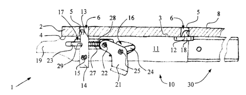
Figs. la and lb are views in elevation illustrating
the means 1 according to the invention in an "open"
position on a flat tool 2 shown in section. Since
the means 1 is elongate in shape similar to a bar,
it is shown in two portions in Figs. la and lb
respectively. Fig. la shows the front part 10 of
the means 1 and the central part 30 thereof partly
in section, whereas Fig. lb shows the rear part 40
for engaging in the central part 30. The general
shape of the means 1 is preferably that of a
straight bar having a narrow cross-section and
disposed with its top edge 3 against the bottom
surface 4 of the flat tool 2. The tool can
typically be an ejection board of a platen press
(not shown).
In a preferred embodiment, the front part 10 inter
alia comprises a body 11 provided with a mechanism
20 for fixing the means 1 on the flat tool 2 by
moving from an "open" position to a "closed"
JBF 3 09
CA 02494215 2005-01-25
position and conversely for withdrawing the means 1
from the flat tool 2.
The means 1 is secured by at least one fixed lug 12
and at least one moving lug 13, both secured to the
means 1 and each adapted to engage a side 5 of an
opening 6 formed for this purpose in the flat tool
2. Each lug has a cutting or pointed end for easy
insertion e.g. into wood. In the preferred
-embodiment, the fixed lug 12 faces the rear and
comprises a protuberance on the body 11 situated at
the rear end thereof against the top edge 3. The
movable lug 13 faces the front so as to point in the
opposite direction to the fixed lug 12. The movable
lug 13 can also move in the longitudinal direction
and constitutes the top part of a stirrup 14 mounted
for swinging around a shaft 15 through the body 11
of the means 1 as illustrated inter alia in Fig. 3.
The movable lug 13 is moved longitudinally by action
of the mechanism 20 which, when in the open
position, brings the stirrup 14 into a preferably
vertical position as illustrated in Fig. la, whereas
in the closed position as illustrated in Fig. 2 the
mechanism 20 forces the lug 13 forwards around its
axis of rotation 15 so that the lug 13 can engage
the flat tool 2 by entering the side 5 of the
corresponding opening 6. For this purpose the
closing and opening mechanism 20 comprises a lever
in the form of a bent handle 21 connected at one end
to a rod 23 by a first joint 22 and connected by its
shank to the end of a bar 24 by a second joint 25.
JBF 309
CA 02494215 2005-01-25
11
As shown more clearly in Fig. la, the bar 24 also
serves as a lever and its opposite end bears on the
bottom of an aperture 16 formed in the body 11 of
the means 1. The rod 23 extends through the stirrup
14 and slides longitudinally in a groove 17 made for
this purpose in the body 11 of the means 1. Between
the first joint 22 and the stirrup 14, the rod 23
has a section surrounded by a resilient means 27
illustrated by a compression spring in Figs. la, 2
and 4. The resilient means or compression strings
bears at the rear against a shoulder 28 of the rod
23 whereas the front rests against the stirrup 14
and pushes it until it abuts a detent pin 29
transversely fixed relative to the rod 23. The
movable lug 13 is thus pressed both by action of the
bent handle 21 when closed and by action of the
resilient means 27.
As illustrated more particularly in Fig. 4, in order
to improve and stabilise the means 1 when placed
upright on its top edge 3, at least one rib 18 is
mounted on the edge in order to form a small
additional bearing surface against the bottom
surface 4 of the flat tool 2.
At least one end 19 of the means 1 is profiled so
that it can be gripped by the position-finding and
clamping device (not shown but provided in the
platen press for holding the flat tool 2 properly in
the machine).
JBF 3 09
CA 02494215 2005-01-25
12
Fig. lb illustrates the rear part 40 of the means 1
according to the invention. The rear part, which
can but need not be detached from the means 1, is
movable in the longitudinal direction relative to
the front part 10, preferably by sliding. To this
end the part comprises inter alia a sliding portion
41 and a tail 42. The sliding portion 41 slides
along the central part 30 of the means 1. For this
purpose, in the preferred embodiment, the central
part 30 is a tubular part with inner dimensions
slightly greater than the outer dimensions of the
sliding portion 41. When therefore the two parts
slide relative to one another, the length of the
means 1 can vary as needed by the user within a
range corresponding to the length of the sliding
travel.
The tail 42 has a lug 43 facing the front and
similar or identical in shape with the fixed lug 12
described previously. The lug 43 is preferably
fixed and serves the same purpose as the fixed lug
12. Advantageouslythe tail also has a rib 18 for
stabilising the means 1. In the preferred
embodiment as illustrated in Fig. lb, the tail
likewise has a fixing mechanism 20 identical with
that in the front part 10 as previously described.
The rear part 40 of the means according to the
invention comprises a stop 45 against which a
locking means belonging to the packaging machine can
bear and push the rear part 40 in the longitudinal
direction. To this end, a cross-bar of the machine
JBF 3 09
CA 02494215 2005-01-25
13
slides on a flat part 44 at the end of the tail 42,
on the bottom edge 7 of the means 1. The bar (not
shown since it forms part of a fixing device outside
the invention) is the clamping means for holding the
flat tool 2 in the machine. When the cross-bar
comes in contact against the stop 45 on the edge 7
at the front of the flat part 44, therefore, it can
push the tail 42 of the means 1 forward so that the
lug 43 is planted in the side 5 of the corresponding
opening 6 and thus entrains the entire flat tool 2
in the same direction until it can be gripped in the
machine via the end 19.
The means 1 according to the invention has the
advantage of being simple, quick and reliable in
use. It can positioned and fixed simply by
inserting the lugs 12, 13 of the front part 10 into
the corresponding openings 6 in the flat tool 2,
adjusting the length of the means 1 and sliding the
rear part 40 along the central part 30 until the lug
43 of the tail 42 also slides into an opening 6,
pressing the top edge 3 of the means 1 against the
bottom surface 4 of the flat tool, and lowering the
bent handle 21 in order to close the fixing
mechanism 20. The means can be equally easily
withdrawn from the flat tool by the same operations
in the reverse sequence. Note in this connection
that the means 1 can be positioned and withdrawn
without any additional tool or other mechanical
part.
JBF 309
CA 02494215 2005-01-25
14
Owing 'to the simplicity of operation and use
thereof, the means can be roughly constructed
without regard to appearance. For example the
joints 22, 25, the shaft 15 and the detent pin 29
can be in the form of simple resilient pins. The
front part 10 and rear part 40 can advantageously be
cut out by machining with a laser, like the aperture
16 and the groove 17 inter alia. The tubular shape
of the central part 30 can be obtained by bending
and welding a plate provided for the purpose. The
front and central parts, like the ribs 18, can
likewise be assembled simply by welding. As can be
seen, therefore, the cost of constructing a
strengthening means of this kind can be reduced to
the minimum without adversely affecting the required
stability.
Note that the openings 6 are preferably square or
rectangular and their sides are advantageously
vertical but can slope slightly or have a particular
profile. The openings 6 can be very easily machined
by a laser, particularly when the flat tools are
made of wood as is generally the case. This method
of machining gives a neat precise cut while keeping
within tolerances which are more than sufficient for
an application of this kind. Owing also to the
action of the resilient means 27 of the fixing
mechanism, the means 1 is firmly fixed without
clearance in the flat tool 2. Advantageously
therefore the openings 6 do not require any tight
tolerances, which advantageously contributes to
reducing the cost of production.
JBF 309
CA 02494215 2005-01-25
Note that the means 1 is clamped by pressing the
rear lug 12 and the front lug 13 into openings 6 by
opposing forces directed towards the exterior of the
flat tool 2. The same clamping effect, however, can
be obtained by opposite forces directed towards the
interior of the tool 2.
As illustrated in Figs. la and lb, as will also be
noted, once the means 1 has been properly fixed to
the flat tool, the lugs 12, 13 and 43 are
advantageously all embedded in the thickness e of
the flat tool 2 and consequently do not project from
the top surface 8 of the said tool. This preferred
arrangement avoids any projecting parts on the top
surface 8 of the flat tool and thus eliminates any
risk of moving parts of the machine catching in the
platen press, such as the gripper bars moving along
the said upper surface. This arrangement also
avoids any risk of injury to the machine operator
who has to use these flat tools, particularly in
operations such as changing the tools during
preparation of the machine.
Although the mechanism 20 of the front part 10 is
preferably reproduced in the rear part 40 of the
means 1, another alternative is to dispose the
mechanism only in the front part or in the rear part
of the means 1 or at another place along the means
1.
JBF 309
CA 02494215 2005-01-25
16
In another variant it may be advantageous to provide
a retaining means for stopping the central and rear
parts sliding relative to one another in order to
limit the length of the extension travel of the
means 1 and also prevent any premature separation of
the two parts during use thereof.
Finally the constituent elements of the means 1 are
preferably made of metal such as steel or aluminium,
though this is not essential. Also, although it
could be different, the general shape of the means 1
is rectangular in section and its thickness depends
mainly on the strength of the material used, the
maximum possible length of the means 1, and the
force which must be absorbed by the flat tool 2 in
order at least to withstand the strongest stresses
for which it has been dimensioned. Finally it is
also possible, while retaining sufficient strength,
to reduce the weight of the means according to the
invention by forming a number of openings in those
portions or parts 10, 30 and 40 which are without
any particular functions.
Numerous improvements can be made to the means
according to the invention within the scope of the
claims.
JBF 309