Note: Descriptions are shown in the official language in which they were submitted.
CA 02494381 2005-01-26
DESCRIPTION
STICK-TYPE COSMETIC CONTAINER
Technical Field
The present invention relates to a stick-type cosmetic
container and, more specifically, to a stick-type cosmetic
container in which only a stick-type cosmetic filled therein
can easily be replaced.
Background Art
A stick-type cosmetic container in which a stick-type
cosmetic filled therein is projected and retracted by rotating
an outer cylinder is widely used as a container for lipsticks
and other cosmetics such as lip cream and concealer because
of its usability or some other reasons.
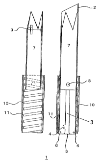
The stick-type cosmetic container in the related art
includes, for example, an outer cylinder 10, a sleeve 2 and
an inner container 7 filled with the stick-type cosmetic with
an outer decorative cylinder and a lid removed, as shown in
Fig. 1. In Fig. 1, the right drawing is a cross-sectional view
substantively showing only the inner container 7 (the stick-type
cosmetic is not shown) , and the left drawing is a cross-sectional
view showing a state in which only the sleeve 2 is removed.
A small projection 8 is provided on the lower portion
1
CA 02494381 2005-01-26
of the outer surface of the inner container 7, and an inner
container guiding groove 3 is formed on the sleeve 2, and a
helical groove 11 is formed on the inner surface of the outer
cylinder 10. The small projection 8 on the inner container
7 moves upward and downward along the inner container guiding
groove 3 on the sleeve 2 in accordance with the rotation of
the helical groove 11 on the outer cylinder 10, and the
stick-type cosmetic is projected and retracted accordingly.
In this manner, the small projection 8 of the inner
container? moves upward and downward along the inner container
guiding groove 3 of the sleeve 2 in accordance with rotation
of the outer cylinder 10. However, if it moves endlessly, the
inner container 7 finally drops out of the sleeve 2, and thus
it is necessary to limit the movement of the small projection
8 on the inner container 7 to a certain range. Therefore, in
the stick-type cosmetic container in the related art, the inner
container 7 is prevented from being dropped out by closing both
ends of the inner container guiding groove 3 or by avoiding
formation of the helical groove 11 to the end of the inner surface
of the outer cylinder.
The stick-type cosmetic container in the related art,
having such structure described above, has no problem when it
is used as a disposable container. However, when refilling
or replacing is considered, it is very inconvenient to use.
In other words, since the inner container is configured not
2
CA 02494381 2005-01-26
to be dropped out, replacement of the inner container itself
has to be done after disassembling the cosmetic container once.
In recent years, in accordance with widespread movement
of resource saving or recycling, cosmetic containers which can
be refilled or replaced are preferred. However, as regards
the stick-type cosmetic container, the container in which only
the stick-type cosmetic can be replaced has not been provided
as a matter of fact in above-mentioned reasons.
Therefore, it is an object of the present invention to
provide a stick-type cosmetic container in which refilling and
replacement can easily be performed, while the risk of dropping
of the inner container in normal use can be avoided.
Disclosure of Invention
Having been dedicated to studying means for solving the
problems described above, the present inventors completed the
present invention from such idea that both of refilling and
replacing, and prevention of dropping of the inner container
can be realized simultaneously by utilizing such characteristic
that the inner container moves upward and downward along one
of the inner container guiding groove by the helical groove
formed on the inner surface of the outer cylinder.
In other words, the present invention provides a
stick-type cosmetic container including an outer cylinder, a
sleeve, and an inner container, in which the stick-type cosmetic
3
CA 02494381 2008-01-30
28567-11
can be filled, wherein a small projection formed on the
inner container is guided along an inner container guiding
groove formed on the sleeve, and is moved upward and
downward by a helical groove formed on the inner surface of
the outer cylinder for projecting and retracting the
stick-type cosmetic filled in the inner container,
characterized in that the lower end of the inner container
guiding groove formed on the sleeve is opened and a
retaining mechanism of the small projection is provided on
the lower portion of the inner container guiding groove.
In one embodiment of this aspect of the present
invention, there is provided a stick-type cosmetic container
comprising an outer cylinder, a sleeve, an inner container
in which a stick-type cosmetic can be filled, a small
projection provided on the inner container being guided by
an inner container guiding groove formed on the sleeve, the
small projection moving upward and downward along a helical
groove formed on the inner surface of the outer cylinder,
and the stick-type cosmetic filled in the inner container
being projected and retracted, wherein a lower end of the
inner container guiding groove formed on the sleeve is
opened and a recess for storing the small projection is
provided at a lower portion of the inner container guiding
groove as a retaining mechanism for the small projection and
a stop point for the small projection is provided at a lower
portion of the recess.
In a further embodiment of the stick-type cosmetic
container, a lower end of the inner container guiding groove
formed on the sleeve is opened and a locking projection
corresponding to a locking notch formed on the small
projection is provided at a lower portion of the inner
container guiding groove as a retaining mechanism for the
small projection.
4
CA 02494381 2008-01-30
28567-11
The present invention also provides a method of
preparing the stick-type cosmetic wherein the stick-type
cosmetic container described above is used and the cosmetic
is filled from the bottom portion of the container.
Brief Description of the Drawings
Fig. 1 is a drawing showing a structure of a
stick-type cosmetic container in the related art.
Fig. 2 is a drawing showing a structure according
to an embodiment of a stick-type cosmetic container
according to the present invention. An inner container is
located at the uppermost position.
Fig. 3 is a drawing showing a configuration of a
sleeve used in the stick-type cosmetic container shown in
Fig. 2.
Fig. 4 is a drawing showing the shape of the inner
container
4a
CA 02494381 2005-01-26
used in the stick-type cosmetic container shown in Fig. 2.
Fig. 5 is a drawing showing the movement of a small
projection and the relation between an inner container guiding
groove and a small projection storage recess.
Fig. 6 is a drawing showing a state in which the inner
container is moved partway downward in the stick-type cosmetic
container shown in Fig. 2.
Fig. 7 is a drawing showing a state in which the inner
container is moved downward and the small projection is stored
in the small proj ection storage recess in the stick-type cosmetic
container shown in Fig. 2.
Fig. 8 is a drawing of a stick-type cosmetic container
according to the present invention showing a configuration in
which the top surface of the small projection provided on the
inner container and the inner surface of an outer cylinder come
into contact with each other.
Fig. 9 is a cross-sectional view showing a contact state
between the top surface of the small projection and the inner
surface of the outer cylinder in Fig.8.
Fig. 10 is a drawing showing a configuration in which
a stop point is provided on the sleeve which constitutes the
present invention.
Fig. 11 is a partly enlarged drawing showing the positional
relation between the small projection storage recess and the
stop point in a state in which the stop point is provided on
CA 02494381 2005-01-26
the sleeve.
Fig. 12 is a drawing showing an embodiment of a sealing
device.
Fig. 13 is a drawing showing an example of a flow of using
a stick-type cosmetic container 1 of the present invention,
filling cosmetic into the stick-type cosmetic container 1, and
then conducting a test by bringing the stick-type cosmetic
outwardly of the container, and returning the cosmetic again
into the container.
Fig. 14 is a drawing showing an example of the shape of
the bottom.
Fig. 15 is a drawing showing the structure of another
embodiment of the stick-type cosmetic container of the present
invention. The inner container is located at the lowermost
position.
Fig. 16 is a drawing showing the shapes of the sleeve,
the inner container, and the outer cylinder used in the
stick-type cosmetic container shown in Fig. 15.
Fig. 17 is a drawing showing the relation between the
angle of a helical groove and the angle of a locking surface
in the embodiment shown in Fig. 15.
Fig. 18 is a drawing showing a configuration in which
the distal end of locking surface is moved upward (the state
in which the angle formed between the guiding groove and the
locking surface is an acute angle).
6
CA 02494381 2005-01-26
Fig. 19 is a drawing showing the structure of an embodiment
in which the locking projections are provided at two levels.
The inner container is located at the lowermost position.
Fig. 20 is a drawing showing a state in which the inner
container is at the lowermost position in normal use in the
embodiment shown in Fig. 19.
Fig. 21 is a drawing showing the shapes of the sleeve
and the inner container used in the stick-type cosmetic container
according to the embodiment shown in Fig. 19.
Fig. 22 is a drawing showing the structure in which two
small projections are provided. The inner container is located
at the lowermost position.
Fig. 23 is a drawing showing a state in which the inner
container is at the lowermost position in the normal use in
the embodiment shown in Fig. 22.
Fig. 24 is a drawing showing the shapes of the sleeves
and the inner container used in the stick-type cosmetic container
in the embodiment shown in Fig. 22.
Fig. 25 is a drawing showing a configuration in which
part of the inner container guiding groove is notched at the
position corresponding to the position ofthe locking projection
on the opposite side.
Fig. 26 is a drawing showing the shapes of the sleeves
and the inner container used in the stick-type cosmetic container
in the embodiment shown in Fig. 25.
7
CA 02494381 2005-01-26
Best Mode for Carrying Out the Invention
Hereinafter, referring now to the drawings showing some
embodiments of the present invention, the present invention
will be described further in detail. However, the present
invention is not limited to these embodiments.
Fig. 2 is a drawing showing the structure of an embodiment
of a stick-type cosmetic container according to the present
invention. The drawing on the right side is a cross-sectional
view substantively showing only an inner container, and the
drawing on the left side is a cross-sectional view showing a
state in which only a sleeve is removed (however, the stick-type
cosmetic is not shown) . In the drawing, reference numeral 1
designates the stick-type cosmetic container, reference
numeral 2 designates the sleeve, reference numeral 3 designates
an inner container guiding groove, reference numeral 4
designates a small projection storage recess, reference numeral
5designates a guiding groove end, reference numeral6designates
an inner container stopper, reference numeral 7 designates an
inner container, reference numeral 8 designates a small
projection, reference numeral 9 designates a cosmetic holding
projection, reference numeral 10 designates an outer cylinder,
and reference numeral 11 designates a helical groove,
respectively.
Though the stick-type cosmetic container 1 according to
8
CA 02494381 2005-01-26
the present embodiment basically includes the outer cylinder
formed with the helical groove 11 formed on the inner surface
thereof, the sleeve 2, and the inner container 7 for
accommodating the stick-type cosmetic as in the related art
described in conjunction with Fig. 1, it differs in the shape
of the sleeve and the fact that the helical groove 11 is formed
to the end.
In other words, as seen in the shape of the sleeve 2 used
in the present embodiment shown in Fig. 3, it differs from the
sleeve used in the stick-type cosmetic container in the related
art in that the inner container guiding groove 3 of the sleeve
2 is opened at the lower end 5, in that the small projection
storage recess 4 is provided at the lower portion of the inner
container guiding groove 3, and in that the inner container
stopper 6 is provided at the lower portion of the sleeve 2.
A cross-section of the inner container 7 used in
combination therewith is shown in Fig. 4. The inner container
has a cylindrical shape pointed only at the distal end, and
includes the cosmetic holding projection 9 at the boundary
between the pointed portion and the cylindrical portion for
holding the filled stick-type cosmetic in the inner container
7. In addition, at the lower portion of the cylindrical portion,
the small projection 8 of small cylindrical shape is provided.
In the stick-type cosmetic container 1 of the present
invention, the mechanism in which the inner container 7 does
9
CA 02494381 2005-01-26
not drop out through the lower portion although the lower end
of the inner container guiding groove 3 is opened, and the
helical groove 11 of the outer cylinder 10 is formed to the
end is as follows.
By rotating the outer cylinder 10 of the stick-type
cosmetic container 1 in the state shown in Fig. 2 while holding
the sleeve 2 to the left, the helical groove 11 formed on the
inside of the outer cylinder 10 provides a force to the small
projection 8 of the inner container 7 in the lower left direction.
However, since the small projection 8 is guided by the inner
container guiding groove 3 of the sleeve 2, it cannot be moved
leftward, and thus moves only downward.
Fig. 5 shows this state of movement. In the drawing,
the small projection 8 shown by dotted circles is exerted with
a force in the lower left direction by the helical groove 11
shown by the oblique lines. However, since the leftward
movement is restrained by the inner container guiding groove
3, it moves downward along the left end of the inner container
guiding groove 3. Fig. 6 shows the midstage of this movement
in the same manner as Fig. 2 (however, the outer cylinder portion
is omitted in the drawing on the right side).
By rotating the outer cylinder leftward in this manner,
the small prof ection 8 is moved downward, and the inner container
7 also moves downward correspondingly. However, since the
small projection storage recess 4 is provided at the position
CA 02494381 2005-01-26
near the lower end 5 of the inner container guiding groove 3,
a leftward force, which has been restrained by the left end
of the inner container guiding groove 3 until that moment, is
exerted, and thus the small projection 8 is stored and held
in the small projection storage recess 4, not at the position
shown by a circle of the chain double-dashed line in Fig. 5.
Therefore, since the small projection 8 is restrained in the
small projection storage recess 4, it cannot be moved further
downward even when an attempt is made to further rotate the
outer cylinder 10. Fig. 7 shows this state in the same manner
as Fig. 2 (however, the outer cylindrical portion is omitted
in the drawing on the right side).
In addition, when the inner container stopper 6 is provided
at the lower end of the sleeve 2, it serves as a resistance
with respect to the descending inner container 7, and hence
the force acting on the small projection 8 exerted from the
right side is increased, and thus the small projection 8 can
easily enter into the small projection storage recess 4. The
inner container stopper 6 may not only be the one which completely
stop the inner container 7, but also be the one that generates
a resistance to the downward movement when in contact. For
example, it can be provided by forming a small projection of
a convex shape on the inner side of the lower end of the sleeve
2.
As another means for allowing easy entrance of the small
11
CA 02494381 2005-01-26
projection 8 into the small projection storage recess 4, there
is a method of bringing at least part of the top surface 8a
of the small projection 8 and the inner surface l0a of the outer
cylinder 10 into contact with each other as shown in Fig. 8.
According to this method, when the small projection 8 moves
upward and downward in the inner container guiding groove 3,
at least part of the top surface 8a of the small projection
8 and the inner surface l0a of the outer cylinder 10 keep
constantly in contact with each other and hence a resistance
is generated as shown in Fig. 9. Therefore, a force acting on
the small projection 8 exerted from the right side is increased
and thus it can easily enter into the small projection storage
recess 4. When implementing the present embodiment, it is
preferable to provide the outer cylinder 10 having the same
diameter from the top to the bottom, and in this case, it is
preferable to reduce a thickness t of the outer cylinder 10
to provide resiliency. Means for bringing the part of the top
surface 8a of the small projection 8 into contact with the inner
surface 10a of the outer cylinder 10 includes a method of setting
down the center portion of the top surface 8a and allowing only
the peripheral portion to come in contact therewith, or a method
of providing a rib at the center and allowing only the rib to
come into contact therewith.
Subsequently, in order to bring the stick-type cosmetic
up from the stick-type cosmetic container 1 in the state shown
12
CA 02494381 2005-01-26
in Fig. 7 (to move upward) , the outer cylinder 10 may be rotated
rightward, in contrast to the means described above. The small
projection 8 stored and held in the small projection storage
recess 4 receives a force in the upper right direction by the
force of the helical groove 11 formed on the outer cylinder
10, and is moved upward along the right end of the inner container
guiding groove 3, and then the inner container 7 also moves
upward correspondingly.
With this mechanism, the inner container 7 moves upward
and downward in the sleeve 2 without dropping out. However,
when the stick-type cosmetic filled in the inner container 7
has used up, it can easily be replaced together with the inner
container 7 by following means.
In a first place, the inner container 7 is moved to the
lowermost position, and the small projection 8 is stored in
the small projection storage recess 4. Then, by suitable means
such as the usage of a jig, the small projection 8 on the inner
container 7 is moved from the small projection storage recess
4 to the position shown by the circle of the double-dashed line
in Fig. 5. When it is moved to this position, since the lower
end 5 of the inner container guiding groove 3 is opened, and
thus the spent stick-type cosmetic can easily be taken out
together with the inner container 7 by surmounting the resistance
of the inner container stopper 6 by the operation of the jig.
Subsequently, replacement of the stick-type cosmetic is
13
CA 02494381 2005-01-26
completed by inserting a new stick-type cosmetic filled in the
inner container from the bottom of the stick-type cosmetic
container 1 and storing the small projection 8 into the small
projection storage recess 4 by the use of the jig again.
In the stick-type cosmetic container 1 of the present
invention, it is possible to fill the stick-type cosmetic in
the inner container 7 in advance and mounting it in the container
1. However, it is also possible to mount the inner container
7 without having the stick-type cosmetic filled therein into
the stick-type cosmetic container land then filling the cosmetic
in the melted state from the bottom of the cosmetic container
1 into the sleeve 2 or the inner container 7 to a predetermined
level and making it solid by cooling or the like to prepare
the stick-type cosmetic.
The shape of the sleeve 2 of the stick-type cosmetic
container 1 suitable for the preparing method of the latter
is shown in Fig. 10.
The sleeve 2 shown in Fig. 10 further includes a stop
point 14 at the lower portion of the small projection storage
recess 4 formed on the inner container guiding groove 3 (In
this embodiment, the small projection 8 is placed at the position
marked with a hatched circle in the drawing when being filled) .
Fig. 11 is a partial enlarged drawing showing the positional
relation between the small projection storage recess 4 and the
stop point 14 in the present embodiment. In the present
14
CA 02494381 2005-01-26
embodiment, two small projections 14a are provided continuously
at the lower portion of the small projection storage recess
4 in the inner container guiding groove 3, and the portion
interposed between the proj ections 14a is used as the stop point
14. Reference sign "X" designates the distance between the
center of the small projection storage recess 4 and the center
of the stop point 14.
The sleeve 2 is used with sealing device 15 shown in Fig.
12, which is to be mounted to the opening thereof, and is capable
of bringing the distal end of the sleeve and the distal end
surface of the stick-type cosmetic flush with each other.
In other words, in preparing the stick-type cosmetic,
when the cosmetic was filled using the normal cover, there arose
the problem in that the cosmetic leaks from the gap of the cover,
and attached to the edge of the opening, which lowered the
commercial value.
Such drawback can be resolved by filling the cosmetic
so as not to reach the opening of the sleeve, that is, by using
a cap which is set back inwardly. However, when the stick-type
cosmetic is not filled up to the level of the opening of the
sleeve when starting to use, the consumer may think that the
filling amount is not sufficient, which is not commercially
desirable as a commodity design.
In order to cope with such problems, the stop point 14
which is capable of fixing the small projection 8 temporarily
CA 02494381 2005-01-26
is provided on the inner container guide groove 3 of the sleeve
2 downwardly of the small projection storage recess 4, and the
sealing device 15 is mounted to the opening of the sleeve 2
when filling and molding the cosmetic. In addition, it was
found that the positional relation between the distal end of
the sleeve and the distal end surface of the cosmetic can be
controlled freely and aligned by providing inward setbacks on
the sealing device 15 corresponding to the interval between
the small projection storage recess 4 and the stop point 14.
Fig. 12 is an embodiment of the sealing device used for
the above-described object, in which A is a perspective view
and B is a cross-sectional view. In the drawings, reference
numeral 15a designates an insertion portion, reference numeral
15b designates a fitting portion, and reference numeral 15c
designates an air hole.
Fig. 13 shows an example of flow including the steps of
filling the cosmetic in the stick-type cosmetic container 1
using the sleeve 2 shown in Fig. 10 and Fig. 11 and the stick-type
cosmetic container 1 including the sealing device 15 shown in
Fig. 12 to prepare the stick-type cosmetic, inspecting the
stick-type cosmetic by bringing it up, and returning the cosmetic
into the cosmetic container 1.
In other words, the sealing device 15 is placed on an
opening 2a of the sleeve in a state with the small projection
8 (black portion in Fig. 13) stored in the stop point 14, and
16
CA 02494381 2005-01-26
the opening 2a of the sleeve is clamped between the insertion
portion 15a and the fitting portion 15b of the sealing device
15 for fixing and sealing. Subsequently, by inverting the
cosmetic container 1 so as to be upside down, and filling the
stick-type cosmetic in the melted state from the bottom thereof,
the cosmetic can be filled in the hatched portion, and may be
cooled and solidified so that the stick-type cosmetic 16 is
formed and prepared (A in Fig. 13).
When the sealing device 15 is removed from the opening
2a of the sleeve after filling and molding of the cosmetic,
the stick-type cosmetic 16 is obtained in a state in which the
portion of the sleeve on the distal end side is not filled with
the cosmetic by the length Y (See the drawing B). Then when
the outer cylinder 10 is rotated rightward, the small projection
8 moves away from the stop point 14 and moves along the right
end of the inner container guiding groove 3 upward without being
stored in the small projection storage recess 4 positioned on
the left side of the guiding groove 3. At this time, the
stick-type cosmetic 16 moves away from the surface of the sleeve
2, moves upward in the state of being fixed to the inner container
7, and is brought up from the sleeve opening 2a. (See the drawing
C. An arrow indicates the direction in which the stick-type
cosmetic 16 advances. It is the same in the drawing E).
The stick-type cosmetic 16 is inspected in the state of
being bought up to the maximum (See the drawing D) . After the
17
CA 02494381 2005-01-26
inspection, by rotating the outer cylinder 10 toward the left,
the small projection 8 moves downward along the left end of
the inner container guiding groove 3, and the stick-type cosmetic
16 also moved downward according to the movement of the inner
container 7 (See the drawing E) Then, the small projection
8 is finally stored and held in the small projection storage
recess 4 provided at the lower left of the guiding groove 3
(See the drawing F).
In this manner, according to the present embodiment, the
position of the small projection 8 (at the stop point 14) when
starting the filling operation differs from the position of
the small projection 8 (in the small projection storage recess
4) at the time of shipping. In this case, by setting the distance
X between the stop point 14 and the small projection storage
recess 4 to meet the length of the sealing device 15 (that is,
the unfilledportion Y at the distal end) , the distal end surface
of the stick-type cosmetic 16 and the opening 2a of the sleeve
preferably coincide with each other when the small projection
8 is stored in the small projection storage recess 4. In addition,
since the sealing device 15 which is set back inwardly is used,
the cosmetic does not leak from the edge of the sleeve opening
2a when filling the cosmetic, and hence the problem of stain
at the opening 2a may be avoided.
The shape of the stop point 14 in the present embodiment
is not limited as long as it can stop the small projection 8
18
CA 02494381 2005-01-26
when filling the cosmetic. However, the shape which fixes the
small projection 8 and, simultaneously, allows it to move easily
when moving upward along the right end of the inner container
guiding groove 3 is preferable. With such shape, when bringing
up the stick-type cosmetic 16 (moving the small projection 8
upward) by rotating the outer cylinder 10 rightward after filling
and molding the cosmetic, the small projection 8 is subjected
to the force in the right upward direction, so that the stick-type
cosmetic 16 does not rotate by itself when being brought up,
and the upwardmovement along the right end of the inner container
guiding groove 3 is done smoothly.
Another reason why the embodiment described above is
preferable is as follows. Since the cosmetic filled in the
stick-type cosmetic container 1 slightly shrinks when being
cooled and solidified, the outer surface of the cosmetic normally
comes away from the inner surface of the sleeve. However, the
cosmetic and the sleeve may stay in tight contact on rare occasion.
In such a state, when a rotational force is exerted to the cosmetic
in order to bring up the stick-type cosmetic by rotating the
outer cylinder 10 rightward, the cosmetic may disadvantageously
be broken since the sleeve 2 and the cosmetic are in tight contact
with each other. On the other hand, by employing the stop point
14 in the configuration as described above, the small projection
8 received only the upward force, and thus the cosmetic can
be peeled off the inner surface of the sleeve without rotating
19
CA 02494381 2005-01-26
the stick-type cosmetic when being brought up.
The stop point 14 is preferably formed by machining the
lower portion of the small projection storage recess 4 in the
inner container guiding groove 3 into the configuration shown
in Fig. 10 and Fig. 11 as described in the embodiment described
above. Though not shown, it is also possible to form the lower
end of the small projection storage recess 4 so as to overhang
into the inner container guiding groove 3. In this
configuration as well, the small projection 8 can easily be
moved along the right end of the inner container guiding groove
3.
The shape of the sealing device 15 in the present
embodiment is not specifically limited as long as it can close
the opening of the sleeve 2. However, the length Y preferably
coincides with the distance X between the small projection
storage recess 4 and the stop point 14. In addition, like the
configuration shown in Fig. 12, by forming the suitable air
hole 15c for allowing air ventilation, air can easily be flown
into the gap between the inner surface of the sleeve 2 and the
cosmetic when the cosmetic shrinks in response to cooling at
the time of filling and molding, and hence peeling off of the
cosmetic is preferably performed smoothly. In addition, it
is further preferable to employ a capsule-shape, since it can
be removed easily.
Though the number of the air hole 15c is not specifically
CA 02494381 2005-01-26
limited, forming three or four air holes 15c is preferable in
view of usability and manufacturability of the sealing device
15.
The position of the small projection 8 at the stop point
14 shown in Fig. 11 is slightly displaced in the direction of
rotation from the position of the small proj ection storage recess
4 when the stick-type cosmetic is stored. This configuration
has no problem as long as the shape of the distal end of the
stick-type cosmetic is rotational symmetry with respect to the
centerline of the stick-type cosmetic. However, in the case
where the distal end is inclined as shown in Fig. 10, the direction
of the end surface of the opening of the sleeve 2 and the direction
of the end surface of the stick-type cosmetic when the stick-type
container is stored do not coincide due to the above-described
displacement in the direction of rotation, which may result
in rough finish. In such case (in the configuration shown in
Fig. 10) , it is preferable to correct the shape of the sealing
device 15 to the extent corresponding to such displacement in
advance so that both of the surfaces coincide with each other.
In the stick-type cosmetic container 1 of the present
invention, since there are cases inwhichthestick-type cosmetic
is taken in and out from the bottom, it is necessary that the
bottom is opened to some extent. However, since such state
does not present good appearance, the bottom 12 may be formed,
for example, into the shape shown in Fig. 14, and adhered with
21
CA 02494381 2005-01-26
a sticker in normal use. The size of the hole on the bottom
12 may be slightly larger than the inner container 7, and a
notch 13 maybe formed so as to correspond to the small projection
8.
It will be convenient to mark the product number, the
color tone, and the like on the sticker to be adhered on the
bottom 12 when purchasing the stick-type cosmetic for
replacement.
Another configuration of the small projection retaining
mechanism of the stick-type cosmetic container of the invention
is shown in Fig. 15 to Fig. 16. In the drawings, reference
numeral 101 designates a sleeve, reference numeral 102
designates an inner container guiding groove, reference numeral
103 designates an outer cylinder, reference numeral 104
designates a helical groove, reference numeral 105 designates
an annular projection, reference numeral 106 designates a recess
groove, reference numeral 107 designates an inner container,
reference 108 designates a small projection, reference numeral
112 designates a locking projection, reference numeral 113
designates a locking surface, reference numeral 114 designates
a gentle slope, and reference numeral 115 designates a locking
notch.
In this configuration, the retaining mechanism including
the locking projection 112 formed at the lower portion of the
inner container guiding groove 102 and the locking notch 115
22
CA 02494381 2005-01-26
formed at the position corresponding to the locking projection
112 of the small projection 108 is provided.
The locking projection 112 is formed to make the width
of the inner container guiding groove 102 smaller than the
diameter of the small projection 108 on the inner container
107, and is formed on the side surface toward which the small
projection 108 is pushed against by the helical groove 104 when
the inner container 107 is moved downward (the left side in
Fig. 15) . The upper surface of the locking projection 112 is
formed with a substantially horizontal locking surface 113 so
as to fit to the locking notch 115 of the small projection 108.
Since a force to push the small projection 108 toward the left
is generated when the small projection 108 is moved downward,
the small projection 108 cannot climb over the locking projection
112, and hence the inner container 107 is prevented from dropping
out of the sleeve 101.
It is necessary to define the angle formed between the
locking surface 113 and the upper portion of the inner container
guiding groove 102 (angle A in the drawing) smaller than the
angle formed between the helical groove 104 and the upper portion
of the inner container guide groove 102 (angle B in the drawing)
as shown in Fig. 17. The lower surface 114 of the locking
projection 112 is preferably a gentle slope so that the small
projection 108 can easily climb over the locking projection
112 by broadening the width of the inner container guiding groove
23
CA 02494381 2005-01-26
102 when setting the inner container 107 to the sleeve 101.
In the stick-type cosmetic according to the present
invention, it is necessary to allow the sleeve 101 and the outer
cylinder 103 to rotate freely but keep them not to be dropped
out easily. In order to do so, for example, a mechanism in
which the annular projection 105 formed into a ring-shape at
the substantially center of the sleeve 101 is clamped in the
recess groove 106 formed on top of the outer cylinder 103 as
shown in Fig. 16 may be provided.
Though the small projection 108 in this configuration
is not specifically limited, it is preferable to form it into
a small column in order to ensure fitting between the locking
notch 115 and the locking projection 112. Alternatively, as
shown in Fig. 18, the distal end of the locking surface 113
may be raised in order to enhance the effect of holding the
small projection 108.
In the retaining mechanism described above, it is also
possible to provide a plurality of either small projections
108 or locking notches 115 to provide a plurality of holding
positions.
For example, Fig. 19 to Fig. 21 show the configuration
in which the locking projections 112 are provided at two levels.
In this configuration, the single small projection 108
is provided on the inner container 107, while the upper locking
projection 112a and the lower locking projection 112b are
24
CA 02494381 2005-01-26
provided at two levels aligned in the vertical direction, and
the respective locking projections are formed respectively with
locking surfaces 113a, 113b and gentle slopes 114a, 114b.
In the cosmetic storage container having two locking
projections aligned in the vertical direction as described above,
the cosmetic can be filled fromthe bottom finelyby the following
procedure. When filling the cosmetic into the container, as
shown in Fig. 19, the inner container 107 is brought down to
the position where the small projection 108 is locked with the
lower locking projection 112b, then sealing device (not shown)
is placed on the opening at the distal end of the sleeve 101,
and then the sealing device is fixed and sealed. Subsequently,
by inverting the cosmetic container so as to be upside down,
and filling the stick-type cosmetic in the melted state therein
from the bottom, the cosmetic can be filled to the predetermined
level, and may be cooled and solidified to mold and prepare
the stick-type cosmetic.
The stick-type cosmetic is solidified and molded in this
manner. However, when the sealing device for sealing the
opening at the distal end of the sleeve 101 having a length
corresponding to the distance between the two locking
projections is employed, the sealing device is removed once,
then the inner container 107 is brought upward until it passes
over the position where the small projection 108 is locked with
the upper locking projection 112a for investigating whether
CA 02494381 2005-01-26
or not there is abnormality in the solidified cosmetic, and
then is again brought down. Consequently, the small projection
108 is locked with the upper locking projection 112a as shown
in Fig. 20, and is stopped and held there. Since the distal
end surf ace of the stick-type cosmetic at this time substantially
coincides with the distal end of the sleeve and, in addition,
the surface thereof is as smooth as the surface of the sealing
device, it can be provided as a final product.
Examples of the sleeve 101 and the inner container 107
used in this configuration are shown in Fig. 21.
As another example of the retaining mechanism in which
the plurality ofholding positions are provided, a configuration
in which two small projections including an upper small
projection 108a and a lower small projection 108b are provided
as small projections including the locking notches 115 as shown
in Fig. 22 and Fig. 24 may be provided.
The operational mechanism in this configuration is
basically the same as the configurations described above, and
when filling the cosmetic into the container, the inner container
107 is brought down to the position where the upper small
projection 108a is locked with the locking projection 112 as
shown in Fig. 22, and the sealing device (not shown) is placed
on the opening at the distal end of the sleeve 101, and the
sealing device is fixed and sealed. Subsequently, by inverting
the cosmetic container to be upside down, and filling the
26
CA 02494381 2005-01-26
stick-type cosmetic in the melted state from the bottom, the
cosmetic can be filled to the predetermined level, and may be
cooled and solidified to mold and prepare the stick-type
cosmetic.
When the sealing device having a length corresponding
to the distance between the two small projections is used when
solidifying and molding, the sealing device is removed, the
inner container 107 is brought upward until it passes over the
position where the lower small projection 108b is locked with
the locking projection 112 once for investigating whether or
not there is abnormality in the solidified cosmetic, and then
is again brought down. Consequently, the lower small
projection 108b is locked with the locking projection 112 as
shown in Fig. 23, and is stopped and held there. Since the
distal end surface of the stick-type cosmetic at this time
substantially coincides with the distal end of the sleeve and,
in addition, the surface thereof is as smooth as the surface
of the sealing device, it can be provided as a final product.
Examples of the sleeve 101 and the inner container 107
used in this configuration is shown in Fig. 24.
In the retaining mechanism including the locking
projection 112 and the small projection 108 having the locking
notch 115, a recess 120 may be formed by removing part of the
inner container guiding groove 102 at the position corresponding
to the locking projection 112 on the opposite side as shown
27
CA 02494381 2005-01-26
in Fig. 25 and Fig. 26.
The recess 120 is formed for facilitating passage of the
small projection 108 through the portion of the locking
projection 112 when moving the inner container 107 upward, and
thus the inner container 107 can easily be mounted into the
sleeve 101.
The stick-type cosmetic container of the present
invention thus obtained can be prepared as substantially the
same products as the stick-type cosmetic container which has
been provided in the related art in material, size and shape
except for the shape of the sleeve 2 or 101, the fact that the
helical groove 11 or 111 on the outer cylinder is formed to
the end, and the shape of the small projection according to
the second embodiment. In other words, the distal end of the
inner container may not be the pointed shape, but may be other
shapes, andmaterials for the sleeve 2 or 101, the inner container
7 or 107, and the outer cylinder 10 or 110 may be various types
of metal or plastic as in the related art. In addition, it
is also possible to cover or coat the outer surface of the outer
cylinder with metal to obtain a decorative cylinder, or to coat
the same in various manners. A lid may be provided. Materials
to be used for these members maybe paper or ceramics in addition
to the metal or plastic, as long as it can keep the shape.
Industrial Applicability
28
CA 02494381 2005-01-26
According to the stick-type cosmetic container of the
present invention, the inner container does not drop out when
in use, but can easily be replaced by the use of a simple jig
when the stick-type cosmetic is completely used.
Therefore, it can be effectively used for the cosmetics
such as lipstick, lip cream, concealer, skin whitening stick,
sun screen stick as a stick-type cosmetic container which
realizes resource saving and recycling.
29