Note: Descriptions are shown in the official language in which they were submitted.
CA 02494714 2012-05-29
52132-24
DEVICE WITH INFUSION HOLES FOR IMAGING INSIDE A BLOOD VESSEL
FIELD OF THE INVENTION
The field of the invention relates generally to devices for imaging inside
a blood vessel and, more specifically, to imaging devices such as catheters
capable
of liquid infusion.
BACKGROUND OF THE INVENTION
Catheter imaging technology has long been recognized for its potential
use in medical applications that involve visualizing the structure and
conditions of a
body. For example, catheter imaging technology may be used to locate anatomy,
position diagnostic and therapeutic medical devices, and monitor surgery and
surgical results.
Existing catheter imaging techniques include optical coherence domain
reflectometers (OCDR), optical coherence tomography (OCT), acoustic imaging,
intravascular ultrasound (IVUS), and optical triangulation.
Examples of utilizing OCDR to perform optical imaging are described in
U. S. Patent Nos. 5, 459, 570 and 5, 321, 501, both issued to Swanson et al.
An example of utilizing acoustic imaging is described in U. S. Patent
No. 4, 951, 677, issued to Crowley et al.
Generally, these techniques involve emitting energy, such as light or
sound, directed at a particular object and then detecting the energy's
reflection or
echo. Those skilled in the art will appreciate, however, that when using the
techniques that emit high-frequency energy, such as near-infrared light or
high-
frequency ultrasound, in a body, blood may present a problem. This is due
primarily
to the presence of erythrocytes, or red blood cells (RBCs). The RBCs are of
the size
that interfere with short waves such as those of the high frequency energy.
For
1
CA 02494714 2012-05-29
52132-24
example, in the case of OCT, blood may cause optical attenuation due to
absorption
and scattering.
In view of these limitations of conventional imaging catheters, an
improved imaging device is needed.
SUMMARY OF THE INVENTION
An example imaging device includes an elongated member, having
distal and proximal ends, an axis, a lumen along the axis, and an outer
surface. The
imaging device may be, for example, an imaging guidewire, imaging catheter,
imaging probe, or imaging trocar. In an example embodiment of an improved
device,
an infusion hole or a plurality of infusion holes are defined along the axis
of said
elongated member between the lumen and the outer surface. The plurality of
infusion holes may be tapered from the outer surface to the lumen. Further,
the
plurality of infusion holes may be angled outwardly toward the proximal end of
the
elongated member. Preferably, the improved imaging device infuses liquid
efficiently
and thoroughly into a blood stream while substantially preventing any radial
jetting.
Some embodiments disclosed herein relate to an imaging device
comprising: an elongated member having distal and proximal ends, an axis, and
an
outer surface; a lumen extending along the axis; a plurality of infusion holes
defined
in the elongated member, the plurality of infusion holes extending between the
lumen
and the outer surface, wherein the plurality of infusion holes have inner
walls
extending from the lumen to the outer surface that are angled outwardly toward
one
end of the elongated member; and an imaging window that is transparent to
imaging
energy and adapted to pass the imaging energy to an imaging area located
distally to
the plurality of infusion holes.
Some embodiments disclosed herein relate to a catheter assembly
comprising: an elongated member having distal and proximal ends and an outer
2
CA 02494714 2012-05-29
52132-24
surface; a lumen extending in and along the elongated member; a plurality of
holes
extending between the outer surface and the lumen of the elongated member,
wherein the plurality of infusion holes have inner walls extending from the
lumen to
the outer surface that are angled outwardly toward one end of the elongated
member;
an imaging window that is transparent to imaging energy and adapted to direct
the
imaging energy to an imaging area located distally to the plurality of
infusion holes; a
sidearm adapter coupled with the proximal end of the elongated member, the
sidearm adapter adapted to allow a liquid to be injected into the lumen of the
elongated member; and a connector assembly coupled with the sidearm adapter.
Some embodiments disclosed herein relate to use of an imaging device
for imaging a flow within a bloodstream, having a flow direction, of a blood
vessel of a
body, the imaging device having an elongated member with a central axis and an
outer surface, a lumen extending along the axis, a plurality of infusion holes
defined
in the elongated member and extending between the lumen and the outer surface,
wherein the plurality of infusion holes have inner walls extending from the
lumen to
the outer surface that are angled outwardly toward one end of the elongated
member,
and an imaging window that is transparent to imaging energy and adapted to
pass
the imaging energy to an imaging area located distally to the plurality of
infusion
holes; wherein the imaging device is for insertion into the blood vessel of
the body;
wherein a liquid is for introduction into the imaging device and for injection
through
the infusion holes of the imaging device into the bloodstream of the blood
vessel
against the flow direction of blood in the vessel; and wherein the imaging
window of
the imaging device is for performing imaging through.
Other systems, methods, features and advantages of the invention will
be or will become apparent to one with skill in the art upon examination of
the
following figures and detailed description. It is intended that all such
additional
systems, methods, features and advantages be included within this description,
be
within the scope of the invention, and be protected by the accompanying
claims.
2a
CA 02494714 2012-05-29
52132-24
BRIEF DESCRIPTION OF THE DRAWINGS
The components in the figures are not necessarily to scale, emphasis
instead being placed upon illustrating the principles of the invention.
Moreover, in the
figures, like reference numerals designate corresponding parts throughout the
different views. However, like parts do not always have like reference
numerals.
Moreover, all illustrations are intended to convey concepts, where relative
sizes,
shapes and other detailed attributes may be illustrated schematically rather
than
literally or precisely.
FIG. 1 is an illustration of a preferred embodiment of an improved
imaging device in the form of a catheter.
FIG. 2 is an illustration of a portion having infusion holes of the
preferred embodiment of an improved imaging catheter.
FIG. 3 is an illustration of a preferred embodiment of an improved
imaging catheter assembly.
FIG. 4 is an illustration of a catheter connector assembly.
DETAILED DESCRIPTION OF THE PREFERRED EMBODIMENTS
FIG. 1 is an illustration of a preferred embodiment of an improved
imaging device. In this example, the imaging device is an OCT imaging catheter
100.
However, the imaging device can be an imaging guidewire, imaging probe,
imaging
trocar, or other imaging devices. For the sake of convenience, the preferred
embodiment is described as an imaging catheter 100, but this is not intended
to
exclude other imaging devices.
2b
CA 02494714 2005-02-03
WO 2004/014233 PCT/US2003/021614
The imaging catheter 100 preferably includes an imaging window member 108,
which is
an elongated translucent polymer member having a lumen 109. The translucent
property
allows light to efficiently pass through the catheter wall 107, and thus, the
imaging is
performed through the imaging window member 108 at an imaging area 122. The
distal end
113 of the window member 108 is adjacent to a guidewire exit 114 and a
monorail tip 116.
The monorail tip 116 has a lumen 117, which may accept a standard 0.0140"
diameter
guidewire (not shown), which guides the catheter 100 to the site of interest
within a blood
vessel.
A plurality of infusion holes 110 are positioned proximal to the imaging area
122,
starting approximately 7 centimeters (cm) proximal to the distal end 113 of
the window
member 108, along the catheter wall 107. The infusion holes 110 extend between
the catheter
wall 107 and the lumen 109. Infusion liquid 118 is injected into the catheter
100, through the
lumen 109, and forced out of the infusion holes 110 to displace and dilute the
blood, which in
turn, facilitates optimal imaging in the blood stream, as will be described in
more detail below.
By injecting a translucent liquid, such as a saline solution, into the blood
stream, the RBC's are
displaced and diluted so that more energy reaches the object unhindered.
Preferably, the liquid
118 escapes the infusion holes 110 in a direction opposite the flow 120 of the
blood stream.
The proximal end of the window member 108 is coupled with a catheter stiffener
extrusion
106, which in turn is coupled with a strain relief 104. The strain relief 104
advantageously
helps reduce the chances of buckling the catheter stiffener extrusion 106 if
the catheter 100 is
pulled to one side during operation. The strain relief 104 is further coupled
with a luer fitting
102, which provides a means to connect the catheter 100 with a luer adapter
208, an example of
which is shown in Fig. 3.
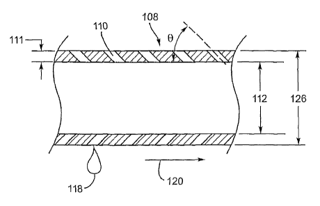
Fig. 2 illustrates a portion of the imaging window member 108 having infusion
holes
110. The infusion holes 110 are preferably smaller in diameter than the wall
thickness 111 of
the imaging window member 108. In this embodiment, the infusion holes 110
preferably have
a diameter within the range of approximately 0.040 millimeters (mm) (0.0012
inches) and 0.30
mm (0.0118 inches). The infusion holes 110 are preferably spaced apart by a
distance
approximately in the range of 0.10 mm (0.0039 inches) and 0.90 mm (0.0354
inches). The
infusion holes 110 may have a variety of shapes, e.g., the holes 110 may be
circular, elongated,
helical, and/or slots. The infusion holes 110 are preferably of a pattern to
help retain the
original bending rigidity and buckling resistance of the extrusion 106 before
the infusion holes
110 were added.
3
CA 02494714 2005-02-03
WO 2004/014233 PCT/US2003/021614
With these example configuration and measurements, when infusion liquid 118
exits the
holes 110, radial jets of liquid into the blood stream are substantially
prevented. Multiple rows
of infusion holes 110 may be utilized to deliver up to 4 milli-liters (mL) of
infusion liquid 118
per second.
Further, the infusion holes 110 are preferably angled outward toward the
proximal end of
the catheter 100 at an angle 0 , preferably approximately within the range of
15 to 60 from
the axis of the catheter 100, which causes the flow direction of the infusion
liquid 118 exiting
the infusion holes 110 to be opposite the flow direction of the blood 120.
Having the infusion
liquid 118 flow against the direction of the blood flow 120 improves the
mixing of the infusion
liquid 118 and the blood, and thus providing a more thorough dilution in a
more efficient
manner.
As shown in Fig. 1, locating the infusion holes 110 proximal to the imaging
area 122
provides two advantages: first, the infusion liquid 118 is carried distally by
the blood flow 120,
thus optimum dilution may occur around the imaging area; and second, false
data or image
artifacts may be created by the material discontinuity presented between the
infusion holes 110
and the imaging window member 108. Of course, if desired, the location of the
infusion holes
110 can be somewhere on the catheter other than proximal to the imaging area
122, such as
distal to the imaging area 122. Further, the size, shape, spacing and
configuration of the
infusion holes 110 can take various forms.
For example, the diameter of the infusion holes 110 may be tapered with a
smaller
diameter at the inner surface 112 of the imaging window member 108 and a
larger diameter at
the outer surface 126 of the imaging window member 108. Further, the infusion
holes 110 may
be tapered at an angle to further reduce radial jetting.
FIG. 3 is an illustration of a preferred embodiment of an improved imaging
catheter
assembly. The assembly 200 includes an imaging catheter 100, such as the
catheter 100 shown
in Fig. 1, having its luer fitting 102 coupled with a luer adapter 208, which
in turn, is coupled
with another luer fitting 205, which forms a high-pressure seal. The luer
adapter 208 includes a
sidearm 206, which provides a port to attach a syringe or other high-pressure
injection system
(not shown), e.g., a MedRad injector commonly found in catheterization labs.
With the
sidearm 206, infusion liquid 118 may be injected into the catheter 100,
through the lumen 109,
and out the infusion holes 110.
The luer fitting 205 is coupled with a telescope assembly 204, which includes
an inner
tube 220 sliding within an outer tube 210 and a sliding seal 230 to prevent
leakage. The
4
CA 02494714 2005-02-03
WO 2004/014233 PCT/US2003/021614
telescope assembly 204 allows an imaging core assembly 312 (shown in Fig. 4)
to slide axially
inside the imaging catheter 100.
The telescope assembly is coupled with a catheter connector assembly 202,
preferably
with epoxy to create a sealed system that can handle high pressures without
leakage.
Fig. 4 is a detailed drawing of an example embodiment of the connector
assembly 202,
which receives an imaging core assembly 312. The imaging core assembly 312
preferably
includes an optical fiber connector assembly 302, an optical fiber 304, a
gland 306, a driveshaft
310, and a distal optics assembly 314. During operation, the imaging core
assembly 312 rotates
while the remaining components of the connector assembly 202 are held
rotationally stationary.
An O-ring 308 surrounds the gland 306 creating a high pressure seal. The O-
ring 308 may be
lubricated with a high vacuum grease (not shown) to improve its sealing
capacity while
reducing rotational friction. The gland 306 is bonded to the optical fiber
connector 302 with
epoxy.
The optical fiber connector 302 is adapted to be coupled with an optical fiber
receptacle
(not shown) within a drive motor assembly (not shown) to efficiently transfer
light into the
optical fiber 304 housed within the driveshaft 310. The catheter connector
assembly 202
provides a secure attachment to the drive motor assembly (not shown), which
provides the
rotary drive to rotate the optical fiber connector 302, which in turn rotates
the driveshaft 310 of
the imaging core assembly 312.
Turning to a more detailed discussion of the mixture of the infusion liquid
118 and blood,
in the case of an imaging catheter emitting light, e.g., an OCT catheter, the
infusion liquid 118
is preferably translucent, as mentioned above. The liquid 118 should readily
mix with the
blood, and preferably should raise the refractive index of the liquid portion
of the blood, known
as the blood serum, to the refractive index of the RBCs. The RBCs typically
have a refractive
index of approximately 1.40, whereas the refractive index of blood serum is
approximately
1.33.
A clear, low viscosity liquid with an index of refraction higher than 1.33
will raise the
index of the liquid portion of blood closer to 1.40, and thus reduce the
scattering of light that
most severely attenuates the signal. One such preferable liquid is a saline
solution.
However, saline carries little oxygen and other nutrients to the heart muscle,
and thus
angina may occur as a side effect of infusing saline into the blood stream. An
alternative liquid
for infusion is DextranTM. Upon investigation, DextranTM, when mixed with
saline is a viscous
liquid, which may require additional pressure to achieve the desired infusion
rate. Another
CA 02494714 2005-02-03
WO 2004/014233 PCT/US2003/021614
alternative liquid is FluorosolTM. Other infusion liquids 118 may also be
used, such as those
that carry a similar oxygen and nutrient load to that of blood.
While the invention is susceptible to various modifications, and alternative
forms,
specific examples thereof have been shown in the drawings and are herein
described in detail.
It should be understood, however, that the invention is not to be limited to
the particular forms
or methods disclosed, but to the contrary, the invention is to cover all
modifications,
equivalents and alternatives falling within the spirit and scope of the
appended claims.
In the foregoing specification, the invention has been described with
reference to specific
embodiments thereof. It will, however, be evident that various modifications
and changes may
be made thereto without departing from the broader spirit and scope of the
invention. For
example, the reader is to understand that the specific ordering and
combination of process
actions described herein is merely illustrative, and the invention can be
performed using
different or additional process actions, or a different combination or
ordering of process
actions. For example, though the embodiment described above involves an OCT
imaging
catheter that emits light, the principles of the invention may readily
applicable to an imaging
catheter that uses a different form of energy, such as ultrasound. In other
words, a person of
skill in the art of catheter design and/or imaging may use a plurality of
infusion holes 110 on a
variety of imaging devices. As a further example, each feature of one
embodiment can be
mixed and matched with other features shown in other embodiments. Features and
processes
known to those of ordinary skill in the art of catheter design and/or imaging
may similarly be
incorporated as desired. For instance, the imaging device may include optional
balloons,
cauterization devices, cutting devices, drug delivery systems, and scopes.
Additionally and
obviously, features maybe added or subtracted as desired. Accordingly, the
invention is not to
be restricted except in light of the attached claims and their equivalents.
6