Note: Descriptions are shown in the official language in which they were submitted.
CA 02494862 2005-02-04
WO 2004/020102 PCT/SE2003/001319
1
A MEMBER FOR HOLDING A WEAR PART OF A CRUSHER
Technical Field of the Invention
The present invention relates to a holding member
for holding a horizontal wear plate in position on a
rotor for a vertical shaft impact crusher.
Background Art
Vertical shaft impact crushers (VSI-crushers) are
used in many applications for crushing hard material like
rocks, ore etc. US 3,154,259 describes a VSI-crusher
comprising a housing and a horizontal rotor located
inside the housing. Material that is to be crushed is fed
into the rotor via an opening in the top thereof. With
the aid of centrifugal force the rotating rotor ejects
the material against the wall of the housing. On impact
with the wall the material is crushed to a desired size.
The housing wall could be provided with anvils or have a
bed of retained material against which the accelerated
material is crushed.
The rotor of a VSI-crusher usually has a horizontal
upper disc and a horizontal lower disc. The upper and
lower discs are connected with a vertical rotor wall. The
upper disc has an aperture for feeding material into the
rotor. The material lands on the lower disc and is then
thrown out of the rotor via openings in the rotor wall.
The material to be crushed is often abrasive. To
extend the technical life of the upper and lower discs
they are often lined with replaceable wear plates. The
wear plates are made from an abrasion resistant material
and are replaced when they are worn down.
US 4,796,322 to Terrenzio describe wear plates made
in pairs. At each rotor opening two wear plates are put
on each of the upper and lower discs. One of the wear
plates has a recess with the intention of collecting a
CA 02494862 2005-02-04
WO 2004/020102 PCT/SE2003/001319
2
bed of material for improved wear resistance. The wear
plates interact with each other and are also held in
place by a landing ring.
US 4,896,838 to Vendelin describes wear plates made
in pairs. A first wear plate locates against a gusset
block provided at the inside of the rotor wall. A second
wear plate holds the first wear plate in place by means
of a bevel overlapping a corresponding bevel of the first
wear plate.
The wear plates described above are difficult to
replace and do not ensure a stable bed being built up
against the vertical rotor wall.
Summary of the Invention
It is an object of the present invention to provide
a holding member for holding wear plates on a rotor such
that the wear plates are easy to replace and that a
stable bed of material is provided inside the rotor.
This object is achieved with a holding member
according to the preamble and characterised in that the
holding member comprises a holding part for holding the
wear plate and a fixing means for releasably fixing the
holding member to a vertical wall segment of said rotor
such that the wear plate bears against a first side of
said wall segment.
An advantage with such a holding member is that it
is easy to replace when worn. Thus the holding member
may, if found necessary, be replaced at the same time as
the wear plate without causing extra downtime. The fact
that the holding member allows the wear plate to bear
against the first side of the wall segment decreases the
wear on said wall segment and in particular on the
horizontal rotor disc on which the wear plate rests.
Another advantage is that the wear plate bearing against
the first side of the wall segment will have a well
defined and predictable position on the rotor. Thus the
risk of the rotor becoming imbalanced is greatly reduced.
CA 02494862 2005-02-04
WO 2004/020102 PCT/SE2003/001319
3
The time required for balancing the rotor after a change
of wear plates is reduced and so is the risk of the wear
plates getting out of position during operation.
According to a preferred embodiment the holding part
comprises a bar adapted to extend through a hole in the
wall segment. The bar is simple to manufacture and
provides a stable fixing of the wear plate. Since the bar
extends through a hole in the wall segment the position
of the holding member is well defined. The wall segment
will support the bar to increase the holding force of the
holding member.
According to another preferred embodiment said
fixing means comprises a surface portion of said bar, the
surface portion being adapted to interact with the hole
in the wall segment for forming an interference fit of
the bar in the hole. The interference fit is a very
simple mechanism of holding the holding member in correct
position. It is an advantage that no fixing means need to
be placed at the first side of the wall segment. Thus the
wear plate may bear against the first side without the
risk of interference with any fixing means.
According to another preferred embodiment the fixing
means is adapted to be located at a second side of said
wall segment opposite to said first side thereof. An
advantage with this embodiment is that the fixing means
is shielded from a bed of material built up against said
first side of said wall segment. A further advantage is
that no fixing means need to be placed at the first side
of the wall segment. Thus the wear plate may bear against
the first side without the risk of interference with any
fixing means. Still more preferably said fixing means
comprises a pin and a pin hole, said pin hole being
adapted to receive said pin for fixing the holding
member. The pin and pinhole provides for a very quick
fixing of the holding member thus reducing the downtime
required for changing the wear plates. Since the fixing
means are located at the second side of the wall segment
CA 02494862 2005-02-04
WO 2004/020102 PCT/SE2003/001319
4
and thus shielded from a bed of material built up at the
first side thereof there will be little mechanical strain
on the fixing means. The pin and pin hole are robust with
regard to dust swirling around in the crusher. Thus the
risk of the holding member and in particular the fixing
means getting stuck due to clogging is reduced.
Preferably the fixing means further comprises a bracket
to be mounted on the wall segment at said second side
thereof, the pin hole being adapted to be located between
a vertical portion of said bracket and said second side
of said wall segment such that the pin may be inserted in
the pin hole between said vertical portion and said wall
segment. The bracket provides a very convenient way of
ensuring that the holding member is secured at the
desired position and cannot fall out during operation.
The bracket will also provide some mechanical protection
for the pin such that it is not damaged by rocks bouncing
back from the crusher housing wall.
According to a preferred embodiment the holding
member comprises a handle member for inserting the
holding part through said hole in the wall segment from
said second side of said wall segment. The handle member
makes mounting and dismounting of the holding member very
quick. The insertion of the holding member°from the
second side of the wall segment makes removing,
remounting and inspection of the holding member easier
since it is not necessary for a person mounting the
holding member to reach inside the rotor and since the
bed of material need not be removed.
According to another embodiment said fixing means
comprises a surface portion of said bar, the surface
portion being threaded to interact with a threaded
portion of said hole in the wall segment. A threaded
portion of the holding member interacting with a threaded
portion at the wall of the hole in the wall segment
provides a very firm releasable fixing of the holding
member. A threaded bar is a standard detail and is thus
CA 02494862 2005-02-04
WO 2004/020102 PCT/SE2003/001319
cheap. Still more preferably the bar would be threaded
only at the part thereof adapted to interact with the
thread at the wall segment. There would thus preferably
be no thread at the part of the bar intended to be
5 located inside the bed of material and thus no risk that
the bed of material would clog the~thread.
According to a preferred embodiment the holding part
is adapted to interact with a surface of said wear plate,
said surface being the surface of the wear plate that is
remote from a rotor surface to be protected by said wear
plate. With this arrangement no holes are needed in the
wear plate since the holding part of the holding member
bears against the actual surface of the wear plate. The
wear plate is thus cheaper to manufacture and the risk of
any holes in the wear plate getting clogged is avoided.
The wear plate may also slide under (or slide over if it
is an upper wear plate) the holding part of the holding
member. Thus the wear plate may slide into contact with
the wall segment and bear against the same.
According to another preferred embodiment the
holding member comprises a wedge, the wedge being adapted
to be inserted into a hole of the vertical wall segment
and to be locked therein. A wedge is a robust element
which is easy to manufacture and which provides a firm
fixing of the wear plate on the rotor.
Preferably the wedge is adapted to be inserted into
the hole from the inner side of said vertical wall
segment such that the larger end of the wedge will become
covered by a bed of material during crusher operation.
Since the larger end becomes covered by the bed of
material there is little risk that the wedge is worn down
during operation. The centrifugal force caused by the
rotation of the rotor will force the wedge towards the
periphery of the rotor and thus further into the hole,
thus ensuring a secure and tight fit of the wedge.
Preferably the wedge comprises a dismounting surface
adapted for dismounting the wedge by a stroke impacting
CA 02494862 2005-02-04
WO 2004/020102 PCT/SE2003/001319
6
the dismounting surface, the dismounting surface being
adapted to be located at the outer side of said vertical
wall segment such that the dismounting surface will
remain free of any bed of material during crusher
operation. The dismounting surface makes removal of the
wedge simple also in the case the wedge has become stuck
inside the bed material. The fact that the dismounting
surface is not covered by the bed of material increases
the accessibility and makes dismounting quick.
The wedge preferably comprises a surface adapted for
being covered by the bed of material during crusher
operation and for breaking the bed of material when a
stroke is made to the dismounting surface. The bed of
material often becomes very hard during crusher
operation. The surface adapted for being covered by the
bed of material and for breaking said bed makes removal
of the bed of material and thus also the removal of the
wedge itself and of the wear plate much easier.
These and other aspects of the invention will be
apparent from and elucidated with reference to the
embodiments described hereafter.
_Brief Description of the Drawings
The invention will hereafter be described in more
detail and with reference to the appended drawings.
Fig 1 is three-dimensional section view and shows a
rotor for a VSI-crusher
Fig 2 is a three-dimensional view and shows the
rotor of fig 1 with the upper disc removed.
Fig 3 shows the view of fig 2 as seen from above in
a two dimensional perspective.
Fig 4 is an enlarged view of a wear plate shown in
figure 3.
Fig 5 is a cross section along the line V-V of fig 4
and shows a holding pin holding the wear plate.
Fig 6 is three dimensional view of the holding pin
~hn~nn i n f is 5 .
CA 02494862 2005-02-04
WO 2004/020102 PCT/SE2003/001319
7
Fig 7 shows a part of a wall segment as seen from
the inside, i.e. in the direction of arrow VII in fig 3,
of the rotor.
Fig 8 is a cross section along the line VIII in fig
7.
Fig 9 is an enlarged view showing the wear plate of
fig 3 as seen in the direction of arrow IX in fig 4.
Fig 10 is a section view and shows a holding pin
according to a second embodiment of the invention.
Fig 11 is a cross section and shows a wedge
according to a third embodiment of the invention.
Fig 12 is a three dimensional view and shows the
wedge of fig 11 upside down and in detail.
Fig 13 is a cross section and shows the principles
of mounting and dismounting the wedge shown in fig 11 and
12.
Fig 14 is a cross section and shows a wedge
according to a fourth embodiment of the invention.
Detailed Description of Preferred Embodiments of the
r,.,~ro,-,t-; r"-,
Fig 1 shows a rotor 1 for use in a VSI-crusher. The
rotor 1 has a roof in the form of an upper disc 2 having
a top wear plate 3 and a floor in the form of a lower
disc 4. The lower disc 4 has a hub 6, which is welded to
the disc 4. The hub 6 is to be connected to a shaft (not
shown) for rotating the rotor 1 inside the housing of a
VSI-crusher.
The upper disc 2 has a central opening 8 through
which material to be crushed can be fed into the rotor 1.
The upper disc 2 is protected from wear by upper wear
plates 10 and 12. The upper disc 2 is protected from
rocks impacting the rotor 1 from above by the top wear
plate 3. As is better shown in fig 2 the lower disc 4 is
protected from wear by three lower wear plates 14, 16 and
18.
CA 02494862 2005-02-04
WO 2004/020102 PCT/SE2003/001319
8
The upper and lower discs 2, 4 are separated by and
held together by a vertical rotor wall which is separated
into three wall segments 20, 22 and 24. The gaps between
the wall segments 20, 22, 24 define outflow openings 26,
28, 30 through which material may be ejected against a
housing wall.
At each outflow opening 26, 28, 30 the respective
wall segment 20, 22, 24 is protected from wear by three
wear tips 32, 34, 36 located at the trailing edge of the
respective wall segment 20, 22, 24.
A distributor plate 38 is fastened to the centre of
the lower disc 4. The distributor plate 38 distributes
the material that is fed via the opening 8 in the upper
disc 2 and protects the lower disc 4 from wear and impact
damages caused by the material fed via the opening 8.
During operation of the rotor 1 a bed 40 of material
is built up inside the rotor 1 against each of the three
wall segments 20, 22, 24. In fig 3 only the bed 40
located adjacent to the wall segment 20 is shown. The bed
40, which consists of material that has been fed to the
rotor 1 and then has been trapped inside it, extends from
a rear support plate 42 to the wear tips 32, 34, 36. The
bed 40 protects the wall segment 20 and the wear tips 32,
34, 36 from wear and provides a proper direction to the
ejected material. The dashed arrow A describes a typical
passage of a piece of rock fed to the rotor 1 via the
central opening 8 and ejected via the outflow opening 26.
The arrow R indicates the rotational direction of the
rotor 1 during operation of the VSI-crusher.
Each wall segment 20, 22, 24 is provided with a
cavity wear plate 44, 46, 48, each consisting of three
cavity wear plate portions. The cavity wear plates 44,
46, 48 protects the rotor 1 and in particular the wear
tips 32, 34, 36 from material rebounding from the housing
wall and from ejected material and airborne fine dust
spinning around the rotor 1.
CA 02494862 2005-02-04
WO 2004/020102 PCT/SE2003/001319
9
The wall segment 20 comprises a first wall portion
20a which is substantially tangential to the disc 4 and
thus the rotor 1. A second wall portion 20b is fixed to
the first portion 20a such that an "L" with an angle of
about 130° is formed of the two portions 20a, 20b.
Fig 4 shows a tip holder 50 holding the wear tip 36
and extending along the first wall portion 20a. As can be
seen from fig 4 the wear plate 14 has a first face 52
being located adjacent to and in contact with the inner
side of the second wall portion 20b. The wear plate 14
has a second face 54 being located adjacent to and for a
part of its length in contact with inner side of the
first wall portion 20a. A third face 56 of the wear plate
is located adjacent to, but not in contact with, the
distributor plate 38 for a part of its length. A fourth
face 58 is located adjacent to the outflow opening 26.
The wear plate 14 is flat an may be made from white
iron thus being resistant to both abrasion and impact
forces. As alternative the wear plate 14 may be made by
coating a hard metal, such as tungsten carbide, or a
ceramic on a flat steel base. The flat shape is
preferable since it makes the wear plate cheap to
manufacture and easy to install. The flat shape also
promotes the stability of the bed 40 of material since no
protrusions on the surface of the wear plate disturb the
bed 40.
The wear plate 14 is kept in place at four
positions. Two holding members in the form of retractable
holding pins 60, 62 are inserted through holes in the
second wall portion 20b. A gusset 64 is located adjacent
to the fourth face 58. A shoulder 66 of the tip holder 50
holds the wear plate 14 in position at the first wall
portion 20a.
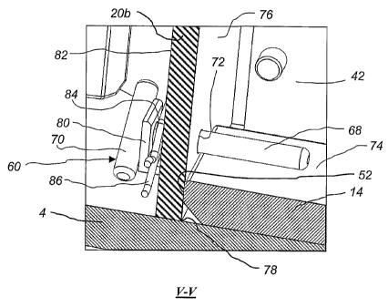
In fig 5 the holding pin 60 is shown holding the
wear plate 14 in position. The holding pin 60 has the
shape of a "T" and thus has a stem 68 and a handle member
in the form of a top part 70. The stem 68 is inserted
CA 02494862 2005-02-04
WO 2004/020102 PCT/SE2003/001319
through a hole 72 in the second wall portion 20b. At an
inner side of the wall portion 20b the stem 68 is in
contact with the upper surface 74 of the wear plate 14.
The wear plate 14 rests in direct contact with a first
5 side of the wall portion 20b said first side being the
inner wall face 76 of the second wall portion 20b. When
the rotor 1 is rotated the centrifugal forces will drive
the wear plate 14 into firm contact with the inner wall
face 76 such that there is no gap between the first face
10 52 of the wear plate 14 and the inner wall face 76. Thus
there is no risk that rock material could cause wear at
the sensitive transition 78 between the second wall
portion 20b and the disc 4. The wear plate 14 is bevelled
at the under side so that any welding joint joining the
second wall portion 20b and the lower disc 4 does not
prevent the wear plate 14 from contacting the second wall
portion 20b.
An "L"-shaped bracket 80 is welded to a second side
of said wall portion 20b, said second side being the
outer wall face 82 of the wall portion 20b and opposite
to the inner wall face 76 thereof. The bracket 80 has a
hole 84 in its vertical portion., the hole 84 being in
register with the hole 72 in the second wall portion 20b.
The holding pin 60 is inserted such that the stem 68
passes through the hole 84 of the bracket 80 and then
through the hole 72 in the second wall portion 20b. The
stem 68 bears against the upper surface 74 of the wear
plate 14. A spring dowel pin 86 is inserted through a
hole 88 in the stem 68. The spring dowel pin 86 is
located between the outer wall face 82 of the second wall
portion 20b and the vertical portion of the bracket 80
such that the holding pin 60 cannot move in any
direction.
In fig 6 the pin 60 is shown retracted and with the
spring dowel pin 86 inserted in the hole 88 in the stem
68. The stem 68 is preferably manufactured from mild
steel since it is protected from wear by the bed 40 of
CA 02494862 2005-02-04
WO 2004/020102 PCT/SE2003/001319
11
material. During normal operation of the rotor 1 the stem
68 may be worn slightly at its free end since the
extension of the bed 40 to a certain degree is
alternately reduced and expanded also during normal
operation. The stem 68 preferably has such a length that
it is entirely covered by the bed 40 of material. The
round shape of the stem 68 is easy to manufacture, fits
well to a bored hole 72 and makes the holding properties
of the stem 68 independent of any turning of the holding
pin 60. The top part 70 is shaped so as to make insertion
and withdrawal of the holding pin 60 easy. The material
of the top part 70 is preferably mild steel.
In fig 7 three tip holders 50 are shown. Each tip
holder 50 comprises a holding part 92 that holds the
respective wear tip 32, 34, 36. The wear tips 32, 34, 36
forms an unbroken line of wear tips extending from the
lower disc 4 to the upper disc 2 (the upper disc 2 being
outside the view of fig 7). Attached to the holding part
92 of each tip holder 50 is a holding plate 94. The
holding plate 94 has a threaded bar 96 which extends
through a hole 98 in the second wall portion 20b. A not
shown nut is fixed to the threaded bar 96 at the other
side of the second wall portion 20b thus securing the
respective tip holders 50 to the wall segment 20. The
vertical extension of the holding plate 94 is smaller
than that of the holding part 92. An lower shoulder 66
and an upper shoulder 100 is thus formed on the holding
plate 94. The lower shoulder 66 of the tip holder 50
holding the wear tip 32 in place holds the wear plate 14
in position. The upper shoulder (not shown in figure 7)
of the tip holder 50 holding the wear tip 36 holds an
upper wear plate in position in a similar manner.
In fig 8 the principle of the shoulder 66 is shown
.in more detail. As can be seen the wear plate 14 extends
under the shoulder 66 of the tip holder 50 such that the
second face 54 of the wear plate 14 is in direct and
close contact with the first wall portion 20a. Thus it is
CA 02494862 2005-02-04
WO 2004/020102 PCT/SE2003/001319
12
ensured that the sensitive transition 102 between the
first wall portion 20a and the lower disc 4 is protected
by the wear plate 14. The wear plate 14 is bevelled at
the under side so that any welding joint joining the
first wall portion 20a and the lower disc 4 does not
prevent the wear plate 14 from contacting the first wall
portion 20a. During operation the centrifugal force
generated by the rotation of the rotor 1 will force the
wear plate outwards such that a direct contact between
the first face 52 of the wear plate 14 and the second
wall portion 20b and between the second face 54 of the
wear plate 14 and the first wall portion 20a is ensured.
Thus the risk of wear at sensitive transitions 78, 102 is
reduced. Also the well defined location. of the wear plate
14 in relation to the wall segment 20 ensures that the
rotor 1 is kept well balanced.
In fig 9 the holding of the wear plate 14 at the
outflow opening 26 is shown in detail. The gusset 64 has
a notch 104 adjacent to the lower disc 4. The wear plate
14 has, at its fourth face 58, a lip 106. The lip 106
fits under the notch 104 such that the wear plate 14 is
held in position under the gusset 64. The gusset 64 has a
shorter height from the plate 4 than the wear plate 14 to
protect the gusset 64 from wear caused by the material
leaving the outflow opening 26.
When mounting a wear plate 14 the wear plate 14 is
first put on the lower disc 4 such that the wear plate 14
is in contact with the rear support plate 42. The wear
plate 14 is then guided against the outflow opening 26
such that the lip 106 engages the notch 104 of the gusset
64. The holding pins 60, 62 are inserted via the holes in
the second wall portion 20b and are then locked with the
help of the spring dowel pins 86. The centrifugal force
will then force the wear plate 14 into firm, direct
contact with the first and second wall portions 20a and
20b respectively. Dismounting of the wear plate 14 is
CA 02494862 2005-02-04
WO 2004/020102 PCT/SE2003/001319
13
basically performing the steps above in the reverse
order.
It will be appreciated that, although the
description above is directed to wear plates 14, 16, 18
of the lower disc 4 of the rotor 1, the principles
described above of holding wear plates in position are
applied also for the holding of the upper wear plates 10,
12 in position on the upper disc 2.
Fig 10 shows a holding pin 160 according to a second
embodiment of the invention. This embodiment differs from
the holding pin 60 described in fig 5 and 6 mainly in
that a circular stem 168 of the holding pin 160 extends
into a horizontal, circular wear plate hole 115 formed in
a first face 152 of a wear plate 114. Thus the stem 168
is well protected from wear, also during the time before
a bed 40 of material has been built up against the wall
segment 20. A handle in the form of a top part 170 is
used for inserting the stem 168 of the holding pin 160
into the wear plate hole 115 when mounting the wear plate
114 to the rotor 1. As can be seen the first face 152 of
the wear plate 114 rests in direct contact with the inner
wall face 76 of the second wall portion 20b.
Fig 11 shows a holding member in the form of a bar
shaped as a wedge 260 according to a third embodiment of
the invention. The wedge 260 holds the wear plate 14 in
position. The wedge 260 is inserted through a hole 272 in
the second wall portion 20b. At an inner side of the wall
portion 20b the wedge 260 is in contact with the upper
surface 74 of the wear plate 14. The wear plate 14 rests
in direct contact with a first side of the wall portion
20b said first side being the inner wall face 76 of the
second wall portion 20b. When the rotor 1 is rotated the
centrifugal forces will drive the wear plate 14 into firm
contact with the inner wall face 76 in a similar manner
as described above with reference to fig 5.
A spring dowel pin 286 or a ring cotter 287 is
mounted on the wedge 260 at a second side of said wall
CA 02494862 2005-02-04
WO 2004/020102 PCT/SE2003/001319
14
portion 20b, said second side being the outer wall face
82 of the wall portion 20b and opposite to the inner wall
face 76 thereof (fig 11 and fig 13 show both a spring
dowel pin 286 and a ring cotter 287, however it will be
appreciated that only one of the pin 286 and the cotter
287 is required). The spring dowel pin 286 (or the ring
cotter 287) prevents the wedge 260 from falling out of
the hole 272 in the event the wedge 260 would
accidentally become released from the hole 272.
Fig 12 shows the wedge 260 turned upside down and in
greater detail. The lower long side of the wedge 260 is a
flat side 262 intended for contacting the upper surface
74 of the wear plate 14. At the larger end 264 of the
wedge 260 a vertical mounting surface 266 is formed. At
the smaller end 268 of the wedge 260 a vertical
dismounting surface 270 is formed. The wedge 260 has
three through holes 273, 274, 276 at the smaller end 268.
The three through holes 273, 274, 276 are intended for
the mounting of a spring dowel pin 286 or a ring cotter
287 in a suitable position. The upper long side of the
wedge 260 is a bevelled surface 278 intended for
contacting the upper part of the hole 272 and to lock the
wedge 260 to the second wall portion 20b.
The mounting and dismounting of the wedge 260 will
now be described with reference to fig 13. When mounting
the wear plate 14 and the wedge 260 there is no bed 40 of
material present. The wear plate 14 is placed on the
lower disc 4 such that the first face 52 of the wear
plate 14 rests in close contact with the inner wall face
76 of the second wall portion 20b. The smaller end 268 of
the wedge 260 is guided through the hole 272 from the
inner side of the second wall portion 20b. A hammer or
similar tool is used to strike the mounting surface 266
in the direction of the arrow M. The stroke results in
that the flat side 262 and the bevelled surface 278 of
the wedge 260 locks against the upper surface 74 of the
wear plate 14 and the upper part of the hole 272
CA 02494862 2005-02-04
WO 2004/020102 PCT/SE2003/001319
respectively. Finally the spring dowel pin 286 (or the
ring cotter 287) is inserted into one of the holes 273,
274, 276 (which are better shown in fig 12) such that the
wedge 260 cannot accidentally fall out of the hole 272.
5 During operation of the crusher a bed 40 of material
will build up against the inner wall face 76 of the
second wall portion 20b and on the wear plate 14. The bed
40 will thus cover the larger end 264 of the wedge 260 as
illustrated in fig 13. Thus the wedge 260 is protected
10 from wear during operation. The rotation of the rotor 1
will cause a centrifugal force. The centrifugal force
will tend to push the wedge 260 towards the periphery of
the rotor 1 and thus further into the hole 272. The
centrifugal force in combination with the bed 40 built up
15 around the larger end 264 of the wedge 260 ensures that
there is a minimum risk that the wedge 260 would fall out
of position during crusher operation. The spring dowel
pin 286 (or the ring cotter 287) merely serves to ensure
that the wedge 260 stays in place during the maintenance
stop and at the start of the crusher.
When the wear plate 14 is to be removed the
following procedure is used. The spring dowel pin 286 (or
the ring cotter 287) is removed. A hammer or similar tool
is used to strike the dismounting surface 270 in the
direction of the arrow D. The stroke results in that the
flat side 262 and the bevelled surface 278 of the wedge
260 release from the surface 74 of the wear plate 14 and
the upper part of the hole 272 respectively.
Simultaneously the mounting surface 266 will be forced
into the bed 40 of material and break the bed 40 into
pieces. Thus the bed 40 will become easier to remove from
the rotor. Finally the wedge 260 is taken out of the hole
272 and the wear plate 14 can be removed.
Fig 14 shows a holding member in the form of a bar
shaped as a wedge 360 according to a fourth embodiment of
the invention. The wedge 360 is made of a polymer
material, preferably a rather hard polymer material such
CA 02494862 2005-02-04
WO 2004/020102 PCT/SE2003/001319
16
as polyamide plastic (often referred to as nylon), and
has a similar shape as the wedge 260 shown in Figs. 1l to
13. The wedge 360 however has no through holes and no
spring dowel pin or cotter ring is required to ensure
that the wedge 360 is kept in place. The wedge 360 is
inserted through the hole 272 in the second wall portion
20b. At an inner side of the wall portion 20b the wedge
360 is in contact with the upper surface 74 of the wear
plate 14. The wear plate 14 rests in direct contact with
the inner wall face 76 of the second wall portion 20b in
the same way as described above with reference to Fig 13.
The lower long side of the wedge 360 is a flat side
362 intended for contacting the upper surface 74 of the
wear plate 14. At the larger end 364 of the wedge 360 a
vertical mounting surface 366 is formed. At the smaller
end 368 of the wedge 360 a vertical dismounting surface
370 is formed. The upper long side of the wedge 360 is a
flat surface 378, which is similar to the surface 278
shown in Fig. 12 but is not bevelled. The flat surface
378 is intended for contacting the upper part of the hole
272 and to lock the wedge 360 to the second wall portion
20b. A support 386 is fixed to the lower disc 4 adjacent
to the outer wall face 82 of the wall portion 20b. The
support 386 supports that part of the flat side 362 of
the wedge 360 that extends out of the hole 272. Thus the
support 386 ensures that the wedge 360 is kept in proper
position by keeping the flat side 362 in a horizontal
position.
V~Ihen mounting the wear plate 14 and the wedge 360
there is no bed 40 of material present. The wear plate 14
is placed on the lower disc 4 in a similar way as
described above and a smaller end 368 of the wedge 360 is
guided through the hole 272 from the inner side of the
second wall portion 20b. A hammer or similar tool is used
to strike the mounting surface 366 in the direction of
the arrow M. The stroke results in that the flat side 362
and the surface 378 of the wedge 360 locks against the
CA 02494862 2005-02-04
WO 2004/020102 PCT/SE2003/001319
17
upper surface 74 of the wear plate 14 and the upper part
of the hole 272 respectively. Since the wedge 360 is made
of a polymer material, which is softer than the material,
such as steel, of which the wall portion 20b is made, the
stroke will cause the surface 378 to be irreversibly
deformed by the upper part of the hole 272 without
causing any damage to the hole 272. The deformation of
the surface 378 will form a press fit providing a very
secure attachment of the wedge 360 in the hole 272 and no
spring dowel pin or cotter pin is required.
During operation of the crusher a bed 40 of material
will build up against the inner wall face 76 of the
second wall portion 20b and on the wear plate 14. The bed
40 will thus cover the larger end 364 of the wedge 360
and protect it from wear in a similar way as described
above with reference to Fig 13. The deformation of the
wedge 360 caused by the stroke in combination with the
fact that the bed 40 covers the larger end 364 of the
wedge 360 minimizes the risk that the wedge 360 could
fall out of position during operation. If the wedge 360,
in spite of this, would accidentally fall out of
position, the fact that the wedge 360 is made of a
polymer material minimizes the risk that any mechanical
damage could be caused to the rotor 1 and avoids any
metal contamination of the crushed product.
The procedure used for removing the wedge 360 is similar
to the removal procedure described above with reference
to Fig. 13. The main difference is that no spring dowel
pin or cotter ring needs to be removed before striking
the dismounting surface 370 in the direction of the arrow
D with a hammer or similar tool.
It will be appreciated that numerous modifications
of the embodiments described above are possible within
the scope of the appended claims.
According to another embodiment the holding pin 60
is replaced with a bolt inserted through the second wall
portion 20b and being fixed at the outer side of the
CA 02494862 2005-02-04
WO 2004/020102 PCT/SE2003/001319
18
second wall portion 20b. This fixing could be achieved by
a nut welded to the hole at the outside of the second
wall portion 20b. Thus the nut would replace the bracket
80, the hole of the nut being in register with the hole
72 in the second wall portion 20b. The threaded part of
the bolt extends through the hole in the second wall
portion 20b such that it holds the wear plate 14 in place
at the inside of the second wall portion 20b in a similar
manner as described above regarding the stem 68. To
decrease the problem of bed material clogging the thread
of the bolt it is preferable to turn down the thread of
the bolt at the part of the bolt that is intended for
being located inside the bed. In such a case the bolt is
threaded only at the part being intended for location
inside the nut welded to the outside of the second wall
portion 20b. A further possibility is to provide the
thread inside the actual hole in the second wall portion.
In such a case no nut would be needed.
According to another embodiment the stem 68 is
shaped to have a tight fit to the hole 72 in the second
wall portion 20b. Thus no bracket or spring dowel pin is
needed. The fixing of the pin 60 is achieved by the
interference fit of the stem 68 in the hole 72.
The main purpose of the top part is to make
insertion and removal of the pin 60 easy. As alternative
to the cylindrical top part 70 shown in fig 6 the top
part may as alternative be shaped as a normal handle or
in any other shape that is convenient for easy insertion
and removal of the pin.
As alternative to the spring dowel pin 86 a split
pin or any other type of key could be used to lock the
holding pins 60, 62 in their respective positions. It is
also possible to use a locking screw to lock the holding
pin 60.
As shown above in fig 5 the stem 68 is in close
contact with the upper surface of the wear plate 14. It
is, however, also possible to let the stem 68 extend into
CA 02494862 2005-02-04
WO 2004/020102 PCT/SE2003/001319
19
a wear plate 114 through a horizontal hole 115 formed at
the first face 152 of the wear plate 114 as shown in fig
10. Still another possibility is to provide a thread on
the stem and also inside the hole in the wear plate such
that the wear plate may be screwed against the second
wall portion.
A holding pin 60 as described above may also be used
for holding the wear plate 14 in position also at the
first wall portion 20a, the holding pin 60 thus replacing
or assisting the shoulder 66 of the tip holder 50 in
holding the wear plate 14 in position at the first wall
portion 20a.