Language selection

Search

Patent 2494881 Summary

Third-party information liability

Some of the information on this Web page has been provided by external sources. The Government of Canada is not responsible for the accuracy, reliability or currency of the information supplied by external sources. Users wishing to rely upon this information should consult directly with the source of the information. Content provided by external sources is not subject to official languages, privacy and accessibility requirements.

Claims and Abstract availability

Any discrepancies in the text and image of the Claims and Abstract are due to differing posting times. Text of the Claims and Abstract are posted:

  • At the time the application is open to public inspection;
  • At the time of issue of the patent (grant).
(12) Patent Application: (11) CA 2494881
(54) English Title: FIXING DEVICE FOR A MOVABLE WALL
(54) French Title: DISPOSITIF DE FIXATION D'UNE PAROI COULISSANTE
Status: Deemed Abandoned and Beyond the Period of Reinstatement - Pending Response to Notice of Disregarded Communication
Bibliographic Data
(51) International Patent Classification (IPC):
  • E04B 02/78 (2006.01)
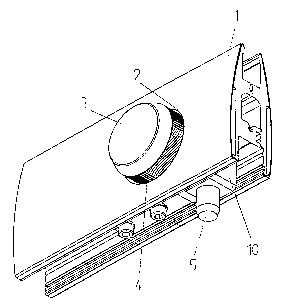
  • E05B 65/08 (2006.01)
  • E05C 01/06 (2006.01)
  • E05C 05/04 (2006.01)
(72) Inventors :
  • KLETSCHER, WILFRIED (Germany)
(73) Owners :
  • DORMA GMBH & CO. KG
(71) Applicants :
  • DORMA GMBH & CO. KG (Germany)
(74) Agent: NORTON ROSE FULBRIGHT CANADA LLP/S.E.N.C.R.L., S.R.L.
(74) Associate agent:
(45) Issued:
(86) PCT Filing Date: 2004-04-23
(87) Open to Public Inspection: 2004-11-11
Availability of licence: N/A
Dedicated to the Public: N/A
(25) Language of filing: English

Patent Cooperation Treaty (PCT): Yes
(86) PCT Filing Number: PCT/EP2004/004322
(87) International Publication Number: EP2004004322
(85) National Entry: 2005-02-03

(30) Application Priority Data:
Application No. Country/Territory Date
203 06 551.4 (Germany) 2003-04-25

Abstracts

English Abstract


The invention relates to a fixing device for a movable wall or the similar
comprising a fixing element which can be brought in the active position
thereof by means of a manual actuator. The aim of said invention is to develop
a fixing device for a movable wall or the similar ensuring a safe and reliable
functioning with the aid of simple means. For this purpose, said actuator is
embodied in the form of a rotatable button (3) whose rotation is transformable
into the longitudinal motion of the fixing device (5).


French Abstract

L'invention concerne un dispositif de fixation d'une paroi coulissante ou similaire, comportant un élément de fixation pouvant être amené en position active par l'intermédiaire d'un organe de réglage manuel. L'invention vise à mettre en oeuvre un dispositif de fixation d'une paroi coulissante ou similaire offrant un fonctionnement sûr et fiable, à l'aide de moyens simples. A cet effet, l'organe de réglage est conçu en tant que bouton tournant (3) dont la rotation peut être transformée en mouvement longitudinal de l'élément de fixation (5).

Claims

Note: Claims are shown in the official language in which they were submitted.

-6-
CLAIMS
1. Fixing device for a movable wall with a fixing element which can be
brought into its working position by an actuating member that can be actuated
manually,
characterized in that the actuating member is constructed as a turning knob
(3) whose
rotating movement can be transformed into a longitudinal movement for the
fixing
element (5).
2. Fixing device according to claim 1, characterized in that the turning knob
(3) is arranged in a recess (2) in the wall, which recess (2) surrounds the
turning knob (3)
with a slight play.
3. Fixing device according to one of the preceding claims, characterized in
that
the turning knob (3) is provided with knurling (4) on its circumferential
surface.
4. Fixing device according to one of the preceding claims, characterized in
that
the turning knob (3) is provided on its side facing the wall with an axle stub
(6) for
rotatable support of the turning knob (3) and is provided with an eccentric
pin (7)
eccentric thereto.
5. Fixing device according to one of the preceding claims, characterized in
that
the eccentric pin (7) engages in a slotted link (8) which is connected to the
fixing element
(5).

-7-
6. Fixing device according to one of the preceding claims, characterized in
that
the eccentric pin (7) is guided in a circular path (12) arranged in the wall,
the ends of the
circular path (12) serving as a stop for the rotating movement of the turning
knob (3).
7. Fixing device according to one of the preceding claims, characterized in
that
the circular path (12) is constructed as a quarter circle.
8. Fixing device according to one of the preceding claims, characterized in
that
the fixing element (5) is constructed as a catch pin.
9. Fixing device according to one of the preceding claims, characterized in
that
the fixing element (5) is guided in a carrier (10) in its displacement
direction, which
carrier (10) is held at a rail (11) arranged in the wall such that it can be
displaced and
secured.

Description

Note: Descriptions are shown in the official language in which they were submitted.


CA 02494881 2005-02-03
-1-
FIX1NG DEVICE FOR A MOVABLE WALL
Description
[0001 ] The invention is directed to a fixing device for a movable wall with a
fixing
element which can be brought into its working position by an actuating member
that can
be actuated manually.
[0002] Fixing devices of the kind mentioned above are required in walls that
are
movable manually in order to fix the walls in a determined position. Known
fixing
devices have a slide which is guided in an elongated hole provided in the wall
and which
when activated moves a fixing element connected to the slide into its working
position.
[0003] A fixing device of this kind has the disadvantage that the slide must
be received
in the elongated hole with play and that dirt and contaminants which impair
the operation
of the fixing device can therefore deposit in the elongated hole and under the
slide.
[0004] Therefore, it is the object of the present invention to provide a
fixing device for a
movable wall or the like which ensures a reliable and trouble-free operation
in a simple
manner.
[0005] This object is met by the characterizing features indicated in claim 1.
Advantageous further developments are indicated in the subclaims.
[0006] By designing the actuating member as a turning knob whose rotating
movement
can be transformed into a longitudinal movement for the fixing element, the
arrangement
of an elongated hole in the wall becomes superfluous and the slide can be
dispensed with
in its entirety. Therefore, the fixing device according to the invention is
less susceptible
to dirt and other contaminants.
[0007] According to an advantageous further development, the turning knob is
arranged
in a recess in the wall, which recess surrounds the turning knob with a slight
play. The
penetration of dirt can be effectively prevented in that the turning knob
fills the opening
provided in the wall almost completely, so that a reliable operation of the
fixing device
according to the invention can be ensured over a long period of time.

CA 02494881 2005-02-03
-2-
[0008] In order to ensure that the turning knob can be actuated with a good
grip, the
turning knob is provided with knurling on its circumferential surface in an
advantageous
further development.
[0009] According to a preferred embodiment form, the turning knob is provided
on its.
side facing the wall with an axle stub for rotatable support of the turning
knob and is
provided with an eccentric pin eccentric thereto. This enables a secure
support of the
turning knob in the wall and at the same time ensures a reliably functioning
connection to
the fixing element.
[0010] The eccentric pin advantageously engages in a slotted link which is
connected to
the fixing element. A good, reliable transformation of the rotating movement
of the
turning knob into a longitudinal movement of the fixing element is achieved
due to this
step.
[0011 ] In order to further improve the guiding of the turning knob, it is
provided
according to an advantageous further development that the eccentric pin is
guided in a
circular path arranged in the wall, the ends of the circular path serving as a
stop for the
rotating movement of the turning knob. The end positions of the rotating
movement and
therefore the two end positions of the fixing element can be reliably defined
in this way.
[0012] The circular path is preferably constructed as a quarter circle in
order that the
fixing element can move out with the smallest possible angle of rotation.
[0013] According to an advantageous further development, the fixing element is
constructed as a catch pin. The fixing element can therefore be produced in a
simple
manner.
[0014] In order to guide the fixing device according to the invention in a
reliable
manner and, above all, so as to be free from tilting, the fixing element is
guided in a
support or carrier in its displacement direction. The carrier is held at a
rail arranged in the
wall such that it can be displaced and secured. In addition, this enables a
certain
adjustment of the fixing device.
[0015] Further features and advantages of the invention are indicated in the
following
description of a preferred embodiment example.

CA 02494881 2005-02-03
-3-
[0016] Figure 1 shows a view of the fixing device according to the invention;
Figure 2 shows a cross section through the fixing device according to the
invention;
Figure 3 shows a partial section through the fixing device according to the
invention; and
Figure 4 shows another view of the fixing device according to the invention.
[0017] Figures 1 to 4 show a fixing device according to the invention which is
arranged
at a wall that is preferably manually movable. The wall (not shown) passes
into a profile
1 in its lower area. The profile 1 which comprises two half profile shells in
the present
embodiment example is provided with slightly curved outer sides (see Figure
2).
[0018] A circular recess 2 in which a turning knob 3 is supported is provided
in the
profile 1. The recess 2 encloses the turning knob 3 with a slight play so that
dirt or dust
can be prevented to a great extent from penetrating into the gap between the
recess 2 and
the turning knob 3. The turning knob 3 is provided on its outer circumference
with
knurling 4 to enable the turning knob 3 to be actuated in a reliable fashion.
[0019] The turning knob 3 is in a working connection with a fixing element 5
constructed as a catch pin so that the fixing element S can be moved out and
in by
actuating the turning knob 3.
[0020] The turning knob 3 is provided on its inner side with a centric axle
stub 6
enabling a rotatable support of the turning knob 3 in the profile 1. An
eccentric pin 7 is
provided in the vicinity of the outer edge of the turning knob 3 eccentric to
the axle stub
6. The turning knob 3 with the axle stub 6 and eccentric pin 7 can be produced
in one
piece, e.g., by means of injection molding.
[0021 ] The eccentric pin 7 engages in a slotted link 8 which receives the
eccentric pin 7
in an elongated hole 9. The slotted link 8 itself is connected to the fixing
element 5, for
example, by means of a screw connection.

CA 02494881 2005-02-03
-4-
[0022] The fixing element 5 is guided in its displacing direction in a carrier
10 which is
held in a rail 11 provided in the profile 1 so that it can be displaced and
secured. Further,
a circular path 12 which is constructed as a quarter circle and through which
the eccentric
pin 7 extends is provided in the profile 1. The ends of the circular path 12
serve as a stop
and define the rotating movement of the turning knob 3 and, therefore, the
displacement
path of the fixing element 5.
[0023] When the turning knob 3 is turned, the eccentric pin 7 moves in the
elongated
hole 9 of the slotted link 8 and accordingly moves the fixing element 5
downward or
upward depending on the rotating direction. In this way, the rotating movement
of the
turning knob 3 is transformed into a longitudinal movement of the fixing
element 5.

CA 02494881 2005-02-03
-5-
[0024]Reference Numbers
1 profile
2 recess
3 turning knob
4 knurling
fixing element
6 axle stub
7 eccentric pin
8 slotted link
9 elongated hole
carrier
11 rail
12 circular path

Representative Drawing
A single figure which represents the drawing illustrating the invention.
Administrative Status

2024-08-01:As part of the Next Generation Patents (NGP) transition, the Canadian Patents Database (CPD) now contains a more detailed Event History, which replicates the Event Log of our new back-office solution.

Please note that "Inactive:" events refers to events no longer in use in our new back-office solution.

For a clearer understanding of the status of the application/patent presented on this page, the site Disclaimer , as well as the definitions for Patent , Event History , Maintenance Fee  and Payment History  should be consulted.

Event History

Description Date
Application Not Reinstated by Deadline 2008-04-23
Time Limit for Reversal Expired 2008-04-23
Deemed Abandoned - Failure to Respond to Maintenance Fee Notice 2007-04-23
Inactive: IPC from MCD 2006-03-12
Inactive: Cover page published 2005-04-12
Letter Sent 2005-04-08
Inactive: Notice - National entry - No RFE 2005-04-08
Application Received - PCT 2005-03-01
National Entry Requirements Determined Compliant 2005-02-03
Application Published (Open to Public Inspection) 2004-11-11

Abandonment History

Abandonment Date Reason Reinstatement Date
2007-04-23

Maintenance Fee

The last payment was received on 2006-03-23

Note : If the full payment has not been received on or before the date indicated, a further fee may be required which may be one of the following

  • the reinstatement fee;
  • the late payment fee; or
  • additional fee to reverse deemed expiry.

Patent fees are adjusted on the 1st of January every year. The amounts above are the current amounts if received by December 31 of the current year.
Please refer to the CIPO Patent Fees web page to see all current fee amounts.

Fee History

Fee Type Anniversary Year Due Date Paid Date
Registration of a document 2005-02-03
Basic national fee - standard 2005-02-03
MF (application, 2nd anniv.) - standard 02 2006-04-24 2006-03-23
Owners on Record

Note: Records showing the ownership history in alphabetical order.

Current Owners on Record
DORMA GMBH & CO. KG
Past Owners on Record
WILFRIED KLETSCHER
Past Owners that do not appear in the "Owners on Record" listing will appear in other documentation within the application.
Documents

To view selected files, please enter reCAPTCHA code :


To view images, click a link in the Document Description column. To download the documents, select one or more checkboxes in the first column and then click the "Download Selected in PDF format (Zip Archive)" or the "Download Selected as Single PDF" button.

List of published and non-published patent-specific documents on the CPD .

If you have any difficulty accessing content, you can call the Client Service Centre at 1-866-997-1936 or send them an e-mail at CIPO Client Service Centre.


Document
Description 
Date
(yyyy-mm-dd) 
Number of pages   Size of Image (KB) 
Drawings 2005-02-02 1 36
Description 2005-02-02 5 162
Abstract 2005-02-02 2 85
Claims 2005-02-02 2 45
Representative drawing 2005-02-02 1 15
Notice of National Entry 2005-04-07 1 193
Courtesy - Certificate of registration (related document(s)) 2005-04-07 1 105
Reminder of maintenance fee due 2005-12-27 1 110
Courtesy - Abandonment Letter (Maintenance Fee) 2007-06-17 1 176
PCT 2005-02-02 3 88