Sélection de la langue

Search

Sommaire du brevet 2494881 

Énoncé de désistement de responsabilité concernant l'information provenant de tiers

Une partie des informations de ce site Web a été fournie par des sources externes. Le gouvernement du Canada n'assume aucune responsabilité concernant la précision, l'actualité ou la fiabilité des informations fournies par les sources externes. Les utilisateurs qui désirent employer cette information devraient consulter directement la source des informations. Le contenu fourni par les sources externes n'est pas assujetti aux exigences sur les langues officielles, la protection des renseignements personnels et l'accessibilité.

Disponibilité de l'Abrégé et des Revendications

L'apparition de différences dans le texte et l'image des Revendications et de l'Abrégé dépend du moment auquel le document est publié. Les textes des Revendications et de l'Abrégé sont affichés :

  • lorsque la demande peut être examinée par le public;
  • lorsque le brevet est émis (délivrance).
(12) Demande de brevet: (11) CA 2494881
(54) Titre français: DISPOSITIF DE FIXATION D'UNE PAROI COULISSANTE
(54) Titre anglais: FIXING DEVICE FOR A MOVABLE WALL
Statut: Réputée abandonnée et au-delà du délai pour le rétablissement - en attente de la réponse à l’avis de communication rejetée
Données bibliographiques
(51) Classification internationale des brevets (CIB):
  • E04B 02/78 (2006.01)
  • E05B 65/08 (2006.01)
  • E05C 01/06 (2006.01)
  • E05C 05/04 (2006.01)
(72) Inventeurs :
  • KLETSCHER, WILFRIED (Allemagne)
(73) Titulaires :
  • DORMA GMBH & CO. KG
(71) Demandeurs :
  • DORMA GMBH & CO. KG (Allemagne)
(74) Agent: NORTON ROSE FULBRIGHT CANADA LLP/S.E.N.C.R.L., S.R.L.
(74) Co-agent:
(45) Délivré:
(86) Date de dépôt PCT: 2004-04-23
(87) Mise à la disponibilité du public: 2004-11-11
Licence disponible: S.O.
Cédé au domaine public: S.O.
(25) Langue des documents déposés: Anglais

Traité de coopération en matière de brevets (PCT): Oui
(86) Numéro de la demande PCT: PCT/EP2004/004322
(87) Numéro de publication internationale PCT: EP2004004322
(85) Entrée nationale: 2005-02-03

(30) Données de priorité de la demande:
Numéro de la demande Pays / territoire Date
203 06 551.4 (Allemagne) 2003-04-25

Abrégés

Abrégé français

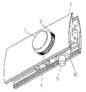
L'invention concerne un dispositif de fixation d'une paroi coulissante ou similaire, comportant un élément de fixation pouvant être amené en position active par l'intermédiaire d'un organe de réglage manuel. L'invention vise à mettre en oeuvre un dispositif de fixation d'une paroi coulissante ou similaire offrant un fonctionnement sûr et fiable, à l'aide de moyens simples. A cet effet, l'organe de réglage est conçu en tant que bouton tournant (3) dont la rotation peut être transformée en mouvement longitudinal de l'élément de fixation (5).


Abrégé anglais


The invention relates to a fixing device for a movable wall or the similar
comprising a fixing element which can be brought in the active position
thereof by means of a manual actuator. The aim of said invention is to develop
a fixing device for a movable wall or the similar ensuring a safe and reliable
functioning with the aid of simple means. For this purpose, said actuator is
embodied in the form of a rotatable button (3) whose rotation is transformable
into the longitudinal motion of the fixing device (5).

Revendications

Note : Les revendications sont présentées dans la langue officielle dans laquelle elles ont été soumises.


-6-
CLAIMS
1. Fixing device for a movable wall with a fixing element which can be
brought into its working position by an actuating member that can be actuated
manually,
characterized in that the actuating member is constructed as a turning knob
(3) whose
rotating movement can be transformed into a longitudinal movement for the
fixing
element (5).
2. Fixing device according to claim 1, characterized in that the turning knob
(3) is arranged in a recess (2) in the wall, which recess (2) surrounds the
turning knob (3)
with a slight play.
3. Fixing device according to one of the preceding claims, characterized in
that
the turning knob (3) is provided with knurling (4) on its circumferential
surface.
4. Fixing device according to one of the preceding claims, characterized in
that
the turning knob (3) is provided on its side facing the wall with an axle stub
(6) for
rotatable support of the turning knob (3) and is provided with an eccentric
pin (7)
eccentric thereto.
5. Fixing device according to one of the preceding claims, characterized in
that
the eccentric pin (7) engages in a slotted link (8) which is connected to the
fixing element
(5).

-7-
6. Fixing device according to one of the preceding claims, characterized in
that
the eccentric pin (7) is guided in a circular path (12) arranged in the wall,
the ends of the
circular path (12) serving as a stop for the rotating movement of the turning
knob (3).
7. Fixing device according to one of the preceding claims, characterized in
that
the circular path (12) is constructed as a quarter circle.
8. Fixing device according to one of the preceding claims, characterized in
that
the fixing element (5) is constructed as a catch pin.
9. Fixing device according to one of the preceding claims, characterized in
that
the fixing element (5) is guided in a carrier (10) in its displacement
direction, which
carrier (10) is held at a rail (11) arranged in the wall such that it can be
displaced and
secured.

Description

Note : Les descriptions sont présentées dans la langue officielle dans laquelle elles ont été soumises.


CA 02494881 2005-02-03
-1-
FIX1NG DEVICE FOR A MOVABLE WALL
Description
[0001 ] The invention is directed to a fixing device for a movable wall with a
fixing
element which can be brought into its working position by an actuating member
that can
be actuated manually.
[0002] Fixing devices of the kind mentioned above are required in walls that
are
movable manually in order to fix the walls in a determined position. Known
fixing
devices have a slide which is guided in an elongated hole provided in the wall
and which
when activated moves a fixing element connected to the slide into its working
position.
[0003] A fixing device of this kind has the disadvantage that the slide must
be received
in the elongated hole with play and that dirt and contaminants which impair
the operation
of the fixing device can therefore deposit in the elongated hole and under the
slide.
[0004] Therefore, it is the object of the present invention to provide a
fixing device for a
movable wall or the like which ensures a reliable and trouble-free operation
in a simple
manner.
[0005] This object is met by the characterizing features indicated in claim 1.
Advantageous further developments are indicated in the subclaims.
[0006] By designing the actuating member as a turning knob whose rotating
movement
can be transformed into a longitudinal movement for the fixing element, the
arrangement
of an elongated hole in the wall becomes superfluous and the slide can be
dispensed with
in its entirety. Therefore, the fixing device according to the invention is
less susceptible
to dirt and other contaminants.
[0007] According to an advantageous further development, the turning knob is
arranged
in a recess in the wall, which recess surrounds the turning knob with a slight
play. The
penetration of dirt can be effectively prevented in that the turning knob
fills the opening
provided in the wall almost completely, so that a reliable operation of the
fixing device
according to the invention can be ensured over a long period of time.

CA 02494881 2005-02-03
-2-
[0008] In order to ensure that the turning knob can be actuated with a good
grip, the
turning knob is provided with knurling on its circumferential surface in an
advantageous
further development.
[0009] According to a preferred embodiment form, the turning knob is provided
on its.
side facing the wall with an axle stub for rotatable support of the turning
knob and is
provided with an eccentric pin eccentric thereto. This enables a secure
support of the
turning knob in the wall and at the same time ensures a reliably functioning
connection to
the fixing element.
[0010] The eccentric pin advantageously engages in a slotted link which is
connected to
the fixing element. A good, reliable transformation of the rotating movement
of the
turning knob into a longitudinal movement of the fixing element is achieved
due to this
step.
[0011 ] In order to further improve the guiding of the turning knob, it is
provided
according to an advantageous further development that the eccentric pin is
guided in a
circular path arranged in the wall, the ends of the circular path serving as a
stop for the
rotating movement of the turning knob. The end positions of the rotating
movement and
therefore the two end positions of the fixing element can be reliably defined
in this way.
[0012] The circular path is preferably constructed as a quarter circle in
order that the
fixing element can move out with the smallest possible angle of rotation.
[0013] According to an advantageous further development, the fixing element is
constructed as a catch pin. The fixing element can therefore be produced in a
simple
manner.
[0014] In order to guide the fixing device according to the invention in a
reliable
manner and, above all, so as to be free from tilting, the fixing element is
guided in a
support or carrier in its displacement direction. The carrier is held at a
rail arranged in the
wall such that it can be displaced and secured. In addition, this enables a
certain
adjustment of the fixing device.
[0015] Further features and advantages of the invention are indicated in the
following
description of a preferred embodiment example.

CA 02494881 2005-02-03
-3-
[0016] Figure 1 shows a view of the fixing device according to the invention;
Figure 2 shows a cross section through the fixing device according to the
invention;
Figure 3 shows a partial section through the fixing device according to the
invention; and
Figure 4 shows another view of the fixing device according to the invention.
[0017] Figures 1 to 4 show a fixing device according to the invention which is
arranged
at a wall that is preferably manually movable. The wall (not shown) passes
into a profile
1 in its lower area. The profile 1 which comprises two half profile shells in
the present
embodiment example is provided with slightly curved outer sides (see Figure
2).
[0018] A circular recess 2 in which a turning knob 3 is supported is provided
in the
profile 1. The recess 2 encloses the turning knob 3 with a slight play so that
dirt or dust
can be prevented to a great extent from penetrating into the gap between the
recess 2 and
the turning knob 3. The turning knob 3 is provided on its outer circumference
with
knurling 4 to enable the turning knob 3 to be actuated in a reliable fashion.
[0019] The turning knob 3 is in a working connection with a fixing element 5
constructed as a catch pin so that the fixing element S can be moved out and
in by
actuating the turning knob 3.
[0020] The turning knob 3 is provided on its inner side with a centric axle
stub 6
enabling a rotatable support of the turning knob 3 in the profile 1. An
eccentric pin 7 is
provided in the vicinity of the outer edge of the turning knob 3 eccentric to
the axle stub
6. The turning knob 3 with the axle stub 6 and eccentric pin 7 can be produced
in one
piece, e.g., by means of injection molding.
[0021 ] The eccentric pin 7 engages in a slotted link 8 which receives the
eccentric pin 7
in an elongated hole 9. The slotted link 8 itself is connected to the fixing
element 5, for
example, by means of a screw connection.

CA 02494881 2005-02-03
-4-
[0022] The fixing element 5 is guided in its displacing direction in a carrier
10 which is
held in a rail 11 provided in the profile 1 so that it can be displaced and
secured. Further,
a circular path 12 which is constructed as a quarter circle and through which
the eccentric
pin 7 extends is provided in the profile 1. The ends of the circular path 12
serve as a stop
and define the rotating movement of the turning knob 3 and, therefore, the
displacement
path of the fixing element 5.
[0023] When the turning knob 3 is turned, the eccentric pin 7 moves in the
elongated
hole 9 of the slotted link 8 and accordingly moves the fixing element 5
downward or
upward depending on the rotating direction. In this way, the rotating movement
of the
turning knob 3 is transformed into a longitudinal movement of the fixing
element 5.

CA 02494881 2005-02-03
-5-
[0024]Reference Numbers
1 profile
2 recess
3 turning knob
4 knurling
fixing element
6 axle stub
7 eccentric pin
8 slotted link
9 elongated hole
carrier
11 rail
12 circular path

Dessin représentatif
Une figure unique qui représente un dessin illustrant l'invention.
États administratifs

2024-08-01 : Dans le cadre de la transition vers les Brevets de nouvelle génération (BNG), la base de données sur les brevets canadiens (BDBC) contient désormais un Historique d'événement plus détaillé, qui reproduit le Journal des événements de notre nouvelle solution interne.

Veuillez noter que les événements débutant par « Inactive : » se réfèrent à des événements qui ne sont plus utilisés dans notre nouvelle solution interne.

Pour une meilleure compréhension de l'état de la demande ou brevet qui figure sur cette page, la rubrique Mise en garde , et les descriptions de Brevet , Historique d'événement , Taxes périodiques et Historique des paiements devraient être consultées.

Historique d'événement

Description Date
Demande non rétablie avant l'échéance 2008-04-23
Le délai pour l'annulation est expiré 2008-04-23
Réputée abandonnée - omission de répondre à un avis sur les taxes pour le maintien en état 2007-04-23
Inactive : CIB de MCD 2006-03-12
Inactive : Page couverture publiée 2005-04-12
Lettre envoyée 2005-04-08
Inactive : Notice - Entrée phase nat. - Pas de RE 2005-04-08
Demande reçue - PCT 2005-03-01
Exigences pour l'entrée dans la phase nationale - jugée conforme 2005-02-03
Demande publiée (accessible au public) 2004-11-11

Historique d'abandonnement

Date d'abandonnement Raison Date de rétablissement
2007-04-23

Taxes périodiques

Le dernier paiement a été reçu le 2006-03-23

Avis : Si le paiement en totalité n'a pas été reçu au plus tard à la date indiquée, une taxe supplémentaire peut être imposée, soit une des taxes suivantes :

  • taxe de rétablissement ;
  • taxe pour paiement en souffrance ; ou
  • taxe additionnelle pour le renversement d'une péremption réputée.

Les taxes sur les brevets sont ajustées au 1er janvier de chaque année. Les montants ci-dessus sont les montants actuels s'ils sont reçus au plus tard le 31 décembre de l'année en cours.
Veuillez vous référer à la page web des taxes sur les brevets de l'OPIC pour voir tous les montants actuels des taxes.

Historique des taxes

Type de taxes Anniversaire Échéance Date payée
Enregistrement d'un document 2005-02-03
Taxe nationale de base - générale 2005-02-03
TM (demande, 2e anniv.) - générale 02 2006-04-24 2006-03-23
Titulaires au dossier

Les titulaires actuels et antérieures au dossier sont affichés en ordre alphabétique.

Titulaires actuels au dossier
DORMA GMBH & CO. KG
Titulaires antérieures au dossier
WILFRIED KLETSCHER
Les propriétaires antérieurs qui ne figurent pas dans la liste des « Propriétaires au dossier » apparaîtront dans d'autres documents au dossier.
Documents

Pour visionner les fichiers sélectionnés, entrer le code reCAPTCHA :


Pour visualiser une image, cliquer sur un lien dans la colonne description du document. Pour télécharger l'image (les images), cliquer l'une ou plusieurs cases à cocher dans la première colonne et ensuite cliquer sur le bouton "Télécharger sélection en format PDF (archive Zip)" ou le bouton "Télécharger sélection (en un fichier PDF fusionné)".

Liste des documents de brevet publiés et non publiés sur la BDBC .

Si vous avez des difficultés à accéder au contenu, veuillez communiquer avec le Centre de services à la clientèle au 1-866-997-1936, ou envoyer un courriel au Centre de service à la clientèle de l'OPIC.


Description du
Document 
Date
(aaaa-mm-jj) 
Nombre de pages   Taille de l'image (Ko) 
Dessins 2005-02-02 1 36
Description 2005-02-02 5 162
Abrégé 2005-02-02 2 85
Revendications 2005-02-02 2 45
Dessin représentatif 2005-02-02 1 15
Avis d'entree dans la phase nationale 2005-04-07 1 193
Courtoisie - Certificat d'enregistrement (document(s) connexe(s)) 2005-04-07 1 105
Rappel de taxe de maintien due 2005-12-27 1 110
Courtoisie - Lettre d'abandon (taxe de maintien en état) 2007-06-17 1 176
PCT 2005-02-02 3 88