Note: Descriptions are shown in the official language in which they were submitted.
CA 02495126 2005-O1-27
- 1 -
LOAD SUPPORT HARNESS FOR PERSON
TECHNICAL FIELD
The present invention relates to a load support
harness which is securable about a wearer person and which
is comprised of a rigid load attaching belt which is
interconnected by rigid vertical supports to a hip belt and
configured whereby to transfer a load secured thereto to the
hip belt in a substantially balanced manner to maintain
to proper equilibrium of the load about a wearer person's hip
area.
BACKGROUND ART
It is important to provide proper ergonomic
designs when developing products to be used by working
individuals who are required to support tools or other
devices to effectuate tasks on a daily basis. Usually such
tools or devices are attached to hip belts specifically
designed to carry such tools or devices, for example, as is
2o the case with carpenters, electricians, police officers,
military personnel, and the like numerous other people. It
has been found that because the articles that are attached
to hip belts vary in weight and are not properly distributed
about the belt to balance the weight, they often result in
the wearer developing physical pain in the lower and upper
back and the neck and shoulder areas. Such loads impose
important physical constraint in generating fatigue,
insufficient rest, bad working postures, etc. They also
impose other problems such as subjecting the wearer person
3o to excessive cold or heat or humidity due to the fact that
these belts place a constraint on the items of apparel that
can be worn with them.
In an attempt to resolve the above problems, load
bearing vests or belts or harnesses have been developed such
as disclosed, for example, in U.S. Patents 4,106,121,
5,351,340 and 6,766,532. However, such have been found
CA 02495126 2005-O1-27
- 2 -
inadequate and they often affect the mobility of the wearer
person. They are also uncomfortable to wear. To improve
the comfort, such belts are usually provided with cushions
secured thereto but this does not solve the problem of
having an unbalanced load disposed about a wearer's hip
area. It is also known to support heavy loads on the back
by providing a harness as, for example, described in U.S.
Patent 6,401,715. With that harness, the load distribution
is primarily over the shoulders of a wearer person and this
to often leads t:o back problems as previously described. Also,
in that Patent the heavy load is a breathing tank and is
weight is greatly reduced when the person enters a body of
water. These devices also restrict the mobility of the
wearer person, in other words, the wearer person has
i5 difficulty in bending its body when wearing the harness.
These devices also lead to fatigue and spinal problems.
Certain of these devices are also difficult to adapt to a
wearer person and there is the need to provide a harness
which can be: rapidly connected about a person's body and
2o adjusted for comfort. There is also a need to provide a
harness which is aesthetically pleasing to the eye and which
may be integrated in various articles of apparel depending
on its intended use.
With the known supports of the prior art, and as
2s above described, the weight is carried primarily by the
shoulders or the hips of the wearer person. The application
of a load to the shoulders compresses the superior
trapezoidal muscles which often result in compression of the
spinal discs. According to biomechanical fundamentals, one
3o needs to app:Ly a load on a stable structure of the skeleton
and the buttock must serve as the support base. Although
conventional hip belts are secured thereabove, they are not
adequate as they do not apply the entire load onto the
buttock and the load is not balanced.
35 There is also a need to provide a load support
harness which can be adapted to articles of apparel whereby
CA 02495126 2005-O1-27
- 3 -
the human body can function adequately. If integrated into
a vest, such vest can interfere with the thermal temperature
regulating mechanism of a human body, as mentioned above.
In the winter, the objective is to maintain body heat.
s Accordingly, it is necessary to provide a load support
harness which can be integrated into a thermal insulating
article of apparel and which can be adjusted to adapt it to
various body sizes. In summer months, on the other hand,
the body must evacuate heat. In other words, the body must
to transfer heat to ambient air which is in contact with the
skin. Therefore, the load support harness and apparel must
not interfere with this process. The harness must permit
the evaporation of sweat which provides proper heat transfer
between the body and the ambient air.
is
SUMMARY OF INVENTION
It is a feature of the present invention to
provide a novel load support harness which substantially
overcomes all of the above-mentioned disadvantages of the
2o prior art.
According to the above feature, from a broad
aspect, the present invention provides a load support
harness comprising a rigid load attaching belt for
supporting a load secured thereto. A hip belt of flexible
2s material is adapted to be adjustably secured about the hip
of a wearer person. The hip belt is secured to the rigid
load attaching belt and supported therebelow by rigid
vertical supports. The rigid vertical supports are disposed
for transmitting the load secured to the rigid load
3o attaching belt to the hip belt in a substantially balanced
manner to maintain proper equilibrium of the load about a
wearer person's hip area.
CA 02495126 2005-O1-27
- 4 -
BRIEF DESCRIPTION OF DRAWINGS
A preferred embodiment of the present invention
will now be described with reference to the accompanying
drawings in which:
s FIG. lA is a frontal view of a first embodiment of
the load support harness, partly fragmented;
FIG. 1B i.s a rear view of the load support harness
of Figure lA;
FIG. 2 is a front view showing the construction of
to a vest incorporating the load support harness of the present
invention as illustrated by Figures lA and 1B;
FIG. 3 is the rear view of the vest of Figure 2;
FIG. 4 is a perspective view showing the
adjustability of the rigid load attaching belt;
15 FIG. 5A is a rear view showing a further
embodiment of the :rear vertical support herein comprised of
a rigid molded shell;
FIG. 5B is a frontal view of the embodiment of
Figure 5A;
2o FIG. 6 is a perspective view showing a further
embodiment of the rigid load attaching belt which is herein
molded of a single rigid formable material;
FIG. 7 is a front view of Figure 6;
FIG. 8 is a rear view of Figure 6; and
25 FIC~. 9 is a section view of a belt section of the
embodiment of Figure 6.
DESCRIPTION OF PREFERRED EMBODIMENTS
Referring now to the drawings and more
3o particularly to Figures lA and 1B, there is shown generally
at 10 an embodiment of a load support harness constructed in
accordance with the present invention. Essentially, the
load support harness 10 is comprised of a rigid load
attaching belt 11 Formed of rigid flexible plastic material
35 or other suitable material and capable of being bent to be
secured about the body of a person by interconnecting
CA 02495126 2005-O1-27
buckles 12 and 12' secured to respective free ends 13 and
13' of the rigid load attaching belt 11. A hip belt 14 of
suitable flexible material such as nylon strapping, etc. is
also provided with a buckle 15 and adapted to be adjustably
s secured about the hip of a wearer person. The hip belt 14
is secured to the rigid load attaching belt 11 and
positioned spaced below by rigid vertical supports 16. As
shown in Figure lA, which is a front view of the load
support harness, there are frontal vertical supports 16' and
to as shown in Figure 1B, which is a rear view of the load
support harness 10. There are also rear vertical supports
16". These vertical supports 16 are constructed of rigid
plastic material which is also flexible and may be formed of
the same material as the rigid load attaching belt 11.
15 The vertical supports 16 are disposed at strategic
locations whereby to transmit a load which is secured to the
rigid load attaching belt 11 directly onto the hip belt 14
and in a substantially balanced manner whereby to maintain
proper equilibrium or balance of the load about a wearer
2o person's hip area and more specifically on top of the filial
crest of the hip region. These supports 16' and 16"
constitute frontal and rear support means and these can have
different shapes, as will be described later.
As shown in Figure 1B, the rear support means is
25 comprised of two rigid lombard vertical struts 16" , each of
which is disposed on a respective side of the spinal cord of
the wearer person and herein identified by the central
vertical axis 17. These struts 16" are immovably secured at
their lower ends 18 and 18' to the hip belt 14 in connecting
3o pockets 19 which receive the lower ends therein to permit
attachment thereto by stitches 20. The upper end portions
21 of the struts 16" are retained captive in further pockets
22 but are permitted to be displaced axially therein in
opposed directions as indicated by arrow 23. This is to
35 provide unconstrained bending of the wearer person's body
when bending forwardly or rearwardly and even sideways. As
CA 02495126 2005-O1-27
- 6 -
also hereinshown, these lombard vertical struts 16" have an
upper back restraining portion 24 which project above the
rigid load attaching belt 11 and intended to extend over the
large muscles in the back of the wearer person on opposed
sides of the spinal. cord. This permits the wearer person to
assume a more erect body posture and consequently provide
more comfort to the wearer. Although not shown herein, the
rigid load attaching belt 11 is retained captive in fabric
material as well as are the rigid vertical support struts
l0 16" thereby providing for limited displacement of the struts
in the pockets 22 and 22' and connection with the belt 11
whereby the struts 16" provide for load transfer between the
rigid load attaching belt 11 and the hip belt 14.
As shown in Figure lA, the frontal vertical struts
i5 16' are rigidly connected at a lower end in pockets 25 and
25' and in a similar manner as described with respect to
Figure 1B. The upper end of the frontal vertical strut 16'
is received in respective pockets 26 and 26' and may be
rigidly interconnected thereto by snap connectors 27 and
20 27'. Accordingly, the upper part of the vertical strut 16'
can be quickly disconnected from the load support harness 11
in order to ;permit attachment of load support members, such
as the pouch 28 as shown in Figure 6, wherein the securing
loop 29 then-eof may be slid over either end of the load
25 attaching belt 11. These snap connectors 27 and 27' also
provide an articulated connection to permit side
displacement when adjusting the rigid load attaching belt 11
about a wearer's body.
With reference now to Figure 4, there is shown
3o another embodiment of the rigid load attaching belt 11 and
as hereinshown this belt 11' is adjustable in length whereby
to adapt to the various size bodies of the wearer person.
The belt 11' is constructed of two curved belt sections 35
and 35' which are interconnected by an adjustable strap 36.
35 A strap and buckle 37 is connected to a free end 38' of the
belt section 35'. An adjustable strap 36 is also connected
CA 02495126 2005-O1-27
-
at a secured end 39 to the other section 35 of the
adjustable belt. Accordingly, by adjusting the free strap
end 40 of the strap 36 with the buckle 37, the belt can be
adjusted lengthwise.
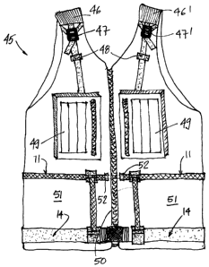
With reference now to Figures 2 and 3, there is
shown the load support harness 10 of Figures lA and 1B
integrated into a vest 45. The vest 45 is provided with
adjustable shoulder straps 46 and 46' which are adjustable
by buckles 47 and 47', respectively. Velcro connectors, as
io is well known in the art, can also provide for this
adjustment. These shoulder straps may also contain
cushioning material. Velcro tabs 48 are secured to the vest
and provide for the attachment of various articles such as
cellular phone pouches, walkie-talkies, etc. Pockets 49 may
i5 also be provided and their openings secured by Velcro or
other type of securement means permitting access therein.
As hereinshown, the vest is secured in the frontal portion
thereof by a zipper 50 but other attachment means can be
provided such as Velcro, snaps, etc. The frontal portions
20 51 of the vESt are also provided with through slots 52 on
opposed sides of the zipper whereby to permit the passage of
the buckles 12 and 12' secured to the free ends of the rigid
load attachment belt 11 whereby these buckles can be
attached behind the vest. Accordingly, the zipper fastener
25 50 is closeable thereover. The hip belt 14 needs to be
secured snug about the hip of the wearer person.
As shown in Figure 3, the back of the vest 45 is
provided with vertical channels 55 to receive the Lombard
vertical struts 16" therein and a transverse horizontal
3o channel 56 to receive the rigid load attaching belt 11
therethrough. These channels provide for movement of the
belt therein, particularly when the belt 11 is an adjustable
belt as illustrated in Figure 4. A different fabric
material can be sewn in the central spinal area 57 for
35 comfort. The vest is also provided with loops 58 to
restrain the hip belt 14 in the hip region of the wearer.
CA 02495126 2005-O1-27
_ g _
As shown in the rear view of Figure 3, it is
conceivable that a further rigid load attaching belt 11'
could be secured above the belt 11 and extending
substantially parallel thereto. Such a belt would also be
in communication with the upper region 24 of the rear
vertical struts 16" and connected thereto whereby to also
transfer the load down to the hip belt 14. It may be
convenient to have two belts 11 and 11' depending on the
type of equipment to be carried by the intended user person.
io Although not shown but obvious to a person skilled in the
art, various other attachments can be integrally formed with
the vest 45.
Referring now to Figures 5A and 5B, there is shown
the load support harness 10 of the present invention
integrated with a different type of article of apparel,
herein a shirt or a sweater 60 and a pair of pants 61 which
may be of conventional design. These pants 61 could also be
modified whereby they are provided with loops of sufficient
size to receive the hip belt 14 therethrough. Figure 5A is
2o a rear portion of the harness wherein it illustrates the
securement thereof to the shirt 60 and as hereinshown this
shirt is modified in the back area thereof wherein a padding
material 62 is stitched to the back of the shirt and is
provided with channels 63 to receive the vertical lombard
struts and horizontal channels 64 and 65 to receive the load
attaching belt 11 and the hip belt 14, respectively. As
shown in Figure 5B, the frontal area of the load support
harness is substantially the same as previously described
and is secured over the shirt 60.
3o With reference now to Figures 6 to 9, there is
shown a still further embodiment of the load support
harness, herein generally identified by reference numeral
10'. As hereinshown, the rigid load attachment belt 11 as
illustrated in Figures lA and 1B is constituted by a single
molded piece 70 which is herein shown held captive within a
fabric pouch 71 configured to cover the entire molded piece
CA 02495126 2005-O1-27
- 9 -
70 and to retain padding 72 therein, as shown in Figure 9.
Figure 9 shows the belt portion 73 of the molded piece 70 in
cross section wherein the molded piece 70 is constructed of
plastics material. The pouch 71 may be constructed of
s various suitable type fabric material which is hard wearing.
As shown in these Figures, the rigid load
attaching molded belt 70 has a large lombard shell portion
74 in the rear thereof to provide additional back support as
is the case with the rear lombard struts 16" and extend on
io opposed sides thereof to the belt portion 73. The front of
the belt portion merges into enlarged vertical support
portion 75 and 75' which are equivalent to the front rigid
vertical support struts 16'. Loops 76 are provided in the
lower portion thereof whereby to receive the hip belt 14
15 therethrough.
Likewise, as shown in Figure 8, a loop 77 is
provided in the lower portion of the large lombard molded
back section 74 to receive the hip belt 14 therethrough.
Accordingly, the loads attached to the belt portion 73, such
2o as the pouch 28, are transferred to the hip belt 14. A
zipper 78 interconnects the frontal portion 75 and 75'
together. Although the molded attaching belt 70 is not
adjustable, this type of embodiment needs to be produced in
different sizes such as small, medium and large and does not
25 have the adjustability or fitability as is the case with the
other embodiments described herein. However, it
demonstrates the flexibility of adapting the concept of the
present invention for various intended uses. Many other
adaptations are possible, such as, for example, integrating
3o the harness with a backpack design, etc.
It is within the ambit of the present invention to
cover any obvious modifications of the preferred embodiment
described herein, provided such modifications fall within
the scope of the appended claims.