Note: Descriptions are shown in the official language in which they were submitted.
CA 02495191 2005-02-10
1
CLOSURE COMPRISING A HINGED CAP MOULDED IN CLOSED POSITION
The invention concerns a stopper of the type comprising on
the one hand a base part comprising a top opening and a
bottom opening at its axial ends and intended to be mounted
on the neck of a receptacle, and on the other hand a part
forming a cap itself comprising an annular ring connected to
the base part and a cover associated with the ring by a
joining and hinging device, the cover being able to be
moved, with respect to the ring, between an open position
and a closed position.
The invention concerns more specifically such stoppers in
which the shape and geometry of the joining and hinging
device are suitable for allowing moulding of the part
forming a cap in the closed position of the cover.
This is because, firstly, moulding in the closed position
reduces the manufacturing costs of the stopper: the mould
used is of reduced dimensions, therefore less expensive; it
is not necessary to provide an addition operation of closing
the closing/opening part after the stopper is removed from
2C the mould in order to allow the storage and delivery thereof
in the closed position, which avoids extending the cycle
time and reducing the production rate.
Moreover, moulding in the closed position makes it possible
to fairly simply provide tamper-evident means between the
ring and the cover by moulding these tamper-evident means in
a single piece with the part forming a cap.
However, stoppers of this known type poses a certain number
of problems.
First of all, the known stoppers do not meet the increasing
demand for asepticisation of the stoppers, by immersion in a
bath of asepticising liquid or by spraying such a liquid.
CA 02495191 2005-02-10
2
This is illustrated by means of an example of a stopper with
a hinge of the prior art depicted in Figures 1 to 3, in the
closed position, respectively in a side view, seen in the
direction of the arrow A, and seen in axial section.
The stopper 100 comprises on the one hand a base part 101,
intended to be mounted on the neck of a receptacle, and
comprising a funnel 102 provided with a top opening.
The stopper 100 also comprises a closing/opening part 103
hinged on the base part 101 by a hinge 104, and able to be
moved between a closed position in which the closing/opening
part 103 covers the funnel 102 and closes off the top
opening thereof, and an open position, in which the top
opening of the funnel 102 is left clear.
The hinge 104 has the general shape of a butterfly,
1`> comprising a top edge 105 in the form of an arc of a circle
connected to the closing/opening part 103, a bottom edge 106
in the form of an arc of a circle connected to the base part
101, and two lateral edges 107a, 107b.
Asepticisation is carried by immersing the stopper in a bath
and/or by spraying an asepticising liquid, the
closing/opening part being in the closed position. After
this operation, it is necessary to rinse the stopper in
order to eliminate any trace of aseptic liquid. This
operation is performed by spraying a rinsing liquid onto the
stopper.
However, when the closing/opening part 103 is in the closed
position, there exists a space e of very small dimensions
between the hinge 104 and each of the two parts 101, 103 of
the stopper 100 (see Figure 1). Because of this, it is not
3C possible to rinse the stopper 100 suitably, traces of
aseptic liquid being liable to remain in the said space e,
CA 02495191 2005-02-10
3
which is desirable.
In addition, the structure of this type of hinge - and in
particular the small distance separating the top edge 105
from the bottom edge 106, does not make it possible to
produce stoppers which, when the closing/opening part 103 is
in the closed position, provides an excellent seal between
the base part 101 and the closing/opening part 103.
This is because, when the closing/opening part 103 is in the
closed position, the bottom edge 108 of the closing/opening
part 103 and the top edge 109 of the base part 101 are not
perfectly contiguous, a clearance j existing between them
(see Figures 1 to 3).
As a result, when the stopper 100 is immersed in a bath for
the asepticisation operation, the aseptic liquid can
infiltrate through the space e and through the clearance j
to the area between the external face of the funnel 102 and
the internal face of the closing/opening part 103.
However, this area cannot be suitably rinsed by spraying.
This is all the more harmful since the consumer may drink
the content of the receptacle provided with the stopper
directly through the funnel.
Though this problem related to the asepticisation of
stoppers has been illustrated with reference to a stopper
moulded in the open position, the same applies to the known
stoppers moulded closed.
Moreover, the known stoppers do not give entire satisfaction
with regard to tamper-evidence.
This is because, usually, these stoppers comprise simple
breakable bridges, broken into two parts when the cover is
first opened. However, when the cover is closed again, the
CA 02495191 2011-08-01
4
user does not see clearly whether the bridges have been broken,
because of the small dimensions of these and the small distance
separating the tamper-evident strip from the cover. In
addition, the two parts of the bridge are placed exactly facing
one another again.
Other tamper-evident means exist, but have other drawbacks. For
example, when a completely detachable tamper-evident strip is
provided, the user must take care of the removal of this
tamper-evident strip. It is often thrown on the floor, but
children may put it in their mouths; there is also a risk that
the strip may be put back in the receptacle.
The invention aims to mitigate these drawbacks.
To this end, and according to a first aspect, a stopper of the
type comprising on the one hand a base part comprising a top
opening and a bottom opening at opposite axial ends of the base
part and intended to be mounted on a neck of a receptacle, and
on the other hand a part forming a cap comprising an annular
ring connected to the base part and a cover associated with the
ring by a joining and articulation device, the cover being able
to be moved, with respect to the ring, between an open position
and a closed position, the form and geometry of the joining and
articulation device being able to allow a moulding of the part
forming a cap in the closed position of the cover, tamper-
evident means being provided between the ring and the cover,
the base part comprising an annular wall from which there
project, substantially perpendicular and in opposite
directions, firstly an external skirt provided with an internal
thread intended to cooperate with a complementary external
thread on the receptacle neck, and secondly a chimney intended
CA 02495191 2011-08-01
4a
to be covered by the cover, wherein the joining and
articulation device is in the form of at least one strap, a
first end of which is connected to the ring and a second end of
which is connected to the cover, the arrangement of the strap,
the base part and the part forming the cap being such that,
when the base part and the part forming a cap are connected to
each other, the cover being in the closed position, at least
sensitive areas of the stopper are either situated in a sealed
closed space or are liable to be in contact with a liquid when
the stopper is immersed in the liquid or when the liquid is
sprayed onto the stopper, and able then to be treated in order
to eliminate the liquid, so as to allow the asepticisation of
the stopper, and wherein the sensitive areas comprise (a) a
space between an external face of the cover and an opposite
internal face of the strap, which is sufficiently large to be
able to be treated in order to eliminate the liquid and (b) a
space between the chimney and the cover, the cover and the
chimney cooperating sealingly when the cover is in the closed
position such that the space between the chimney and the cover
is closed and sealed.
According to another aspect, the present invention relates to
an assembly comprising a stopper as defined herein and a
receptacle neck or a receptacle having a neck, the receptacle
being empty or at least partially filled with a certain
content.
According to a further aspect, the present invention relates to
a method of producing a stopper as defined herein, wherein the
annular ring, the cover, the strap and the tamper-evident means
are moulded in a single piece and in the closed position.
CA 02495191 2011-08-01
4b
"Sensitive areas of the stopper" means areas of the stopper
which are wanted to be free from contamination, in particular
because a user is liable to place his mouth there, or because
they may constitute a space for the
CA 02495191 2005-02-10
proliferation of pathogenic germs which can be transferred
to the content of the receptacle.
The function of the particular structure of the stopper
according to the invention is thus to make the sensitive
areas of the stopper either enclosed in a impervious space
or accessible to contact with an asepticising liquid, and to
a rinsing liquid, for example sprayed.
"Impervious" means impervious to liquids, when the stopper
is immersed in a liquid at a pressure less than 3 bar, or
when a liquid is sprayed onto the stopper.
For example, the space between the external face of the
cover and the opposite face of the strap is of sufficiently
large size to be able to be treated in order to remove the
said liquid.
In addition, when the base part comprises an annular wall
from which there project, substantially perpendicularly and
in opposite directions, firstly an external skirt provided
with an internal thread intended to cooperate with a
complementary external thread on a receptacle neck, and
2C secondly a funnel intended to be covered by the cover, the
stopper can be such that, when the cover is in the closed
position, the cover and the funnel cooperate sealingly so
that, in particular, the space between the funnel and the
cover is closed and impervious.
The tamper-evident means of a stopper provided with such a
strap can comprise an element connected on the one hand to
the ring and on the other hand to the cover, the said
element being arranged so as to be deformed and broken when
the cover is first opened, the element then being separated
into a first part having a first end attached to the ring
and a free second end and a second part having a first end
CA 02495191 2005-02-10
6
attached to the cover and a free second end, the function of
the arrangement of the said element and the said plug being
to move the two free ends away from one another so that,
when the cover is once again in the closed position, there
`i exists between the said two free ends a sufficiently great
distance to be easily detected by a user.
The invention also concerns a stopper comprising on the one
hand a base part and on the other hand a part forming a cap
itself comprising a ring and a cover associated by a joining
and hinging device in which the tamper-evident means
provided between the ring and the cover comprise at least
one element connected on the one hand to the ring and on the
other hand to the cover, the said element being arranged so
as to be deformed and broken when the cover is first opened,
the element then being separated into a first part having a
first end attached to the ring and a free second end and a
second part having a first end attached to the cover and a
free second end, the function of the arrangement of the said
element and said plug being to move the two free ends away
from one another so that, when the cover is once again in
the closed position, there exists between the said two free
ends a sufficiently great distance to be easily detected by
a user.
For example the ring has, at a distance from the joining and
2E hinging device, at least one recess formed from the top edge
of the ring situated opposite the cover over a height less
than the height of the said ring, the said recess having a
width less than one third of the length of the circumference
of the ring, the tamper-evident element being intended to be
housed in the said recess whilst being connected on the one
hand at its bottom part to the bottom of the recess and on
the other hand at its top part to the cover.
CA 02495191 2005-02-10
7
Complementary mechanical means can be provided for forcing
the deformation of the tamper-evident element when the cover
is first opened or when the cover is closed following on
from the first opening, so as to move away the free ends of
the two parts of the broken tamper-evident element.
The joining and hinging device of a stopper provided with
such tamper-evident means can be in the form of at least one
strap, a first end of which is connected to the ring and a
second end of which is connected to the cover, the
arrangement of the strap, base part and part forming a cap
being such that, when the base part and the part forming a
cap are connected to one another, the cover being in the
closed position, at least the sensitive zones of the stopper
are either situated in a sealed closed space or liable to be
in contact with a liquid when the stopper is immersed in the
said liquid or when the said liquid is sprayed on the
stopper, and able then to be treated in order to remove the
said liquid, so as to allow the asepticisation of the
stopper.
2C) According to the second aspect, the invention concerns an
assembly comprising a stopper as previously described and a
receptacle neck or a receptacle having a neck, the said
receptacle being empty or at least partially filled with a
certain content.
25 Finally, according to a third aspect, the invention relates
to a method of producing such a stopper which the annular
ring, the cover, the strap and the tamper-evident means are
moulded in a single piece and in the closed position.
The other characteristics of the invention result from the
3C following description of embodiments, a description given
with reference to the accompanying figures, in which:
CA 02495191 2005-02-10
8
- Figure 4 is a view in axial section of a stopper according
to the invention, in the closed position;
- Figure 5 is a side view of the stopper, before the cover
is first opened;
Figure 6 is a side view of the stopper, the cover being in
the open position;
- Figures 7 to 10 are views in rear perspective of stoppers
according to the invention, provided with a joining and
hinging element according to respectively first, second,
third and fourth embodiments;
- Figure 11 is a partial view of a stopper provided with a
joining and hinging element according a fifth embodiment;
- Figure 12 is a schematic view of the internal face of the
joining and hinging element in Figure 10 disposed flat;
1- Figure 13 is a perspective view of a stopper according to
the invention screwed onto a receptacle neck, before the
cover is first opened, the stopper comprising a tamper-
evident element according a first embodiment;
- Figure 14 is a perspective view of a stopper according to
the invention, the stopper comprising a tamper-evident
element according to a second embodiment, before the cover
is first opened;
- Figure 15 is a partial view in axial section of the
stopper of Figure 13, in the vicinity of the tamper-evident
element, before the cover is first opened;
- Figure 16 is a partial perspective view of the stopper of
Figure 13, in the vicinity of the tamper-evident element,
after the cover is first opened, the cover being in the
closed position and the tamper-evident element released;
CA 02495191 2005-02-10
9
- Figure 17 is a partial view in axial section of the
stopper of Figure 13, in the vicinity of a tamper-evident
element after the cover is first opened, the cover being in
the closed position;
`> - Figure 18 is a perspective front view of part of a stopper
according to the invention, after the cover is first opened,
the stopper a comprising a plurality of tamper-evident
elements according to a second embodiment;
- Figure 19 is an enlarged view of detail A in Figure 18;
- Figure 20 is an enlarged view of detail A in Figure 18,
after the cover is first opened, the cover being in the
closed position;
- Figure 21 is a side view of part of a stopper, before the
cover is first opened, the stopper comprising a tamper-
evident element according to a third embodiment;
- Figure 22 is an enlarged view of detail B in Figure 21;
- Figure 23 is an enlarged view of detail B in Figure 21,
after the cover is first opened, the cover being in the
closed position.
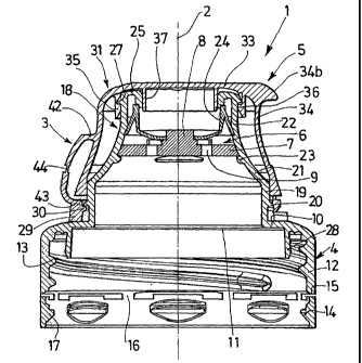
2C Reference is made first of all to Figures 4 to 6, which
depict a stopper 1 of axis 2, provided with a joining and
hinging element 3. The stopper 1 is for example produced
from plastics material.
The stopper 1 comprises on the one hand a base part 4,
intended to be mounted on a receptacle neck, and on the
other hand a part forming a cap 5 intended to be associated
with the base part 4.
The stopper 1 is described in a position where the axis 2 is
vertical, the part forming a cap 5 being situated above the
CA 02495191 2005-02-10
raised part 4. The axis 2 defines an elevation direction
with respect to which the terms "height", "top", "bottom"
are defined. A location close to the axis 2 is said to be
"internal", in contradistinction to a location at a distance
`i from the axis 2, said to be "external".
Naturally, the stopper 1 can take other positions in space,
in particular when it is used by a consumer.
The neck with which the stopper 1 is intended to be
associated has an opening through which the content of the
10 receptacle can pass. The neck comprises on its external
face a thread, projections forming attachments means,
situated under the thread, and a collar forming a support
surface, situated under the projections.
The receptacle can be flexible, so that a user, can, by
pressing on the said receptacle, assist the discharge of the
content. The receptacle can also be rigid.
The base part 4 of the stopper 1 is described first of all.
The base part 4, moulded in a single piece, is produced from
a relatively rigid plastics material.
The base part 4 comprises first of all an annular wall 10,
of axis 2, having at its centre a pouring orifice 11 with a
relatively large diameter, for example around three quarters
of the outside diameter of the annular part 10.
The base part 4 also comprises a cylindrical external skirt
12, projecting substantially perpendicular to the annular
wall 10 from the external edge thereof. The external skirt
12 is provided with an internal thread 13 able to cooperate
with the external thread on the neck.
In addition, an annular tamper-evident strip 14 produced in
CA 02495191 2005-02-10
11
a single piece with the base part 4, is connected to the
free end 15 of the external skirt 12 by breakable bridges 16
or by a line of lesser strength. The tamper-evident strip
14 comprises attachment projections 17, directed towards the
axis 2 of the stopper 1, and intended to cooperate with the
projections on the neck of the receptacle to enable the
tamper-evident strip 14 to be held on the said neck.
The base part 4 also comprises a funnel 18, projecting
substantially perpendicularly from the annular wall 10 from
the internal edge thereof, around the pouring orifice 11, in
the opposite direction to the external skirt 12.
The funnel 18 comprises first of all a substantially
cylindrical bottom portion 19, connected to the annular wall
10, and extending over approximately one third of the total
l~ height of the funnel 18. Approximately halfway up the
bottom portion 19, the external face of the funnel 18
comprises a projection 20 whose function will be described
later.
The funnel 18 also comprises an intermediate portion 21
2C extending from the top edge of the bottom portion 19 towards
to the top of the stopper 1 and towards the axis 2. The
intermediate portion 21 has substantially the form of a
truncated cone whose angle at the vertex is less than 90 ,
for example around 70 .
25 Finally, the funnel 18 comprises a substantially cylindrical
top portion 22, connected to the top edge of the second
intermediate portion 22, extending over approximately one
third of the total height of the funnel 18. The diameter of
the top portion 22, which defines the top opening of the
30 base part 4, is for example around one half the diameter of
the bottom portion 19.
CA 02495191 2005-02-10
12
In the junction area between the top portion 22 and the
intermediate portion 21, the funnel 18 can comprise an
internal element 6 intended to regulate the discharge flow
of the content of the receptacle.
`i The element 6 comprises first of all a discoidal part 7
placed substantially perpendicular to the axes 2, held
inside the funnel 18 by friction against the internal wall
of the said funnel 18 and by contact with an internal rim 23
on the funnel 18. The discoidal part 7 is for example
produced from polypropylene or high-density polyethylene.
The discoidal part 7 has a central stud 8 directed towards
the top portion 22 of the funnel 18, and at least one
orifice 9, situated at a distance from the stud 8, and
passing through the said discoidal part 7 so as to make the
1J inside of the receptacle provided with the stopper 1
communicate with the top opening of the base part 4 of the
stopper 1.
The element 6 also comprises a flexible membrane 24, for
example made from elastomer, situated in the immediate
vicinity of the discoidal part 7, on the same side as the
top portion 22 of the funnel 18.
The flexible membrane 24 has a central opening able to
cooperate with the stud 8 and also bears against the
internal face of top portion 22 of the funnel 18.
28 This stopper 1 is intended to be associated with a flexible
receptacle. Under the effect of the pressure exerted by a
user on the receptacle, the stopper 1 being turned over so
that the top opening of the base part 4 of the stopper 1 is
directed downwards, the flexible membrane 24 is deformed and
its central opening is released from the stud 8. Thus the
content of the receptacle can pass through the orifices 9 in
CA 02495191 2005-02-10
13
the discoidal part 7 and the central opening in the flexible
membrane 24.
When no pressure is exerted on the receptacle, the membrane
24 is in the position depicted in Figure 8, and the content
`i of the receptacle cannot emerge towards the top opening of
the base part 4 of the stopper 1.
In addition, the funnel 18 comprises an external rim 27
towards to the top part of the top portion 22. The function
of the external rim 27 is described later.
Finally, the funnel 18 has, at its top end part, a fold 25.
In addition, the base part 4 comprises an internal skirt 28
projecting substantially perpendicular from the annular wall
10 in the same direction as the external skirt 12. The
internal skirt 28 is intended to cooperate with the internal
face of the receptacle neck, for the purpose of
impermeability.
The part forming the cap 5 of the stopper 1 is now
described. The part forming the cap 5 is moulded in a
single piece and produced from a relatively rigid plastics
material.
The part forming a cap 5 comprises an annular ring 29
comprising at least one projection 5 on its internal face,
the said projection 30 being intended to cooperate with the
projection 20 on the funnel 18. The ring 29 can have a
continuous projection 30 or several projections 30 regularly
spaced apart on its internal face. Thus the ring 29 is kept
attached to the base part 4.
In addition the bottom edge of the ring 29 is situated in
the immediate vicinity of the annular wall 10 of the base
part 4 of the stopper 1.
CA 02495191 2005-02-10
14
The part forming a cap 5 also comprises a cover 31 connected
to the ring 29 by a joining and hinging element in the form
of a strap 3. The cover 31 is able to be moved between a
closed position, in which the cover 31 covers the funnel 18,
thus closing off the top opening of the base part 4 (Figures
4 and 5) , and an open position, in which the funnel 18 is
left clear, the said top opening not being closed off
(Figure 6).
The cover 31 comprises a top wall 33 - able to cover the top
opening of the base part 4 - from which there project,
substantially perpendicular and in the same direction:
- an external lateral wall 34 able to surround the funnel 18
when the cover 31 is in the closed position, and comprising
a front area 34a, substantially opposite to the hinge,
surmounted by a rim 34b, arranged to allow easy opening of
the cover 31 by simple action of the thumb;
- an external skirt 35, situated inside the cover 31,
provided with an internal rim 35 able to cooperate with the
external rim 27 on the top portion 22 of the funnel 18, thus
allowing closure by snapping the cover 31 onto the base part
4;
- an internal skirt 37, with a smaller diameter than that of
the external skirt 35, the said internal skirt 37 being able
to cooperate with the fold 25, for the purpose of sealing.
The various sealing means provided on the one hand between
the base part 4 and the neck (internal skirt 28 on the base
part 4) , and on the other between the base part 4 and the
part forming a cap 5 (internal skirt 37), provide a perfect
seal on the receptacle-stopper 1 assembly with respect to
the liquid contained in the receptacle, even if a user turns
the receptacle over when the cover 31 is in the closed
CA 02495191 2005-02-10
13
position.
In addition, the lateral wall 34 has a height such that,
when the cover 31 is the in the closed position, the free
edge 38 of the said lateral wall 34 is situated opposite the
bottom portion 19 of the funnel 18, for example
substantially halfway up the said bottom portion 19.
Thus the cover 31 and the funnel 18 cooperate sealingly on
the one hand close to the free edge 38 of the lateral wall
38 of the cover 31, and on the other hand in the vicinity of
the fold 25 of the funnel 18, via the internal skirt 37, so
that the space between the external face of funnel 18 and
the internal face of the cover 31 is closed and sealed,
therefore not being able to be attacked by an asepticising
liquid, neither from the inside nor from the outside of the
15% stopper.
Moreover, the height of the ring 29 is such that, when the
cover 31 is in the closed position, the top edge 39 of the
said ring 29 is situated in the immediate vicinity of the
free edge 38 of the cover 31, a very small and relatively
invisible space existing between them.
Before the cover 31 is first opened, the free edge 38 of the
lateral wall 34 of the cover 31 can be connected to the top
edge 39 of the ring 29, in particular by breaking bridges
40.
The strap 3 is now described.
The strap 3 has a first end 43 connected to the ring 29 and
a second end 42 connected to the cover 31.
The strap 3 is for example connected to the ring 29 close to
the top edge 39 of the said ring 29, the second end 42 of
the strap 3 being connected to the cover 31 at a significant
CA 02495191 2005-02-10
16
distance from the ring 29, for example close to halfway up
the height of the funnel 18. In addition, the distance
between the external face of the cover 31 and the internal
face of the strap 3 - opposite the cover 31 - is relatively
great.
Thus the space provided between the strap 3 and the cover 31
is relatively great, unlike the prior art, which helps to
allow effective rinsing of the stopper 1.
In the embodiments depicted, the strap 3 is substantially
rectangular in shape and is vertically broad. The height of
the strap 3 is for example between half and twice its
length. The width of the strap 3 can be close to the
diameter of the top portion 25 of the funnel 18.
The strap 3 is designed to allow moulding in the closed
position of the part forming a cap 5 as well as excellent
asepticisation of the stopper 1. This is because the strap
3 is "external" to the stopper 1 in that it does not require
any particular arrangement of the stopper 1 (strip 29 and
cover 31) at the ends 42, 43 of the strap 3. In particular,
no aperture is necessary on the ring or cover, and the strap
3 is not "integrated" in the ring or cover, but simply
connected to these.
In addition, the material making up the strap 3 is
sufficiently flexible to allow deformation of the said strap
3 in particular close to its ends 42, 43 (the strap 3
remaining however sufficiently strong).
Thus, as illustrated in Figure 6, the strap 3 enables the
cover 31 to be opened between around 130 at a minimum and
around 210 at a maximum, and enables the cover 31 to be
held in the open position, without it being necessary to
have recourse to a standard, more expensive, hinge, for
CA 02495191 2005-02-10
17
example of the butterfly type.
The hinge being produced by single element (the strap 3),
the use of such a hinge is also simple and inexpensive.
The strap 3 comprises two transverse hinge areas 47, 48 each
situated towards one end 42, 43 of the strap 3.
Thus the strap 3 has, for example, when the cover 31 is in
the closed position:
- a first substantially horizontal part, connected to the
external lateral wall 34 of the cover 31;
- a second substantially vertical part;
- a third substantially horizontal part, connected to the
ring 29.
A hinge area 47, 48 may be a weakening line situated at a
distance from the corresponding end 42, 43 of the strap 3
(Figure 9 for example) or situated in the immediate vicinity
of this end 42, 43 (Figure 8 for example).
This hinge area 47, 48 can be in the form of a localised
thinning produced from the internal face of the strap 3.
The hinge areas 47, 48 can also be obtained simply by the
2C use of a relatively flexible material for producing the
strap 3, to allow deformation of the said strap in
particular close to its ends.
According to one possible embodiment, the strap 3 also
comprises at least one - and for example a single --
transverse weakening area 44 situated between the two hinge
areas 47, 48, for example substantially halfway up the strap
3. This transverse weakening area 44 can be in the form of
a localised thinning. It is intended to assist the movement
CA 02495191 2005-02-10
18
of the strap 3 towards the open position of the cover 31 and
holding it in this position.
According to other embodiments, the strap 3 has no such
transverse weakening area 44.
Various embodiments of straps 3 are shown in Figures 7 to
12.
According a first embodiment (Figure 7, the base part 4 not
being shown) , the strap 3 has, in longitudinal section, the
shape of a U whose bottom is curved towards the outside of
the stopper 1, when the cover 31 is in the closed position.
The weakening area 44 is delimited by two arcs of a circle
45, 46 whose concavities are directed in opposite directions
to one another, the said weakening area 44 thus having
substantially the shape of a butterfly, with a reduced
1`> thickness with respect to the rest of the strap 3. This
thinning is here produced both from the internal and from
the external face of the strap 3.
According to a second embodiment (Figure 8), the strap 3
has, in longitudinal section, the shape of a U whose bottom
is directed aslant with respect to its arms, when the cover
31 is in the closed position. The weakening area 44 is here
also delimited by two arcs of a circle 45, 46 forming a
butterfly.
According to a third embodiment (Figure 9), the strap 3 has,
in longitudinal section, the shape of a U whose bottom is
curved towards the stopper 1, when the cover 31 is in the
closed position. The weakening area 44 is substantially
rectilinear.
Finally, according to a fourth embodiment (Figure 10), the
strap 3 has a longitudinal section in the shape of an arc of
circle when the cover 31 is in the closed position.
CA 02495191 2005-02-10
19
According to a fifth embodiment, the strap 3 is reinforced
by the addition of two lateral walls 49a, 49b. The strap 3
thus has a central longitudinal part 50 of thickness el,
comprising two transverse thinning areas 47, 48 each hinged
towards one of the ends 42, 43 of the strap 3, and two
lateral longitudinal parts 49a, 49b, situated on each side
of the central longitudinal part 50. These lateral
longitudinal parts 49a, 49b have a thickness e2 less that
the thickness el of the central longitudinal part and have
no transverse thinning area.
The width of each of the lateral longitudinal parts 49a, 49b
can be between 5% and 15% of the total width of the strap 3.
By way of example, the thickness e1 is around 0.7 mm, the
thickness of the transverse thinning areas 47, 48 around 0.2
mm and the thickness e2 greater than 0.2 mm. The width of
each of the lateral longitudinal part 49a, 49b can be around
1 mm.
The existence of the lateral longitudinal part 49a, 49b with
no transverse thinning areas makes it possible to avoid the
2C creation of a rupture initiation liable to weaken the strap
3.
Thus the minimum tensile strength of the strap 3 is 5 daN
(as opposed to approximately 50 N for the straps in Figures
7 to 10), the rotational strength also being improved, since
the strap 3 can be turned about its axis by 180 at a
minimum without breaking.
However, this structure makes it possible to keep an opening
in the cover 31 between 130 and 180 , since the thinning
areas 47, 48 are maintained.
The tamper-evident means according to the invention are
described with reference to Figures 13 to 23.
CA 02495191 2005-02-10
The ring 29 has, at a distance from the joining and hinging
device 3, at least one recess 51, formed from the top edge
39 of the ring 29, over a height less than the height of the
said ring 29. The width of the recess 51 is less than one
5 third of the length of the circumference of the ring 29. A
tamper-evident element is intended to be housed in the
recess 51 whilst being connected on the one hand at its
bottom part to the bottom of the recess 51 and on the other
hand at its top part to the cover 31.
10 The presence of this localised recess, at a distance from
the strap 3, affords much better visibility of the tamper-
evident element than in the stoppers of the prior art.
The height of the ring 29 is such that, when the cover 31 is
in the closed position, the top edge 39 of the said ring 29
15 is situated in the immediate vicinity of the free edge 38 of
the cover 31, the height of the tamper-evident element being
substantially equal to the height of the recess 51.
In addition, the particular deformation of the various
tamper-evident elements according to the invention enables a
20 user to see easily, or even immediately, whether the stopper
has already been opened.
Reference is made first of all to Figures 13 to 17, which
show a first embodiment of the tamper-evident element.
The recess 51 is substantially rectangular, with a height
for example close to the three quarters of the height of the
ring 29, and comprises a bottom 52 substantially parallel to
the top edge of the ring 29. The recess 51 is preferably
diametrically opposed to the strap 3, for better visibility
of the tamper-evident means.
The element forming a tamper-evident tell-tale 53 is housed
in the scollop 51. The tamper-evident element 53 has the
CA 02495191 2005-02-10
21
general shape of a substantially flat half disc delimited by
a rectilinear top edge 54 and by a bottom edge 55 in the
form of a semicircle, and having an internal face 56 and an
external face 57.
Naturally the stopper 1 according to the invention can
comprise several recesses 51 each associated with a tamper-
evident element 53.
The bottom edge 55 of the tamper-evident element 53 is
connected to the bottom 52 of the recess 51 by a
sufficiently flexible connection to allow the pivoting of
the said tamper-evident element 53 about the bottom 52 of
the recess 51.
To this end, the external face 57 of tamper-evident element
53 has, towards the bottom edge 55, a thinning 58, for
example produced from the external face of the tamper-
evident element 53, the connecting area between the tamper-
evident element 53 and the ring 29 being thereby reduced
compared with the total thickness of the ring 29.
The height of the tamper-evident element 53 is substantially
equal to the height of the recess 51, so that, before the
cover 31 is first opened, the top edge 54 of the tamper-
evident element 53 is situated so as to be continuous with
the top edge 39 of the ring 29.
Before the cover 31 is first opened, the top edge 54 of the
tamper-evident element 53 is connected to the free edge 38
of the lateral wall 34 of the cover 31 by a breakable bridge
59.
In addition, the tamper-evident element 53 comprises a
protrusion 60 on its internal face 56, the said protrusion
60 being compact with the external face of the bottom
portion 19 of funnel 18 before the cover 31 is first opened.
CA 02495191 2005-02-10
22
The dimensions of the protrusion 60 and the relative
positioning of the funnel 18 and tamper-evident element 53
are chosen so that, before the cover 31 is first opened, the
tamper-evident element 53 is forced towards the outside of
the stopper 1, by pressure of the protrusion 60 against the
funnel 18.
For this purpose, firstly, the breakable bridge 59 and the
connection between the tamper-evident element 53 and the
bottom 52 of the recess 51 are sufficiently strong to enable
the tamper-evident element 53 to be held in this position,
although the tamper-evident element 53 is subjected on the
part of the funnel 18 to a force directed towards the
outside.
Secondly, the material making up the base part 41 of the
stopper 1 and the material making up the part forming a cap
5 must be sufficiently rigid for neither the protrusion 60
nor the area of the funnel 18 situated opposite the
protrusion 60 to be deformed significantly, and for the
contact between the protrusion 60 and the funnel 18 to
generate a thrust force towards the outside of the stopper
1.
The way in which the tamper-evident element 53 enables a
consumer to check visibly and unambiguously that the cover
31 has not been opened is now described.
Before the cover 31 is first opened (Figures 5, 13 and 15)
the tamper-evident element 53 is connected to the free edge
38 of the side wall 34 of the cover 31 by the intact
breakable bridge 59. In addition, the protrusion 60 is in
contact with the funnel 18, the tamper-evident element 53
being forced towards the outside of the stopper 1.
When the cover 31 is first opened, the user acts on the
CA 02495191 2005-02-10
23
cover 31, pulling it and moving it, via the strap 3, to the
open position. The breakable bridges 40 connecting the free
edge 38 of the lateral wall 34 of the cover 31 to the top
edge 39 of the ring 29, on one hand, and the breakable
bridge 59 connecting the tamper-evident element 53 to the
free edge 38 of the lateral wall 34 of the cover 31, on the
other hand, are broken.
The tamper-evident element 53 is then no longer connected to
the cover 31. Because of the forcing of the tamper-evident
element 53 towards the outside, via the protrusion 60
cooperating with the funnel 18, and the flexible connection
between the bottom edge 55 of the tamper-evident element 53
and the bottom 52 of the recess 51, the tamper-evident
element 53 is pushed towards the outside of the stopper 1
and pivots about said flexible connection.
When the cover 31 is once again in the closed position, the
tamper-evident element 53 keeps this position (Figures 16
and 17).
The tamper-evident element 53 is then situated in a position
such that the thinning 58 is substantially in contact with
the bottom 52 of the recess 51, of the protrusion 60 no
longer being in contact with the funnel 18.
Thus the fact that the cover 31 has already been opened is
perfectly visible, since the free ends 67, 68 of the two
parts of the tamper-evident element 53 formed by the
breaking of the bridge 59 are distant from one another
significantly, following on from the pivoting of the said
tamper-evident element 53.
When the stopper 1 is looked at sideways (Figures 6 and 17),
it can be seen clearly that the tamper-evident element 53 is
projecting towards the outside of the stopper, rather than
CA 02495191 2005-02-10
24
housed in the recess 51, in contact with the funnel 18.
In addition, when the stopper 1 is looked at "front on",
that is to say in the direction of the tamper-evident
element 53, a space 61 appears between the free edge 38 of
the lateral wall 34 of the cover 31 and the top edge 54 of
the tamper-evident element 53 (Figure 16).
Because of the pivoting of the tamper-evident element 53
about the bottom 52 of the recess 51, this space 61 is
relatively large, and in any event with dimensions greater
than the space generally existing between a tamper-evident
strip and a cover. By way of comparison, the breakage of
the bridges 40 between the ring 29 and the cover 31 is not
as clearly visible.
In the variant illustrated in Figure 14, the recess 51 is
l~ also substantially rectangular and comprises a bottom 52, as
well as two lateral walls 62.
The lateral walls 62 of the recess 51 extend aslant from the
external face of the ring 29 towards the internal face of
the said ring 29 and towards the tamper-evident element 53.
The structure on the one hand leaves clear the recess 51 for
better visibility of the tamper-evident element 53, and on
the other hand facilitates the removal of the part forming a
cap 5 from the mould, not creating any undercuts.
Reference is now made to Figures 18 to 20, which depict a
second embodiment of the tamper-evident element.
The tamper-evident element 53 is in the form of a rod whose
end 63 fixed to the ring 29 and end 64 fixed to the cover 31
are offset with respect to one another along the
circumference of the stopper 1. Thus the overall axis 65 of
the rod is inclined with respect to the axis 2 of the
CA 02495191 2005-02-10
23
stopper 1. The axis 65 of the rod is for example inclined
by an angle of between 30 and 60 with respect to the axis
2 of the stopper 1.
The rod is housed in a recess 51, the end 63 of the said rod
being connected to the bottom 52 of the recess 51. The
distance between the ends 63, 64 of the rod is less than the
width of the recess 51.
The rod has a substantially polygonal cross section but
could also have a circular cross section. The cross section
of the rod is smaller at its substantially middle part 66
than at its ends 63, 64.
When a user opens the cover 31, thereby moving away the two
ends 63, 64 of the rod, the rod extends and its axis 65
tends to be oriented parallel to the axis 2 of the stopper
1. Locally, at the ends 63, 64, the rod pivots.
At a certain angle of opening of the cover 31, the strength
limit of the rod is reached. The rod is then broken, at its
smallest cross section, that is to say substantially at its
middle.
However, the rod keeps the deformation resulting from the
opening movement of the cover 31, particularly at its ends
63, 64, where the two parts resulting from the breakage of
the rod are locally substantially parallel to the axis 2 of
the stopper 1. As a result the two free ends 67, 68 of the
two parts of the rod are separated from one another. Such
would not have been the case with a conventional bridge,
oriented parallel to the axis 2 of the stopper 1: such a
bridge would have been deformed parallel to the axis 2, and
the two free ends resulting from the breakage of the this
bridge would thereby have been situated opposite one
another, substantially in contact, after the closure of the
CA 02495191 2005-02-10
26
cover 31.
Here, on the other hand, the pivoting of the rod at its ends
63, 64 has caused the non-alignment of the two parts of the
rod and the moving away of the two free ends 67, 68.
This embodiment also has the following advantages: removal
from the mould by slides in the mould, not requiring any
external reworking; flexibility of the rods when the part
forming a cap 5 is assembled on the base part 4, thereby
preventing the deformation or any breakage of the rods.
The stopper 1 can comprise several recesses 51 each provided
with a tamper-evident element 53 in the form of a rod. For
example, unlike the strap 3, two rods are provided. These
rods are situated at a distance from one another and
inclined symmetrically (Figure 18). The stopper 1 can also
comprise four recesses 51 regularly distributed at the
periphery.
Finally, reference is made to Figures 21 to 23, which depict
a third embodiment of the tamper-evident element.
The stopper 1 comprises here two recesses 51 whose bottom 52-
has a rounded shape, each recess 51 being provided with a
tamper-evident element 53. The recesses 51 are each
situated at 90 from the strap 3.
The tamper-evident element 53 is in the form of a rod whose
end 69 fixed to the ring 29, at the bottom 52 of the recess
51, and whose end 70 fixed to the cover 31, are offset with
respect to one another along the circumference of the
stopper 1. Thus the overall axis of the rod is inclined
with respect of the axis 2 of the stopper 1.
For example, the rod has a first substantially linear area,
extending from its end 69, fixed to the ring 29 over at
CA 02495191 2005-02-10
27
least two thirds of the height of the recess 51. This first
area is inclined with respect to the axis 2 of the stopper 1
by an angle of between 20 and 50 . The first area is
extended by a second slightly curved area, and inclined
overall by angle of between 50 and 70 , extending towards
and as far as the end 70 of the rod fixed to the cover 31.
The rod has for example a circular cross section, and this
cross section is smaller in the vicinity of its end 70
connected to the cover 31.
In addition, the cover 31 has an appendage 71 extending
towards the ring 29. The appendage 71 is directed aslant,
substantially parallel to the overall axis of the rod.
The appendage 71 has for example the shape of a triangle
whose base is substantially merged with the free edge 38 of
the lateral wall 34 of the cover 31, whose side 72 facing
the rod is substantially parallel to the rod, and whose side
73 opposite to the side 72 has a curved shape complementary
to the shape of the bottom 52 of the recess 51.
The tip 74 of the appendage 71 is situated in the vicinity
of but at a distance from the end 69 of the rod fixed to the
ring 29.
The first opening of the cover 31 results in the rupture of
the rod, at its end 70 connected to the cover (the area with
the smallest cross section) . When the cover 31 is closed
again, the appendage 71 comes into contact with the broken
rod, and moves it in order to bend it towards the ring 29.
When the cover 31 is in the closed position, the rod is
retained between the bottom 52 of the recess 51 and the side
73 of the facing triangle.
Because of this, the free ends 67, 68 of the two parts of
CA 02495191 2005-02-10
28
the rod are formed following the rupture of the rod are
distant from each other, the space between them being
sufficiently great to be able to be easily detected by a
user.
According to one possible embodiment, the stopper 1
comprises two rods whose ends 70 close to the smallest cross
section of the rod are situated at a distance from one
another and whose other ends 69 are substantially adjacent.
These rods are inclined substantially symmetrically, so as
to form a V, as depicted in Figure 22. The stopper 1
comprises two appendages 71 situated outside the V.
In addition, a projecting area of material 75 is provided on
the free edge 38 of the cover 31 in order to extend, between
the two rods, towards the ring 29. This area 25 serves in
l5 particular as a means of reinforcing the stopper 1.
Naturally, the tamper-evident element 53 can be reversed,
the smallest cross section of the rod being able to be close
to its end connected to the ring, and the appendage
extending from the ring towards the cover. After the first
opening of the cover, the rod is bent towards the said
cover.
In addition, the very great visibility of the loss of
tamper-proofness conferred by the invention can be greatly
increased if the base part 4 and part forming a cap 5 of the
stopper 1 are produced in different colours. This can
achieved very simply since the two parts of the stopper 1
are moulded separately. Thus the space 61 is the same
colour as the base part 4 and stands out clearly from the
cover 31 and the ring 29, both in the same colour different
from the colour of the base part 4.
In addition to the many aesthetic possibilities, the
CA 02495191 2005-02-10
29
production of a stopper 1 in two colours affords better
visibility of the tamper-evident means, and this in an
immediate way.
The invention has other advantages. In particular, the
cover 31 is captive, since it is associated with the base
part 4 of the stopper 1 via the strap 3 and the ring 29.
The tamper-evident element 53 is also captive, since it
remains connected to the ring 29. This presents in
particular additional safety vis-a-vis children, who cannot
1C) raise the said tamper-evident element 53 to their mouths.
Naturally, the various embodiment described can be combined
with each other, the invention not being limited to the
particular configurations depicted in the drawings.