Note: Descriptions are shown in the official language in which they were submitted.
CA 02495205 2005-02-10
WO 2004/018121 PCT/US2003/020363
ALUMINUM AEROSOL CAN AND ALUMINUM BOTTLE AND METHOD
OF MANUFACTURE FROM COIL FEEDSTOCK
Background of the Invention
Field of the Invention
[0001] The present invention is directed to aerosol cans and, more
particularly, to aerosol cans constructed of aluminum.
Description of the Background
[0002] Traditionally, beverage cans begin as disks of aluminum coil
feedstock that are processed into the shape of a beverage can. The sides of
these
cans are approximately 0.13 mm thick. Generally, the body of a beverage can,
excluding the top, is one piece.
[0003] In contrast, aerosol cans are traditionally made one of two ways.
First, they can be made from three pieces of steel, a top piece, a bottom
piece,
and a cylindrical sidewall having a weld seem running the length of the
sidewall.
These three pieces are assembled to form the can. Aerosol cans may also be
made from a process known as impact extrusion. In an impact extrusion process,
a hydraulic ram punches an aluminum slug to begin forming the can. The sides
of the can are thinned to approximately 0.40 mm through an ironing process
that
lengthens the walls of the can. The rough edges of the wall are trimmed and
the
can is passed through a series of necking dies to form the top of the can.
Although aerosol cans made of steel are less expensive than aerosol cans made
by an impact extrusion process, steel cans are aesthetically much less
desirable
than aerosol cans made with an impact extrusion process.
[0004] For a variety of reasons, aluminum aerosol cans are significantly
more expensive to produce than aluminum beverage cans. First, more aluminum
is used in an aerosol can than in a beverage can. Second, the production of
aluminum cans by impact extrusion is limited by the maximum speed of the
-1-
CA 02495205 2005-02-10
WO 2004/018121 PCT/US2003/020363
hydraulic ram of the press. Theoretically, the maximum speed of the ram is 200
strokes/minute. Practically, the speed is 180 slugs/minute. Beverage cans are
made at a rate of 2,400 cans/minute.
[0005] One problem facing the aerosol can industry is producing an
aluminum aerosol can that performs as well or better than traditional aerosol
cans but is economically competitive with the cost of producing steel aerosol
cans and aluminum beverage cans. Another problem is producing an aerosol can
that has the printing and design quality demanded by designers of high-end
products. Traditional beverage cans are limited in the clarity of printing and
design that can be imprinted on the cans. Beverage cans are also limited in
the
number of colors that can be used in can designs. Thus, a need exits for an
aluminum aerosol can that has the attributes of strength and quality, while
being
produced at a cost that is competitive with steel aerosol cans.
[0006] Producing aluminum cans of a series 3000 aluminum alloy coil
feedstock solves some of these problems. Series 3000 aluminum alloy coil
feedstock can be shaped into a can using a reverse draw and ironing process,
which is significantly faster and more cost effective than impact extrusion,
aluminum can production. Additionally, series 3000 aluminum alloy is less
expensive, more cost effective, and allows for better quality printing and
graphics than the use of pure aluminum.
[0007] Unfortunately, certain obstacles arise in necking a series 3000
aluminum alloy can. Series 3000 aluminum alloy is a harder material than pure
aluminum. Therefore, cans made from series 3000 aluminum alloy are stiffer
and have more memory. This is advantageous because the cans are more dent
resistant, but it poses problems in necking the cans by traditional means
because
the cans stick in traditional necking dies and jam traditional necking
machines.
The solution to these obstacles is embodied in the method of the present
invention.
Summary of the Present Invention
-2-
CA 02495205 2005-02-10
WO 2004/018121 PCT/US2003/020363
[0008] This invention relates to a method for making and necking an
aluminum aerosol can from a disk of aluminum alloy coil feedstock where the
method is designed to, among other things, prevent the can from sticking in
the
necking dies. Additionally, this invention relates to the aluminum aerosol can
itself, which has a uniquely shaped profile and is made from aluminum alloy of
the 3000 series.
[0009] The aluminum can of the present invention is comprised of a
generally vertical wall portion having an upper end and a lower end, where the
upper end has a predetermined profile. A bottom portion, extending from the
lower end of the can, has a U-shaped profile around its periphery and a dome-
shaped profile along the remainder of the bottom portion. Preferably, the
generally vertical wall portion is approximately 0.20 mm thick, and the bottom
portion is approximately 0.51 mm thick in the area of the U-shaped profile.
[0010] The present invention is also directed to a method of forming a
neck profile in an aluminum can made of a series 3000 aluminum alloy, where
the can is processed with at least 30 different necking dies. This invention
solves
the problems of necking a series 3000 aluminum alloy can by increasing the
number of necking dies used and decreasing the degree of deformation that is
imparted with each die. A traditional aerosol can, made from pure aluminum,
which is 45 mm to 66 mm in diameter, requires the use of 17 or less necking
dies. A can made by the present invention, of similar diameters, made from a
series 3000 aluminum alloy requires the use of, for example, thirty or more
necking dies. Generally, the number of dies that are needed to neck a can of
the
present invention depends on the profile of the can. The present invention
processes the aluminum can sequentially through a sufficient number of
necking,
dies so as to effect the maximum incremental radial deformation of the can in
each necking die while ensuring that the can remains easily removable from
each
necking die.
[0011] There are several advantages of the can and method of the present
invention. Overall, the process is faster, less expensive, and more efficient
than
-3-
CA 02495205 2005-02-10
WO 2004/018121 PCT/US2003/020363
the traditional method of impact extrusion, aerosol can production. The
disclosed method of production uses a less expensive, recyclable aluminum
alloy
instead of pure aluminum. The disclosed can is more desirable than a steel can
for a variety of reasons. Aluminum is resistant to moisture and does not
corrode
or rust. Furthermore, because of the shoulder configuration of a steel can,
the
cap configuration is always the same and cannot be varied to give customers an
individualized look. This is not so with the present invention in which the
can
shoulder may be customized. Finally, aluminum cans are aesthetically more
desirable. For example, the cans may be brushed and/or a threaded neck may be
formed in the top of the can. Those advantages and benefits and others, will
be
apparent from the Description of the Preferred Embodiments within.
Brief Description of the Drawings
[0012] For the present invention to be easily understood and readily
practiced,
the present invention will now be described, for purposes of illustration and
not
limitation, in conjunction with the following figures, wherein:
[0013] FIG. 1 is a view of one example of an aluminum can formed by the
method of the present invention, partially in cross-section;
[0014] FIG. 2 is a cross-sectional view of the bottom portion of the aluminum
can of FIG. 1;
[0015] FIG. 3 is one example of a coil of aluminum alloy feedstock used for
this invention;
[0016] FIG. 4 is one example of the coil of aluminum alloy feedstock of FIG.
3 showing metal disks punched from it;
[0017] FIG. 5 is a single metal disk of FIG. 4 made of a series 3000 aluminum
alloy;
[0018] FIG. 6 illustrates the disk of FIG. 5 drawn into a cup;
[0019] FIG.s 7A - 7C illustrate the progression of the cup of FIG. 6
undergoing a reverse draw process to become a second cup having a narrower
diameter after completion of the reverse draw process;
-4-
CA 02495205 2005-02-10
WO 2004/018121 PCT/US2003/020363
[0020] FIG. 8 illustrates one example of a shaped bottom formed in the
second cup of FIG. 7C;
[0021] FIG.s 9A - 9D illustrate the progression of the second cup of FIG. 7C
or of FIG. 8 through an ironing and trimming process;
[0022] FIG. IOA shows the resulting shoulder profile of an aluminum can
after the can of FIG. 9D has passed through thirty-four necking dies used
according to
one embodiment of the present invention;
[0023] FIG. 10B illustrates the resulting shoulder of the can of FIG. 10A
after
it passes through the last necking die used according to one embodiment of the
present invention;
[0024] FIG.s 11A-11D are a sequence of views, partially in cross-section, of
the aluminum can of FIG. I OB as it undergoes one example of a neck curling
process;
[0025] FIG. 12A is an aluminum can of FIG. 11D having a tapered shoulder;
[0026] FIG. 12B is an aluminum can of FIG. 11D having a rounded shoulder;
[0027] FIG. 12C is an aluminum can of FIG. 11D having a flat shoulder;
[0028] FIG. 12D is an aluminum can of FIG. 11D having an oval shoulder;
[0029] FIG. 13 - FIG. 47 are a sequence of cross-sectional views illustrating
thirty-five necking dies used according to one embodiment of the present
invention;
[0030] FIG. 48 shows a cross-sectional view of the center guides for the first
fourteen necking dies used according to one embodiment of the present
invention;
[0031] FIG. 49 shows a cross-sectional view of the center guides for necking
dies number fifteen through thirty-four used for one embodiment of the present
invention;
[0032] FIG. 50 illustrates one example of a die holder with a compressed air
connection according to the present invention;
[0033] FIG. 51 shows an aluminum can of the present invention having a
brushed exterior, partially in cross-section;
[0034] FIG. 52 shows an aluminum can of the present invention having a
threaded aluminum neck, partially in cross-section; and
[0035] FIG. 53 shows an aluminum can of the present invention having a
threaded plastic outsert over the can neck, partially in cross-section.
-5-
CA 02495205 2005-02-10
WO 2004/018121 PCT/US2003/020363
Description of the Preferred Embodiments
[0036] For ease of description and illustration, the invention will be
described with respect to making and necking a drawn and ironed aluminum
aerosol can, but it is understood that its application is not limited to such
a can.
The present invention may also be applied to a method of necking other types
of
aluminum, aluminum bottles, metal containers and shapes. It will also be
appreciated that the phrase "aerosol can" is used throughout for convenience
to
mean not only cans, but also aerosol bottles, aerosol containers, non-aerosol
bottles, and non-aerosol containers.
[0037] The present, invention is an aerosol can and a method for making
aluminum alloy cans that perform as well or better than traditional aluminum
cans, that allow for high quality printing and design on the cans, that have
customized shapes, and that are cost competitive with production of
traditional
aluminum beverage cans and other steel aerosol cans. The target markets for
these cans are, among others, the personal care, energy drinks, and
pharmaceutical markets.
[0038] A one piece, aluminum aerosol can 10, as seen in FIG. 1, has a
generally vertical wall portion 12. The generally vertical wall portion 12 is
comprised of an upper end 14 and a lower end 16. The upper end 14 has a
predetermined profile 18, and a neck 19 that has been curled. Alternatively,
the
neck can be threaded (see FIG.s 52 and 53). The aluminum can 10 also has a
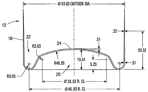
bottom portion 20 extending from the lower end 16. As shown in FIG. 2, the
bottom portion 20 has a U-shaped profile 22 around the periphery of the bottom
portion 20 and a wrinkle-free, dome-shaped profile 24 along the remainder of
the
bottom portion 20. The U-shaped profile 22 is preferably 0.51 mm thick.
[0039] The aluminum can 10 of the present invention is made from
aluminum alloy coil feedstock 26 as shown in FIG. 3. As is known, aluminum
alloy coil feedstock 26 is available in a variety of widths. It is desirable
to
-6-
CA 02495205 2010-07-28
.
design the production line of the present invention to use one of the
commercially available widths to eliminate the need for costly slitting
processes.
[0040] The first step in a preferred embodiment of the present invention
is to layout and punch disks 28 from the coil feedstock 26 as is shown in FIG.
4.
It is desirable to layout the disks 28 so as to minimize the amount of unused
feedstock 26. FIG. 5 shows one of the metal disk 28 punched from a series 3000
aluminum coil feedstock 26. The disk 28 is drawn into a cup 30, as shown in
FIG. 6, using any of the commonly understood methods of making an aluminum
cup, but preferably using a method similar to the method of U.S. Patents
5,394,727 and 5,487,295.
[00411 As shown in FIG. 7A, the cup 30 is then punched from the bottom
to begin to draw the bottom of the can through the sidewalls (a reverse draw).
As shown in FIG. 7B, as the stroke continues, the bottom of the cup 30 is
drawn
deeper so that the walls of the cup develop a lip. As shown in FIG. 7C, the
completion of the stroke eliminates the lip altogether resulting in a second
cup 34
that is typically narrower in diameter than the original cup 30. The second
cup
34 may be drawn one or more additional times, resulting in an even narrower
diameter. The resulting cup 34 has the vertical wall portion 12 and the lower
end
16 with the bottom portion 20. The bottom portion 20 maybe shaped as shown
in FIG.s 8 and 2. Although other configurations may be used, the domed
configuration illustrated herein is particularly useful for containers that
are
pressurized.
[00421 As shown in FIG.s 9A through 9D, the vertical wall portion 12 is
ironed multiple times until it is of a desired height and thickness,
preferably 0.21
mm thick. The vertical wall portion 12 should be of sufficient thickness to
withstand the internal pressure for the intended use. For example, some
aerosol
products require a can that withstands an internal pressure of 270 psi or DOT
2Q.
The ironing process also compacts the wall making it stronger. The upper end
14 of the vertical wall portion 12 is trimmed to produce an aluminum can 10,
as
shown in FIG. 9D.
-7-
CA 02495205 2005-02-10
WO 2004/018121 PCT/US2003/020363
[0043] According to one embodiment of the present invention, the can 10
is attached to a first mandrel and passed through a first series of necking
dies.
Subsequently, the can 10 is attached to a second mandrel and passed through a
second series of necking dies. In the embodiment illustrated, the can 10 will
pass through up to more than thirty necking dies. These necking dies shape the
can 10 as shown in FIG.s 10A and 10B. Each die is designed to imparta desired
shape to the upper end 14 of the generally vertical wall portion 12 of the can
10,
so that by the end of the necking process (FIG. 10B), the upper end 14 has the
desired profile 18 and the neck 19.
[0044] The can 10, partially shown in FIG. l OB, is shown in full in FIG.
1 1A. As shown in FIG.s 11A through 1 1D, the neck 19 of the can 10 is curled
through a series of curling steps. The resulting aerosol can 10 of the present
invention (as shown in both FIG. 1 1D and FIG. 1) has the predetermined
shoulder profile 18, the curled neck 19, and is adapted to receive an aerosol-
dispensing device. As shown in FIG.s 12A through 12D, the predetermined
shoulder profile 18 can be a variety of shapes including, that of a tapered
shoulder, a rounded shoulder, a flat shoulder, and an oval shoulder,
respectfully.
The resulting aluminum can may be between 100 and 200 mm in height and 45
and 66 mm in diameter. The aluminum can may be customized in a variety of
ways. One way would be to add texture the surface of the can, for example, by
brushing the surface of the can as shown in FIG. 51. Additionally, the
predetermined shoulder profile can be adapted to receive an aerosol-dispensing
device. The predetermined shoulder profile can also extend into or carry a
neck,
threaded or not (see FIG.s 52 and 53). An aluminum neck without threading can
carry a threaded plastic outsert, as shown in FIG. 53.
[0045] The present invention also encompasses a method of forming a
shoulder profile in an aluminum can made of a series 3000, e.g. 3004, aluminum
alloy. The first step of this method entails attaching the aluminum can to a
first
mandrel. The can is then passed sequentially through a first series of up to
and
including twenty-eight necking dies that are arranged on a necking table in a
circular pattern. The can is then transferred to a second mandrel. While on
the
-8-
CA 02495205 2005-02-10
WO 2004/018121 PCT/US2003/020363
second mandrel, the can is sequentially passed through a second series of up
to
and including twenty-eight necking dies which are arranged in a circular
pattern
on a second necking table. This method includes trimming the neck after the
can
passes through a certain predetermined number of necking dies. That is, one of
the necking dies is replaced with a trimming station. Trimming eliminates
excess material and irregular edges at the neck of the can and helps to
prevent
the can from sticking in the remaining necking dies. A sufficient number of
necking dies will be used so as to effect the maximum incremental radial
deformation of the can in each necking die that is possible while ensuring
that
the can remains easily removable from each necking die. Effecting the
maximum incremental radial deformation is desirable for efficient can
production. A problem arises when the deformation is too great, thus causing
the
can to stick inside the necking die and jam the die necking machine.
Generally,
at least 2 of radial deformation can be achieved with each die after the
first die,
which may impart less than 2 of the deformation.
[0046] The shape and degree of taper imposed by each die onto the can is
shown in FIG.s 13 through 47. The method of the present invention may use a
stationary center guide as shown in FIG. 48 for each of the first fourteen
necking
dies. FIG. 49 shows the center guides for the necking dies 15 through 34.
Compressed air can also be used to aid the removal of the can from the first
several necking dies. For other shoulder profiles, movable guides and
compressed air can be used on all necking positions. FIG. 50 shows a general
die holder with a compressed air connection.
[0047] The necking dies used in the method and apparatus of the present
invention differ from traditional necking dies in several ways. Each die
imparts
a smaller degree of deformation than the necking dies of the prior art. The
angle
at the back of the first necking die is 0 30'0" (zero degrees, thirty minutes,
zero
seconds). The angle at the backs of dies two through six is 3 instead of the
traditional30 . The necking dies of the present invention are also longer than
those traditionally used, preferably they are 100 mm in length. These changes
minimize problems associated with the memory of the can walls, which memory
-9-
CA 02495205 2005-02-10
WO 2004/018121 PCT/US2003/020363
may cause the can to stick in traditional necking dies. Additionally, in the
test
runs, the top of the can was pinched and was sticking on the center guide of
traditional dies. Therefore, the first fourteen necking dies have non-movable
center guides. Finally, the present invention uses compressed air to help
force
the cans off and out of each necking die. The compressed air also helps to
support the can walls.
[0048] While the present invention has been described in connection with
preferred embodiments thereof, those of ordinary skill in the art will
recognize
that many modifications and variations may be made without departing from the
spirit and scope of the present invention. The present invention is not to be
limited by the foregoing description, but only by the following claims.
-10-