Note: Descriptions are shown in the official language in which they were submitted.
CA 02495329 2005-O1-31
1
Description:
s Method for the design of a regulator for vibration damping at a lift cage
The invention relates to a method for the design of a regulator for vibration
damping at a
lift cage, wherein the regulator design is based on a model of the lift cage.
1o Equipment and a method for vibration damping at a lift cage has become
known by the
Patent Specification EP 0 731 051 B1. Vibrations or accelerations rising
transversely to
the direction of travel are reduced by a rapid regulation so that they are no
longer
perceptible in the lift cage. Inertia sensors are arranged at the cage frame
for detection of
measurement values. Moreover, a slower position regulator automatically guides
the lift
15 cage into a centre position in the case of a one-sided skewed position
relative to the guide
rails, wherein position sensors supply the measurement values to position
regulators.
A multivariable regulator for reducing the vibrations or accelerations at the
lift cage and a
further multivariable regulator for maintenance of the play at the guide
rollers or the upright
20 position of the lift cage are provided. The setting signals of the two
regulators are
summated and control a respective actuator for roller guidance and for
horizontal direction.
The regulator design is based on a model of the lift cage, which takes into
consideration
the significant structural resonances.
It is disadvantageous that the overall model has a tendency to a high degree
of
complexity, notwithstanding refined methods for reduction in the number of
poles. As a
consequence thereof the model-based regulator is equally complex.
3o Here the invention will create a remedy. The invention, as characterised in
claim 1, meets
the object of avoiding the disadvantages of the known method and of proposing
a simple
method for the design of a regulator.
Advantageous developments of the invention are indicated in the dependent
patent claims.
CA 02495329 2005-O1-31
2
Advantageously, in the case of the method according to the invention an
overall model of
the lift cage with known structure is predetermined. There is concerned in
that case a so-
termed multi-body system (MBS) model which comprises several rigid bodies. The
MBS
model describes the essential elastic structure of the lift cage with the
guide rollers and the
actuators as well as the force coupling with the guide rails. The model
parameters are
known to greater or lesser extent or estimates are present, wherein the
parameters for the
lift cage which is used are to be identified or determined. fn that case the
transfer
functions or frequency responses of the model are compared with the measured
transfer
functions or frequency responses. With the help of an algorithm for
optimisation of
1o functions with several variables the estimated model parameters are changed
in order to
achieve a greatest possible agreement.
Moreover, it is advantageous that the active vibration damping system of the
lift cage is
itself usable for the transfer functions or frequency responses to be
measured. The lift
cage is excited by the actuators and the responses are measured by the
acceleration
sensors or by the position sensors.
This model-based design method of the regulator guarantees the best possible
active
vibration damping for the individual lift cages with very different
parameters.
It is ensured by the above-mentioned identification method that as a result
the simplest
and most consistent model of the lift cage is present. Advantageously the
regulator based
on this model has a better grade or a better regulating quality. Moreover, the
method can
be systematically described and can be largely automated and performed in
substantially
shorter time.
Based on the MBS model with identified parameters a robust multivariable
regulator is
designed for reduction in the acceleration and a position regulator for
maintenance of play
at the guide rollers.
The acceleration regulator has the behaviour of a bandpass filter and the best
effect in a
middle frequency range of approximately 1 Hz to 4 Hz. Below and above this
frequency
band the amplification and thus the efficiency of the acceleration regulator
are reduced.
In the low frequency range the effect of the acceleration regulator is limited
by the
available play at the guide rollers and the position regulators to be designed
therefor. The
CA 02495329 2005-O1-31
3
position regulator has the effect that the lift cage follows a mean value of
the rail profiles,
whilst the acceleration regulator causes a rectilinear movement. This conflict
of objectives
is solved in that the two regulators are effective in different frequency
ranges. The
amplification of the position regulator is large in the case of low
frequencies and then
s decreases. This means that it has the characteristic of a low-pass filter.
Conversely, the
acceleration regulator has a small amplification at low frequencies.
In the high frequency range the effect of the acceleration regulator is
limited by the
elasticity of the lift cage. The first structural resonance can occur at, for
example, 12 Hz,
to wherein this value is strongly dependent on the mode of construction of the
lift cage and
can lie significantly lower. Above the first structural resonance the
regulator can no longer
reduce the acceleration at the cage body. The risk even exists that structural
resonances
are excited or that instability can arise. With knowledge of the dynamic
system model of
the regulator path the regulator can be so designed that this can be avoided.
The present invention is explained in more detail on the basis of the
accompanying
figures, in which:
Fig. 1 shows a multi-body system (MBS) model of a lift cage,
Fig. 2 shows a guide roller with roller forces,
Fig. 3 shows a setting element with guide roller, actuator and sensors,
2s Fig. 4 shows a schematic illustration of the regulated axes,
Fig. 5 shows the amplification of the measured acceleration and of the
identified
model,
3o Figs. 6 and 7 show an optimised regulator with the identified parameters
for active
vibration damping,
Fig. 8 shows a signal flow chart for the design of an H~ regulator with
regulator
and regulator path,
CA 02495329 2005-O1-31
4
Fig. 9 shows the course of the singular values of a position regulator in y
direction,
Fig. 10 shows the course of the singular values of an acceleration regulator
in y
direction and
Fig. 11 shows a force signal for excitation of the actuators.
The MBS model has to reproduce the significant characteristics of the lift
cage with respect
to travel comfort. Since in the case of identification of the parameters it is
possible to
operate only with linear models, all non-linear effects have to be
disregarded. The first
natural frequencies of the elastic lift cage are so low that they can overlap
with the so-
termed solid body natural frequencies of the entire cage.
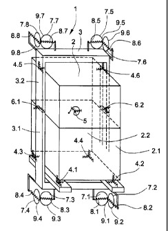
As shown in Fig. 1, at least two rigid bodies are required for modelling the
elastic lift cage
is 1, namely cage body 2 and cage frame 3. Cage body 2 and cage frame 3 are
connected
by means of elastomeric springs 4.1 to 4.6, the so-termed cage insulation 4.
This reduces
the transmission of solid-borne sound from the frame to the cage body. For
modelling a
rigid lift cage 1 it is sufficient to consider cage body and cage frame
overall as one body.
2o The transverse stiffness of cage body 2 and cage frame 3 is substantially
less than the
stiffness in vertical direction. This can be modelled by division in each
instance into at
least two rigid bodies, namely cage bodies 2.1 and 2.2 and cage frames 3.1 and
3.2. The
at least two part bodies are horizontally coupled by springs 5, 6.1 and 6.2
and can be
regarded as rigidly connected in vertical direction.
The guide rollers 7.1 to 7.8 together with the proportional masses of levers
and actuators
can be modelled by at least eight rigid bodies or also disregarded. This
dependent on the
associated natural frequencies of the guide rollers and on the upper limit of
the frequency
range which is considered. Since the natural frequency of the actuator/roller
system can
lead to instability in the regulated state, modelling by rigid bodies is
preferred. These are
displaceable relative to the frame only perpendicularly to the support surface
at the rail and
are coupled with the roller guide springs 8.1 to 8.8. In the other directions
they are rigidly
connected with the frame.
As is shown in Fig. 2, the guide behaviour or the force coupling between guide
rollers and
guide rails is important. Substantially only the two horizontal force
components are
CA 02495329 2005-O1-31
necessary for formation of the model. The vertical .force components, which
result from
the rolling resistance, can be disregarded. The normal force results from the
elastic
compression of the roller covering 9.1 to 9.8. The axial or transverse force
results from the
angle between the straight lines perpendicular to the roller axis and parallel
to the rail and
5 the actual direction of movement of the roller centre point.
Mathematically, the following relationships are relevant:
FRA = - tan( a )*FRN*K {1 }
1o FRA : rolling force in axial direction in [N]
a : oblique running angle in [rad]
FRN : rolling force normal to the support surface [N]
K : constant without dimension, determined by measuring
The force law {1} is at the latest invalid when the limits of the static
friction force are
reached as well as in the case of a large oblique running angle a . This is
rapidly greater
at low travel speed and at standstill amounts to approximately 90 degrees. The
force law
{1} thus applies only to the moving cage.
2o For the rolling force in axial direction with cage moving, there then
approximately applies:
F~ _ _ VA / VK * FRN * K
F~ _ _ VA *(FRN * K / VK)
vK : vertical speed of the cage [m/s]
vA : speed of the cage in axial direction [m/s]
K is a constant and vK and FRN can be regarded as constant when the biasing
force is
significantly greater than the dynamic proportion of the normal force. This
means that the
rolling force in axial direction is proportional and opposite to the speed in
axial direction
3o and conversely proportional to the travel speed of the lift cage.
Transverse vibrations of the cage are thus damped by the rollers like a
viscous damper,
wherein the effect is smaller with increasing travel speed.
CA 02495329 2005-O1-31
6
As shown in Fig. 3, the guide rollers 7 are connected with the cage frame 3 by
a lever 10
rotatable about an axis 10', wherein the roller guide spring 8 produces a
force between
lever and cage frame. An actuator 11 produces a force acting parallel to the
roller guide
spring. A position sensor 12 measures the position of the lever 10 or of the
guide roller 7.
An acceleration sensor 13 measures the acceleration of the lift cage 3
perpendicularly to
the support surface of the roller covering 9 on the guide rail 14. The
reference numerals of
the respective elements apply as shown in Fig. 1 (for example, at the lift
cage 1 at the
bottom on the right: 7.1, 8.1, g.1, 10.1, 11.1, 12.1, 13.1 ).
io Four lower guide rollers 7.1 to 7.4 together with actuators and position
sensors are
provided at the lift cage 1. 1n addition, four upper guide rollers 7.5 to 7.8
together with
actuators and position sensors can also be provided. The number of
acceleration sensors
13 required corresponds with the number of regulated axes, wherein at least
three and at
most six acceleration sensors are provided.
is
As shown in Fig. 4, for the active vibration damping of the lift cage 1 the
number of axes is
reduced from eight to six, or four to three axes when active regulation is
only at the
bottom. A triplet of signals Fn;, Pn;, an; for actuator force, position and
acceleration
belongs to each axis An;. The index i is the continuing numbering in the
respective axial
2o system and n stands for the number of axes of the system.
The signals of the lower and the upper roller pair between the guide rails
14.1 and 14.2 are
combined as follows: The force signal F6~ for the actuators 11.1 and 11.3 or
the force
signal F64 for the actuators 11.5 and 11.7 is divided into a positive and a
negative half.
zs Each actuator is controlled in drive only by one half and can produce only
compressive
force in the roller covering. A mean value is formed from the signals of the
position
sensors 12.1 and 12.3 and the same applies to the position sensors 12.5 and
12.7. A
mean value is similarly formed from the signals of the acceleration sensors
13.1 and 13.3
or 13.5 and 13.7. Since the acceleration sensors 13.1 and 13.3 or 13.5 and
13.7 lie on
30 one axis and are rigidly connected by the lower or upper cage frame, they
in principle
measure the same and in each instance one sensor of the respective pair can be
omitted.
In the case of measuring travels, one or more actuators is or are controlled
in drive by a
force signal as shown in Fig. 11 and the lift cage 1 is so excited to
vibrations transversely
35 the travel direction that clearly measurable signals arise in the position
sensors 12 and in
the acceleration sensors 13. So that the correlation of the measurements with
the force
CA 02495329 2005-O1-31
7
signals can be reliably determined, usually only one actuator or actuator pair
is controlled
in drive. As shown in Table 1 at least as many measuring travels are necessary
as active
axes are provided.
Table 1
Excitation: one or Measurements:
more
simultaneous) all simultaneous)
F6, P6, a6,
F62 P6z a62
F63 P63 a63
F64 P64 a64
F65 P65 a65
F66 P66 a66
The frequency spectrum of the force signals as well as the measured position
signals and
to acceleration signals are determined by Fourier transformation. The transfer
functions in
the frequency range or frequency responses G;,~ (~~ at the angular frequency ~
as
argument are determined in that the spectra of the measurements are divided by
the
associated spectrum of the force signal. In that case i is the index of the
measurement
and j is the index of the force.
GPi,i (CV) - F yCO~
J
G°i,.% y) - F. y
l
G(~~- GP(c~
G~ (~~
2o G~',,; (~~ are the individual frequency responses of force to position and
G°r,~ (r~~ are the
individual frequency responses of force to acceleration. The matrixGP(~~
contains all
frequency responses of force to position and matrixG°(~~ all frequency
responses of
CA 02495329 2005-O1-31
8
force to acceleration. The matrix G(w~ arises from the vertical combination of
G'~ (c~~ and
G~ (cr)~ .
For a 6-axis system there thus results 2 x 6 x 6 = 72 transfer functions and
for a 3-axis
system 2 x 3 x 3 = 18 transfer functions. In the case of cages having a centre
of gravity
lying on the axis between the guide rails 14.1 and 14.2 the couplings and the
correlation
between the two horizontal directions x and y are weak. For that reason only
approximately half the transfer functions is further used, the remaining being
excluded due
to inadequate correlation.
The MBS model of the cage is in general a linear system. If this contains non-
linear
components, a fully linearised model is produced in an appropriate operational
state by
numerical differentiation. In the linear state space the MBS model is
described by the
following equations:
x=Ax+Bu
y=Cx+Du
x is the vector of the states of the system, which in general are not
externally visible. The
states of the system in the present case are:
zo positions and speeds of the centre of gravity in the solid body model, as
well as rotational
angles and rotational speeds. Derivations of the states are speeds and
accelerations.
Speed is thus both state and derivation.
The vector X contains the derivations of x according to time. y is a vector
which
contains the measured magnitudes, thus positions and accelerations. The vector
a
contains the inputs (actuator forces) of the system. A , B , C and D are
matrices which
together form the so-termed Jacobi matrix by which a linear system is
completely
described. The frequency response of the system is given by
3o G~(co)=D+C(ju~I-A)-'B.
CA 02495329 2005-O1-31
9
G~~ (rv) is a matrix with the same number of lines as measurements in the
vector y and
the same number of columns as inputs in the vector a and contains all
frequency
responses of the MBS model of the cage.
A Jacobi matrix contains all partial derivations of a system of equations. In
the case of a
linear system of coupled differential equations of 1st order, these are the
constant
coefficients of the A, B, C and D matrices.
The model contains a number of well-known parameters such as, for example,
measurements and masses and a number of poorly known parameters such as, for
example, spring rates and damping constants. It is necessary to identify these
poorly
known parameters. The identification is carried out in that the frequency
responses of the
model are compared with the measured frequency responses. The poorly known
model
parameters are changed by an optimisation algorithm until the minimum of the
sum a of
i5 all deviations of the frequency responses of the model is found by the
measured frequency
responses.
e~,i W = I G',i O~ - I Gi.i (~~ . W(~
a - ~ ~ ~ Ler,i (~~~
i
w(~~ is a weighting dependent on frequency. It ensures that only important
components
of the measured frequency responses are simulated in the model.
An optimisation algorithm can be briefly circumscribed as follows: A function
with several
variables is given. A minimum or maximum of this function is sought. An
optimisation
algorithm seeks these extremes. There are many various algorithms, for example
the
method of fastest degression seeks the greatest gradients with the help of the
partial
derivations and rapidly finds local minima, but for that purpose can pass over
others.
Optimisation is a mathematical procedure used in many fields of expertise and
an
important area of scientific investigation.
CA 02495329 2005-O1-31
1~
Fig. 5 shows the frequency-dependent amplifications of the acceleration
measured and of
the identified model. ~Ga~. ~ ~ means amount or amplitude of the transfer
function or of the
frequency response of force to acceleration with the output acceleration from
axis 1 and
with the input force from axis 1. Dimension: 1 mg/N = 1 milli-g/N = 0.0981
m/s~2/N ~ 1
s cm/s~2/N.
Fig. 11 shows the force signal for excitation of the actuators 11. The
excitation is carried
out by a so-termed random binary signal, which is produced by means of a
random
generator, wherein the amplitude of the signal can be fixedly set, for example
to ~300 N,
1o and the spectrum is widely and uniformly distributed.
The model with the identified parameters forms the basis for the design of an
optimum
regulator for active vibration damping. Regulator structure and regulator
parameters are
dependent on the characteristics of the path to be regulated, in this case on
the lift cage.
15 The lift cage has a static and dynamic behaviour which is described in the
model.
Important parameters are: masses and mass inertia moments, geometries such as,
for
example, height(s), width(s), depth(s), track size, etc., spring rates and
damping values. If
the parameters change, then that has influence on the behaviour of the lift
cage and thus
on the settings of the regulator for vibration damping. In the case of a
classic PID
2o regulator (Proportional, Integral and Differential regulator) three
amplifications have to be
set, which can be readily managed manually. The regulator for the present case
has far
above a hundred parameters, whereby a manual setting in practice is no longer
possible.
The parameters accordingly have to be automatically ascertained. This is
possible only
with the help of a model which describes the essential characteristics of the
lift cage.
The regulation shown in Fig. 6 is divided into two regulators connected in
parallel:
A position regulator 15 and an acceleration regulator 16. Other structures of
the regulation
are alsa possible, particularly a cascade connection of position regulator and
acceleration
regulator as shown in Fig. 7. The regulators are linear, time-invariant, time-
discrete and
they regulate several axes simultaneously, hence the designation MIMO for
Mufti-Input,
Mufti-Output. n is the continuing index of the time step in a time-discrete or
'digital'
regulator.
The updated states x(n+1 ) fr the next time step are calculated so that they
are available
there.
CA 02495329 2005-O1-31
11
A dynamic system is time-invariant when the described parameters remain
constant. A
linear regulator is time-invariant when the system matrices A, B, C and D do
not change,
Regulators realised on a digital computer are always also time-discrete. This
means they
make the inputs, calculations and outputs at fixed intervals in time.
The so-termed H~ method is used for the regulator design. Fig. 8 shows the
signal flow
chart of the H~ design method with closed regulating loop. The main advantage
of the
H~ design method is that it can be automated. In that case the H~ standard of
the system
to to be regulated is minimised by closed regulating loop. The H~ of a matrix
A with m x n
elements is given by:
n
,IA,h = max ~ la;,,~ I (maximum 'lines sum')
i J=1
The system to be regulated is the identified model of the lift cage 1 with the
designation P
for plant as shown in Fig. 8. The desired behaviour of the regulator K with
the reference
numeral 17 is produced with the help of additional weighting functions at the
input and
output of the system.
- w~ models the interferences in the frequency range at the input of the
system
- w~ is a small constant value
- w~ limits the regulator output
- wy has the value one
2s Fig. 8 is a diagram for the design of the regulator by the H~ method. w is
the vector
signal at the input and is composed of v and r. z is the vector signal at the
output,
wherein z = T*w. T is composed of regulator, regulating path and weighting
functions. P6
or a6 forms the feedback in the closed regulating loop, in the case of
separate design of
position regulator or of acceleration regulator. F6 is the output or the
setting signal of the
3o regulator. The H~ standard is minimised by Ilzlh ~ IIWIh = IITII~~ For that
purpose there
is again necessary an optimisation algorithm which changes the parameters of
the
regulatar until a minimum has been found.
CA 02495329 2005-O1-31
12
Fig. 9 shows the course of the singular values of a position regulator in y
direction. This
has predominantly an integrating behaviour.
Fig. 10 shows the course of the singular values of an acceleration regulator
in y direction.
This has a bandpass characteristic.
Singular values are a measure for the overall amplification of a matrix. An n
x n matrix has
n singular values. Dimension: 1 N/mg = 1 N/milli-g = N/(0.0981 m/s~2) - 1
N/(cm/s~2).
to