Note: Descriptions are shown in the official language in which they were submitted.
CA 02495451 2005-02-15
WO 2004/020031 PCT/NZ2003/000193
~~HUMIDIFICATION SYSTEM"
BACKGROUND OF THE INVENTION
Field of the Invention
This invention relates to a humidification system, particularly but not
solely, for
supplying optimal humidity temperature of gases to a patient to assist the
patient's breathing
for ventilation purposes, or for the .supply of gases for other medical
procedures, such as
laparoscopic, endoscopic or ophthalmic procedures.
Summary of the Prior Art
A number of methods are known in the art for assisting a patient's breathing.
Continuous Positive Airway pressure or CPAP involves the administration of air
under
pressure to a patient, usually by a nasal mask. It is used in the treatment of
snoring and
Obstructive Sleep Apnea (OSA), a condition characterised by repetitive
collapse of the upper
airway during inspiration. Positive pressure splints the upper airway open,
preventing its
collapse. Treatment of OSA with nasal CPAP has proven to be both effective and
safe, but
CPAP is difficult to use and the majority of patients experience significant
side effects,
particularly in the early stages of treatment.
Upper airway symptoms adversely affect treatment with CPAP. Mucosal drying is
uncomfortable and may awaken patients during the night. Rebound nasal
congestion
commonly occurs during the following day, simulating a viral infection. If
untreated, upper
airway symptoms adversely affect rates of use.
Gases may also be supplied to patients suffering from Chronic Obstructive
Pulmonary
Disease (COPD). Also, at present there is no suitable means for home
humidification of
tracheotomy patients. These patients have by-passed upper airways and are
prone to infection
and congestion.
A number of methods may be employed to treat such symptoms, including
pharmacological agents to reduce nasal disease, or heating the bedroom. One
most commonly
employed method is humidification of the inspired air using an in line
humidifier. Two types
of humidifier are currently used. Cold pass-over humidifiers rely on
humidifying the air
through exposure to a large surface area of water. While they are cheap, the
humidity output
is low at high flows, typically 2 to 4 mg~I, absolute humidity at flows above
25Llmin. The
output is insufficient to prevent mucosal drying. Heated water bath
humidifiers are more
efficient, and produce high levels of humidity even at high flow rates. They
are effective at
CA 02495451 2005-02-15
WO 2004/020031 PCT/NZ2003/000193
2
preventing upper airway mucosal drying, prevent increases in nasal resistance,
and are the
most reliable means of treating upper airway symptoms.
Any of these active systems will have, to some degree or other, condensation
(or rain
out) in the tubing connecting the hmnidifier to the patient. The degree of
condensation is
strongly dependent on the ambient temperature, being much greater for greater
differences
between the ambient temperature and the gas temperature. The formation of
large quantities
of water in the breathing tubing causes considerable inconvenience to the
patient, may
accelerate cooling of the gas, may eventually occlude the tubing, or may be
expelled into the
patient. Also, the patient may experience discomfort, when breathing gases are
delivered at
temperatures widely divergent from that of the ambient temperature. Excessive
condensation
also results in inefficient usage of the water in the humidifying chamber.
In a hospital environment, where the ambient temperature of the atmosphere
within
the hospital environment is controlled by air conditioning for example, the
required
temperature for the humidified gases supplied by the apparatus may be
controlled within set
temperature parameters that are sufficiently close to the ambient temperature
to prevent
condensation within the conduit. However it is still necessary to have good
control over the
temperature and humidity of gases as they are actually supplied to the
patient.
In the home care environment in which a user requires to use humidifying
apparatus at
home, the range of ambient and gas temperatures may well exceed that of the
hospital
environment. In the home care environment, the user will usually wear a
facemask that is
connected to end of the conduit and such a humidifier may be used in the home
environment
for the treatment of breathing and sleep apnea disorders andlor in conjunction
with ventilators
or CPAP devices. In addition, non-active humidifiers are commonly employed
utilising the
known pass over humidification technique.
For medical procedures where a patient's cavity is inflated for surgery, such
as with
laparoscopic or endoscopic surgery, it is important that gases entering the
cavity are humid
and at body temperature so as not to cause drying of the cavity tissues and to
improve the
recovery time of the patient.
In US Patent No. 5640951 issued to Fisher and Paykel a heated conduit for a
humidified breathing assistance apparatus is disclosed which includes a
temperature probe at
the end of a heated conduit. By heating the conduit the problems relating to
condensation in
the conduit may be overcome. However in order to implement closed loop control
over the
temperature of the supplied gases (and therefore the power input to the
conduit heating
CA 02495451 2005-02-15
WO 2004/020031 PCT/NZ2003/000193
3
element 21), it is necessary to measure the temperature as close to the point
at which it is
supplied as possible. The temperature probe and its associated wiring included
for this
purpose make the attachment to the facemaslc or intubated patient bulky and
therefore more
uncomfortable for the patient. Also for other medical procedures the probes
and associated
wiring also result in bulky attachments at the operation entry point causing
obstructions to the
surgeon or pressure sores around the point of entry.
W001/13981 of Fisher & Paykel Healthcare Limited discloses a breathing
assistance
apparatus adapted to deliver humidified gases at a desired level of humidity
to a patient,
including a humidifier and a heated conduit. The humidifier includes a
controller, which
determines a parameter of gas flow rate and then the required power input to
the humidifier to
deliver the gases to the patient at the required patient humidity. In a second
embodiment, a
conduit heating element is provided and the controller determines whether it
has been
correctly connected to the control. The heater plate of the humidifier is
controlled to a
particular temperature (set point) or the heater plate power is controlled
through estimation or
measurement of flow and/or ambient temperature. The heating element within the
conduit is
controlled by controlling the power to the heater through measurement or
estimation of flow
and ambient temperature. This eliminates the need. for probes or external
sensors. The
blower or fan of this apparatus is pressure controlled for the purpose of
treating CPAP. With
this system the humidity of the gases supplied to the patient is not accurate,
particularly at
high flows.
DISCLOSURE OF THE INVENTION
It is an object of the present invention to provide a humidification system
which goes
some way to overcoming the abovementioned disadvantages or which at least
provides the
public or industry with a useful choice.
Accordingly in a first aspect the invention consists in a humidification
system adapted
to deliver humidified gases at a desired level of humidity, flow and
temperature to a patient
comprising:
(a) gases supply means providing a flow of gases,
(b) humidification means having an electrical input power and capable of
humidifying said gases up to a level of humidity prior to delivery to said
patient,
(c) flow measuring means that determines the flow of said gases before entry
of
said gases to said humidification means,
CA 02495451 2005-02-15
WO 2004/020031 PCT/NZ2003/000193
4
(d) humidity sensing means measuring the humidity of said gases before entry
of
said gases to said humidification means,
(e) first temperature sensing means measuring the temperature of the air
external
to said humidification system,
(f) transportation pathway means, having a heating means, said pathway means
conveying said humidified gases from said humidification means to said
patient, and
(g) control means including stored instructions to:
i) determine a transportation pathway heating means input power based
on at least said temperature of said air as measured by said first temperature
sensing means
and said flow of said gases as measured by said flow measuring means,
ii) determine a humidification means input power based on at least said
flow of said gases as measured by said flow measuring means and said humidity
of said gases
as measured by said humidity sensing means to achieve said desired humidity,
flow and
temperature of said gases, which are to be supplied to said patient.
In a further aspect the invention consists in a humidification system adapted
to deliver
humidified gases at a desired level of humidity, flow and temperature to a
patient comprising:
(a) gases supply means providing a flow of gases,
(b) humidification means having an electrical input power and capable of
humidifying said gases up to a level of humidity prior to delivery to said
patient,
(c) flow measuring means measuring the flow of said gases before entry of said
gases to said humidification means,
(d) humidity sensing means measuring the humidity of said gases before entry
of
said gases to said humidification means,
(e) first temperature sensing means measuring the temperature of the air
external
to said humidification system,
(f) second temperature sensing means measuring the temperature of said water
heating means,
(g) transportation pathway means, having a heating means, said pathway means
conveying said humidified gases from said humidification means to said
patient, and
(h) control means including stored instructions to:
i) determine a transportation pathway heating means input power based
on at least said temperature of said air as measured by~said first temperature
sensing means
and said flow of said gases as measured by said flow measuring means,
CA 02495451 2005-02-15
WO 2004/020031 PCT/NZ2003/000193
ii) determine a required temperature of said water heating means based on
at least said flow of said gases as measured by said flow measuring means and
said humidity
of said gases as measured by said humidity sensing means,
iii) determine the actual temperature of said water heating means from said
5 second temperature sensing means,
iv) vary input power of said water heating means to cause said actual
temperature to approach said required temperature to achieve said desired
humidity, flow and
temperature of said gases supplied to said patient.
In still a further aspect the invention consists in a humidification system
adapted to
deliver humidified gases at a desired level of humidity, flow and temperature
to a patient
comprising:
(a) gases supply means providing a flow of gases,
(b) humidification means having an electrical input power and capable of
humidifying said gases up to a level of humidity prior to delivery to said
patient and an inlet
receiving said gases from said gases supply means and outlet to pass said
gases to said patient,
(c) flow measuring means measuring the flow of said gases before entry of said
gases to said humidification means,
(d) humidity sensing means measuring the humidity of said gases before entry
of
said gases to said humidification means,
(e) first temperature sensing means measuring the temperature of the air
external
to said humidification system,
(f) ~ second temperature sensing means measuring the temperature of said gases
passing out said outlet,
(g) transportation pathway means, having a heating means, said pathway means
conveying said humidified gases from said humidification means to said
patient, and
(h) control means including stored instructions to:
i) determine a transportation pathway heating means input power based
on at least said temperature of said air as measured by said first temperature
sensing means
and said flow of said gases as measured by said flow measuring means,
ii) determine a required temperature of said gases passing out said outlet
based on at least said flow of said gases as measured by said flow measuring
means and said
humidity of said gases as measured by said humidity sensing means,
CA 02495451 2005-02-15
WO 2004/020031 PCT/NZ2003/000193
6
iii) determine the actual temperature of said gases passing out said outlet
from said second temperature sensing means,
iv) vary input power of said water heating means to cause said actual
temperature to approach said required temperature to achieve said desired
humidity, flow and
temperature of said gases supplied to said patient.
To those skilled in the art to which the invention relates, many changes in
construction
and widely differing embodiments and applications of the invention will
suggest themselves
without departing from the scope of the invention as defined in the appended
claims. The
disclosures and the descriptions herein are purely illustrative and are not
intended to be in any
sense limiting.
BRIEF DESCRIPTION OF THE DRAWINGS
One preferred form of the present invention will now be described with
reference to
the accompanying drawings in which;
Figure 1 is a schematic of the humidifier system of the present invention,
Figure 2 is detailed block diagram of the humidification system of the present
invention,
Figure 3 is an illustration of the oxygen port of the humidification system of
the
present invention, and
Figure 4 is a perspective view of the humidification system of the present
invention
when housed in one housing.
DETAILED DESCRIPTION OF THE PREFERRED EMBODIMENTS
Whether used in a hospital environment or in a home care environment, the
humidification system of the present invention will generally have associated
with it a gases
supply, such as ambient air, gases from cylinders, other compressed gas supply
or gases from
an insufflator, and a transport conduit from the humidification system to the
patient, which is
preferably heated to reduce condensation, or "rain out".
A heating element is preferably provided within the conduit to help prevent
condensation of the humidified gases within the conduit. Such condensation is
due to the
temperature of the walls of the conduit being close to the ambient
temperature, (being the
temperature of the surrounding atmosphere) which is usually lower than the
temperature of
the humidified gases within the conduit. The heating element effectively
replaces the energy
lost from the gases through conduction and convection during transit through
the conduit.
CA 02495451 2005-02-15
WO 2004/020031 PCT/NZ2003/000193
7
Thus the conduit heating element ensures the gases delivered are at an optimal
temperature
and humidity.
The humidification system of the present invention may be used for various
applications such as laparoscopic, ophthalmic or other surgical procedures,
tracheostomised
patients, and trans-tracheal insufflation. The humidification system of the
present invention
may be used in any treatments requiring or benefiting from the supply of a
humidified gas
supply.
The present invention provides a humidification system where the flow of gases
passes in sequence through a flow driver (such as, a blower, fan, compressor
or insufflator),
humidification chamber and then heated delivery circuit. This system is
contained such that
the measurements made to control the flow, humidity and temperature of gases
are internally
sensed, so that there are no external sensors or electrical leads to
components to hinder the
patient or operator. This not only saves the cost of the extra sensors but
also makes the
system simpler and easier to set-up, operate and clean.
Typical blower humidifier combinations have been designed for the treatment of
OSA
and are pressure-controlled devices. They are also typically designed to be
used as stand-
alone blowers or in combination with a simple humidifier. These therefore
typically deliver
low levels of humidity i.e. 28 to 32mg/L. The present invention is intended to
deliver body
temperature saturated gases (37°C and 44mg/L for room air) over a range
of flows that would
typically be used to provide for a patient's inspiratory flow requirements
(that is, peak
inspiratory flow).
The humidification system operates as a pressure limited, flow controlled
device, so it
adjusts the flow of gases to the level set by the patient. Therefore, this
system can be used to
deliver humidified gas for patients with bypassed airways, such as
tracheotomies or nasal
cannula or masks or for other systems that require high flow gases. This has
the potential to
benefit many patients in both the home and hospital environments.
The humidification system of the present invention provides a much more
accurate
control of the delivered gas condition through estimation or measurement of
any combination
of flow, humidity, temperature and pressure, prior to the humidification
chamber, and by use
of the sensed ambient temperature. A subsequent calculation of the required
heating element
power, heater plate temperature set point and/or heater plate power can then
be made to
achieve optimal humidity, temperature and flow. Clinical data exists to
suggest that gases at
CA 02495451 2005-02-15
WO 2004/020031 PCT/NZ2003/000193
8
37°C and containing 44mg of water vapour per litre at approximately
atmospheric pressure
are "optimal" for patient health.
The invention consists in a humidification system adapted to deliver
humidified gases
at a desired level of humidity, flow and temperature to a patient.
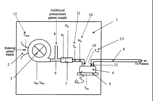
Referring to Figure 1, the flow of gases through the humidification system 1
passes
from the air within a room, through the inlet 2 (that may also include a
filter or the like) into
the internal fan unit 3 (blower or the like) then may be mixed with an
additional pressurised
gas supply 8 at junction 9 and then flow into humidification chamber 4 via an
inlet port 10. In
the preferred form of the humidification system the additional gas supply is
mixed with the
gases from the fan, but in other forms of the present invention no additional
gas supply is
provided.
Beneath the humidification chamber is a heater plate 5, which heats water held
within
the chamber 4. The gases exit the chamber 4 and pass out from the
humidification system 1
to a heated delivery circuit 6 and to a patient (not shown). A controller (not
shown) connects
and controls all the components mentioned above and will be described in more
detail below.
Referring to Figures 1 and 4, in the preferred embodiment the fan unit 3 and
humidifier, including chamber 4 and heater plate 5, and various controllers of
these, are
housed in one housing 13 and sensors, which are used to monitor various
internal parameters
of the fan, humidifier and gases, are internal within the housing 13, except
for the external gas
ambient air temperature sensor (Tamb) 12 that extends out slightly from the
housing 13 so as to
enable sensing of the ambient air surrounding the gases inlet 2.
In the preferred embodiment the humidification chamber extends out from the
housing
as shown in Figure 4, and is capable in use of being removed and replaced by
the patient or
other user. Also, the inlet port 10 to the humidification chamber 4 is
internal within the
housing 13. The inlet 2 to the housing 13 where gases are drawn from the
ambient air outside
the housing 13 is located at the end of the housing 13, but in actuality may
be located at any
appropriate point in the housing 13. It must be appreciated that the
embodiment described
above in relation to the housing and Figure 4 merely illustrate one form of
the housing of the
humidification system of the present invention.
In the preferred form of the present invention the fan 3 or flow source used
within the
humidification system is an electrically powered fan. Furthermore, it is
preferred that the
humidification chamber 4 sits atop an electrically powered heater plate 5 and
an electrically
powered heating element resides within the delivery circuit 6. These
embodiments have been
CA 02495451 2005-02-15
WO 2004/020031 PCT/NZ2003/000193
9
used for explanation purposes only. Any other suitable embodiment could have
the same
control scheme applied to it; for example, the fan could be replaced by a
compressor, the
chamber by a heated aerosol generator and the heater by a warm water jaclcet.
In the embodiment of the present invention as shown in Figures 1 to 4, an
orifice plate
7 is used as the flow sensor and pressure sensor. The orifice plate allows for
the measuring of
the pressure of the gases after the gases leave the fan. From these
measurements the velocity
(flow) of the gases can be calculated. However, it must be appreciated in
other forms of the
present invention, other flow sensing devices such as a venturi or hotwire
anemometer could
be used. Furthermore, in other embodiments the flow sensor and pressure
sensors taking
measurements after the fan may actually be separate sensors.
Controlling the Flow of Gases
Referring again to Figure 1, a portion or all of the total flow of gases
through the
humidification system 1 passes from the surrounding air within a room through
the inlet 2
(that may also include a filter or the like) into the internal fan unit 3.
Preferably the internal
fan unit 3 is an electric fan, which blows external surrounding air through
the humidification
system. A portion of the total flow may be supplied from an additional
pressurised gas supply
8, which mixes with the air at junction 9. Preferably the pressurised gas is
oxygen, such that
the air-oxygen mix delivered to the patient is rich in oxygen. Preferably the
user is able to
alter the concentration of oxygen.
Refernng to Figures 1 and 2, in the preferred embodiment the flow of gases
through
the humidification system 1 is measured by sensing the pressure on both sides
of an orifice
plate 7 situated as shown in Figure 1 after the fan 3 outlet and orifice plate
7. The pressure on
the fan 3 side of the orifice 7 is denoted P f and the pressure on the down
stream side is
denoted P;". This method of flow sensing is well known in the art and the
orifice plate can be
calibrated to give an accurate flow measurement, termed measured flow. The fan
speed Vfan
is then varied (by varying the power into the fan or the current to the fan
Ifan) so that the
measured flow of gases approaches the set flow as selected by the user.
Flow Sensor Checking
Correct operation of the flow sensor (orifice plate 7) can be monitored and
checked
by using less accurate flow estimation methods to find the operating flow
range, if the flow
sensor is outside of this range then the sensor is found to have failed. This
improves safety
and allows the device to be tolerant of some faults. The humidification system
may be able to
continue to operate or may cause an alarm to be signalled and the device to
switch to a safe
CA 02495451 2005-02-15
WO 2004/020031 PCT/NZ2003/000193
mode. The flow estimation method employed may be as described in WO 01/13981
of Fisher
& Paylcel Limited, the contents of which are herein incorporated, where the
flow is estimated
from the fan speed and the loading on the fan, or the flow can be estimated
from the
relationship between the sensed temperature of the heater plate and the power
drawn by the
5 heater plate.
Controlling the level of Humidity of Gases - Heater Plate Control
Referring to Figures 1 and 2, the flow of gases through the humidification
system 1
continues from the flow sensor 7, down a short conduit, past the temperature
sensor and
humidity sensor 16 into the humidifier chamber 4. The water within the
humidification
10 chamber 4 is in thermal contact with heater plate 5. The heating of the
water directly affects
the humidity output of the humidification chamber 4. Thus as the flow of gases
pass out of
the humidification chamber 4 exiting out the outlet port 11 the humidity level
contained in the
gases is affected by the electrical power input into the heating element (not
shown) of the
heater plate 5. Conversely, the humidity level contained within the gases is
affected by the
temperature of the water in the humidification chamber 4, or, as a result of,
the temperature of
the heater plate 5.
The humidity and flow of gases required to be delivered by the system to the
patient is
selected by the user, and thus the energy required to be delivered by the
humidification means
is known, as will be described below. The energy of the gases entering said
humidification
chamber 4 is also known from sensing flow, humidity and temperature by
respectively using a
flow sensor 14 (shown in Figure 1 as the orifice plate 7), humidity sensor 16
and temperature
sensor 15 before the humidification chamber 4. The basis of the humidity
control employed
in this invention is conservation of energy. The energy entering into and
energy exiting from
the humidification chamber 4 is known, therefore using conservation of energy
principles the
energy required to be added by the heater plate to ensure the required energy
exits the
humidification chamber 4 can be calculated.
In the preferred form of the humidification system the humidification chamber
has a
water autofeed mechanism that ensures the volume of water within the
humidification
. chamber remains constant at all times. Furthermore, this autofeed mechanism
ensures that the
heat capacity of the water remains constant, which further simplifies the
complexity of control
required of the humidifier. An humidification chamber with autofeed
capabilities that is
suitable for this application is described in US5445143 of Fisher & Paykel
Limited, the entire
contents of which is incorporated herein. In this autofeed chamber the water
level within the
CA 02495451 2005-02-15
WO 2004/020031 PCT/NZ2003/000193
11
large volumes of cold water over a short period of time. This greatly affects
the humidity
output of the chamber.
The humidifier is in a very steady state with a constant flow of gases and
small
amounts of water steadily being added to a chamber with low thermal inertia.
This steady
state allows application of the steady flow energy equation. The amount of
electrical power
required to be supplied to the heater plate can be calculated as below.
Qkp - Qout Qin
Where, Qo"t is constant as specified by the user and Q;" is the enthalpy of
the incoming gas
stream, which is dependent upon the temperature and humidity of the incoming
gas stream.
Therefore, Qlp = A + B ~ Haasaltrte + C ~ T,.,t
Where:
Qlp = Heater plate power,
Qorrt = Energy of gas passing out of chamber,
Q;" = Energy of gas passing into chamber,
Habsolrrte = Absolute Humidity at inlet of humidification chamber,
T,." = Gas temperature at inlet of humidification chamber,
A, B, C, D, E & F = Constants found experimentally for a specific flow and
output humidity
level, and
T,,p = Heater plate temperature
Alternatively the heater plate set point temperature can be calculated using:
T,p = D + E ~ Habsor,rte + F ~ T,1
In this equation the constants take account of the thermal resistances within
this specific
system and are found experimentally.
The user selects the desired flow and humidity options to be delivered, for
example
40L/min & 44mg/L, the heater plate controller 17 uses the constants known for
this
combination of options (i.e. D = 96.37, E = -0.79, F = -0.22) and measures the
temperature
and humidity level of the gases coming into the humidification means (for
example T;
35°C, Habs°nte 8.75mg/L) then the heater plate temperature set
point is calculated as below.
T,p = 96.3 7 - 0.79 ~ Habsot,rte - 0.22 ~ T,. t
T,p =96.37-0.79x8.75-0.22x35
CA 02495451 2005-02-15
WO 2004/020031 PCT/NZ2003/000193
12
T,,p = Heater plate temperature
Alternatively the heater plate set point temperature can be calculated using:
T,,p = D + E - H"Gsolu~~ + F ~ T"
In this equation the constants take account of the thermal resistances within
this specific
system and are found experimentally.
The user selects the desired flow and humidity options to be delivered, for
example
40L/min & 44mg/L, the heater plate controller 17 uses the constants known for
this
combination of options (i.e. D = 96.37, E = -0.79, F = -0.22) and measures the
temperature
and humidity level of the gases coming into the humidification means (for
example T;p
35°C, Habsoiute 8.75mg/L) then the heater plate temperature set point
is calculated as below.
T,,p = 96.37 - 0.79 ' Habsolute - 0.22 ~ T,."
Thp =96.37-0.79x8.75-0.22x35
Thp = 81.66 °C
When there are gases at 35°C containing 8.75mg/L of water vapour, and
these gases are
flowing into the humidification chamber at 40L/min, the heater plate
temperature set point is
calculated to be 82°C. When the sensed heater plate temperature
approaches its set point the
humidity output from the chamber approaches 44mg/L.
It will be appreciated that a further embodiment of the invention could
incorporate a
sensor on the outlet of the humidification means to allow closed loop control
as is known in
the art. The novel concepts of the present invention could be incorporated to
such a system to
allow advances in the therapy. Many current humidifiers use temperature
sensors or the like
on the outlet, make an assumption that gases are close to saturated, and then
control to a dry-
bulb temperature set point. The assumption of saturation is incorrect for some
inlet
conditions, for example high inlet temperature or humidity, and this can cause
the delivered
absolute humidity to deviate widely from the desired or optimal level. This
further
embodiment of the present invention would operate under the common closed loop
control
method with the addition of a humidity sensor at the inlet of the
humidification means. The
information provided by such a sensor would allow an estimate of the correct
dry-bulb
temperature set point necessary to achieve the desired level of absolute
humidity. Calculation
of this set point would be similar in method and principle to the calculation
described above.
CA 02495451 2005-02-15
WO 2004/020031 PCT/NZ2003/000193
13
This humidification system of this embodiment would be considerably more
reliable in its
delivery of saturated gases than currently available humidifiers.
In particular, Figure 1 shows such an additional temperature sensor 23 that
may be
provided at the outlet 11 to the humidifier chamber 4 to determine the
temperature of the
gases leaving the humidification chamber. The sensor Tout 23 would preferably
be provided
within the outlet or humidifier housing, so that no external wiring leads to
the sensor 23. This
sensor 23 could be used in much the same manner as is described above to
control humidity
output. In fact, either the measurement of the heater plate temperature or
temperature of the
gases leaving the chamber could be used to control humidity output. In this
case, the other of
the two that is not being used to control humidity output could be used as a
safety check
which would switch the humidification system off if a temperature higher than
a threshold
was sensed.
Controlling Humidity and Temperature of Gases - Heated Delivery Circuit
Control
As shown in Figures 1 and 2, the flow of gases exit the chamber 4 and pass out
from
the humidification system 1 to a heated delivery circuit 6 and to a patient
22. The heated
delivery circuit 6 is a plastics conduit having a heated wire 21 extending
through it, for
example, such as that disclosed in any one of NZ516387, NZ514314 and NZ521017,
all of
Fisher & Paykel Healthcare Limited, the contents of which are incorporated
herein. The
delivery conduit has wires extruded within the tubing walls. The conduit is
extruded from an
appropriate plastics material, such as a flexible polymer. The conduit has
ridges or ribs
extending from the surface of the conduit wall. Each rib extends towards the
centre of the
conduit and has a heating element, usually a wire that is embedded along the
conduit's length.
The heater wires may be made from copper, copper alloy or other appropriate
electricity
conducting material, such as a PTC heater. The heater wire is embedded within
the ribs of the
conduit by co-extrusion at the time the polymer conduit is extruded.
The heated delivery circuit 6 controls the temperature of the gases received
by the
patient 22. Both the temperature of the gases delivered to the patient, and
the temperature of
the gases at any point within the conduit are controlled. In order to
transport the humidified
gases produced from the humidification chamber the gases must be kept above
the dew point
temperature at any point within the delivery circuit in order to be able to
transport all of the
water vapour and avoid condensate. Referring to Figure 2, the conduit heater
controller 18
calculates the power required to be used to heat the delivery conduit 6 for a
specific humidity
setting and flow setting based off the ambient temperature Tamb of the room.
This ambient
CA 02495451 2005-02-15
WO 2004/020031 PCT/NZ2003/000193
14
temperature is measured by the temperature sensor 12 (see Figure 1) at the fan
inlet 2 and
enables the gauging of the amount of heat loss from the delivery conduit 6 to
the surrounding
ambient conditions. The relationship between said ambient temperature and the
power used
to heat the delivery conduit 6 in order to achieve the desired temperature at
the patient is
found experimentally.
Oxygen Mixing
Referring to Figure 3, the humidification system of the present invention in
the
preferred form incorporates an external port for the mixing of additional
gases, preferably
oXygen, into the gases flow. The port 40 is connected to a pressurised oxygen
source and
thereby causes oxygen to be added to the gases flow through the humidification
system at a
point before the humidifier, but after the fan 3.
It is usual to use a blender to mix the air and oxygen, however this requires
both a
compressed oxygen and air supply which is commonly not available, a blender is
also
expensive and thus adds a large additional cost. The other common method of
mixing air and
oxygen is an air entrainer. An air entrainer operates by using a high velocity
jet of oxygen to
shear past surrounding room air, which draws in some of this surrounding air
and creates a
mixed flow of gases down stream. The main disadvantage of an air entrainer is
that if the
downstream conduit has a large resistance to flow then the air entrainer is
unable to generate a
driving pressure to overcome this, and thus can't generate a flow. As. the
preferred
embodiment of the present invention includes a long flexible conduit to
deliver the gases to
the patient, an air entrainer will not function in this circumstance.
In the preferred embodiment of the humidification system to measure the oxygen
concentration of the gases flowing through the system either an oximeter (not
shown) is
provided in the mixed gas stream in a similar location to that of 42 or three
flow meters 41,
42, 43, one each on the inward flowing oxygen stream 41, gases flow from the
fan 43 and
mixed gases flow 42 are provided. Any one of these three sensors are redundant
for safety,
the total flow and oxygen concentration can be calculated from any two of
these sensors and
should any one of these sensors fail these quantities are still known. As
oxygen can be toxic
in high concentrations it is important that this measurement is correct. It is
displayed on the
unit and clinical decisions may be made from this information. In order to
allow for
flexibility of the volume inputted into the gases flow, at the oxygen port 40
a needle valve 44
with a flow control lrnob is provided. This allows a user to alter the volume
of the oxygen
CA 02495451 2005-02-15
WO 2004/020031 PCT/NZ2003/000193
flow into the humidification system and ultimately the concentration of oxygen
inspired by
the patient.
Overheating Detection
The humidification system of the present invention includes within the conduit
heater
5 plate controller 18 a delivery conduit overheating detection system, such as
that disclosed in
NZ516387 of Fisher & Paykel Healthcare Limited, the contents of which are
herein
incorporated. Such a detection system for the heating element includes a
method of detecting
conduit overheating where, when the conduit is hot the current drawn by the
heating element
within the conduit exceeds a predetermined limit. The detection system ensures
that the
10 humidifier and conduit can be switched to a safe mode then back to an
operating mode once
the temperature of the heating element within the conduit has reduced to safe
levels. The
device comprises a sensor to detect the current in the heating element and
controller that
implements an algorithm to reduce the current in the heating element to a safe
current region.
If the conduit comprises two limbs the sensor detects the currents in each of
the limbs
15 determines the difference between these currents and if the difference
approaches a
predetermined limit then the power to each of the heating elements is reduced.
Electro Pneumatic Connector
In the preferred form of the humidification system of the present invention
the
delivery conduit 6 is connected to the output port 11 by way of an electro
pneumatic
connector, such as that described in NZ519374 of Fisher & Paykel Healthcare
Limited, the
contents of which is herein incorporated. In particular a connector of this
type is utilised
where the conduit has a heating element or electrical wire extending within,
throughout and
about it. The conduit is connected to the humidification chamber via a
connector that
provides both an electrical 19 and a pneumatic 20 coupling. In Figure 4, only
the chamber 4
side of a single port electro pneumatic connector is shown. In this form the
single port
connector is generally tubular and has a male and female portion where the
pneumatic
coupling is by a threaded, sliding collar or bayonet type connection that has
an integral
electrical port that provides power to the wire in the conduit.