Note: Descriptions are shown in the official language in which they were submitted.
CA 02495677 2005-02-15
WO 2004/026776 PCT/US2003/027548
GLASSWARE FORMING MACHINE CONTROL SYSTEM
The present invention is directed to glassware forming machine systems, and
more
particularly to an integrated and networked electronic control for a glassware
forming machine
system.
Background and Objects of the Invention
The science of glass container manufacture is currently served by the so-
called
individual section or IS machine. Such machines include a plurality of
separate or individual
manufacturing sections, each of which has a multiplicity of operating
mechanisms for converting
one or more charges or gobs of molten glass into hollow glass containers and
transferring the
containers through successive stages of the machine section. In general, an IS
machine system
includes a source of glass with a control tube and a needle mechanism for
generating one or more
streams of molten glass, a shear mechanism for cutting the molten glass into
individual gobs, and
a gob distributor for distributing the individual gobs among the individual
machine sections. Each
machine section includes one or more blank molds in which a glass gob is
initially formed in a
blowing or pressing operation, one or more invert arms for transferring the
blanks to blow molds
in which the containers are blown to final form, a take-out mechanism for
removing the formed
containers onto a deadplate, and a sweepout mechanism for transferring molded
containers from
the deadplate onto a machine conveyor. The conveyor receives containers from
all sections of
the IS machine and conveys the containers to a loader for transfer to an
annealing lehr. Operating
mechanisms in each section also provide for closure of mold halves, movement
of baffles and
blow nozzles, control of cooling wind, etc. U.S. Patent 4,362,544 includes a
background
CA 02495677 2005-02-15
WO 2004/026776 PCT/US2003/027548
discussion of the art of both "blow and blow" and "press and blow" glassware
forming processes,
and discusses an electropneumatic individual section machine adapted for use
in either process.
The operating mechanisms of each machine section were initially operated by
pneumatic valves carried by a valve block and responsive to cams mounted on a
timing shaft
coupled to the machine. Synchronism among the mechanisms within each section,
and among the
various sections of the machine, was therefore controlled by the timing shaft
and the valve drive
cams. U.S. Patent 4,152,134 discloses a control arrangement in which a machine
supervisory
computer (MSC) is connected to a plurality of individual section computers
(ISCs), each
associated with a corresponding section of the IS machine. Each individual
section computer is
connected through an associated section operator console (SOC) to solenoid
valves in an
electropneumatic valve block, which are individually responsive to electronic
valve control signals
from the section computer and operator console for controlling operation of
the associated
section operating mechanisms. A timing pulse generator is connected to the
machine supervisory
computer and to the individual section computers for synchronizing operation
within and among
the individual sections. The individual section computer and the section
operator console
illustrated in the noted patent were subsequently combined in a computerized
section operator
console (COM-SOC, a trademark of applicant's assignee).
U.S. Patents 5,580,366 and 5,624,473 disclose an automated glassware
manufacturing system in which a forming supervisory computer (FSC) is
connected by an ethernet
bus to a plurality of computerized section operator consoles (COM-SOCs). Each
COM-SOC is
connected by a bitbus to an associated intelligent control output module
(ICOM). In commercial
applications, this connection is by a serial data bitbus. Each ICOM has
outputs connected to
associated valve blocks for operating pneumatically driven glassware forming
mechanisms in the
associated machine section. Each COM-SOC and ICOM also receive input from a
master timing
2
CA 02495677 2005-02-15
WO 2004/026776 PCT/US2003/027548
module for coordinating operation of the various machine sections, and each
ICOM unit receives
emergency and program stop inputs for terminating machine operation.
It has also been proposed to employ electrically driven operating mechanisms
in
glass machine systems, particularly in the gob delivery (flow control tube,
needles, gob shear and
gob distributor) and ware conveyor (machine conveyor, cross-conveyor, radial
transfer conveyor
and lehr loader) ends of the machine system. It has also been proposed to
employ electrically
servo-driven operating mechanisms for the invert arm, take-out tongs and
sweepout mechanism
of each machine section. In glassware machine systems that combine
electrically and
pneumatically driven operation, the electrical operating mechanisms are driven
by stand-alone
controllers that receive the same timing signals as are provided to the COM-
SOC units to
coordinate operation of all mechanisms, but are otherwise not connected to the
COM-SOC units
or the forming supervisory computer.
In distributed glassware forming machine system control arrangements of the
type
discussed above, there is generally an excess of computing power and
electronic memory over and
above what is needed for,normal operation of the system. Furthermore, to the
extent that
operation controllers axe stand-alone units, they do not provide information
feedback to a forming
supervisory computer for desired quality and cost control purposes. It is
therefore a general
object of the present invention to provide a glassware forming machine control
system that is
integrated in the sense that the control electronics for all of the system
operating mechanisms are
interconnected to each other for optimum coordination and control purposes,
and preferably are
also connected to a forming supervisory computer for downloading new or
revised control
information to the various controllers and uploading operating information, as
needed for
information, quality or cost control purposes.
3
CA 02495677 2005-02-15
WO 2004/026776 PCT/US2003/027548
Summary of the Invention
A glassware forming machine system in accordance with exemplary embodiments
of the invention includes a glassware forming machine having first operating
mechanisms for
converting gobs of molten glass into articles of glassware, a gob delivery
system having second
operating mechanisms for delivering gobs of molten glass to the glassware
forming machine, a
ware handling system having third operating mechanisms for receiving and
conveying articles of
glassware from the glassware forming machine, and an electronic control system
for controlling
and coordinating operation of the first, second and third operating
mechanisms. The electronic
control system includes a machine controller coupled to the first operating
mechanisms of the
glassware forming machine for controlling and coordinating operation of the
first operating
mechanisms to produce articles of glassware. A gob delivery controller is
coupled to the second
operating mechanisms of the gob delivery system for controlling and
coordinating operation of
the second operating mechanisms to deliver gob's of molten glass to the
glassware forming
machine. A ware handling controller is coupled to the third operating
mechanisms of the ware
handling system for controlling and coordinating operation of the third
mechanisms to convey
articles of glassware from the glassware forming machine. A serial data bus
interconnects the
machine controller, the gob delivery controller and the ware handling
controller for
communication with each other to coordinate with each other operation of the
first, second and
third operating mechanisms.
In the exemplary preferred embodiments of the invention, the electronic
control
system further includes a machine server coupled to the serial data bus for
transmitting control
information to the machine, gob delivery and ware handling controllers, and
for monitoring
operation of the controllers. The machine server preferably includes facility
for downloading
control information from an external source, such as a forming system
computer, a web terminal
4
CA 02495677 2005-02-15
WO 2004/026776 PCT/US2003/027548
or an operator console connected to the machine sever by a second serial data
bus. In the
exemplary preferred embodiments of the invention, at least some of the
operating mechanisms
include pneumatic operating mechanisms operated by valves responsive to
electronic control
signals, and the controller or controllers coupled to such mechanisms provide
such electronic
control signals. A machine valve controller may be coupled to the serial data
bus independently
of the other controllers for controlling air supply to the pneumatic operating
mechanisms. In the
exemplary preferred embodiments of the invention, the first operating
mechanisms of the
glassware forming machine~nclude both pneumatic operating mechanisms and
electrical operating
mechanisms. The machine controller includes a valve controller coupled to the
pneumatic
operating mechanisms and a servo controller coupled to the electrical
operating mechanisms. The
valve controller and the servo controller are separately coupled to the serial
data bus for
communication with each other and with other controllers connected to the bus.
Brief Description of the Drawings
The invention, together with additional objects, features and advantages
thereof,
will be best understood from the following description, the appended claims
and the
accompanying drawings in which:
FIG. 1 is a functional block diagram of an individual section glassware
forming
machine system in accordance with which the present invention preferably is
implemented;
FIG. 2 is a functional block diagram of a glassware forming machine control
system in accordance with one presently preferred embodiment of the invention;
FIGS. 3A and 3B together comprise a functional block diagram of a glassware
forming machine control system in accordance with a second preferred
embodiment of the
invention;
5
CA 02495677 2005-02-15
WO 2004/026776 PCT/US2003/027548
FIG. 4 is a schematic diagram that illustrates implementation of control
programming in the system of FIG. 2 or 3A-3B; and
FIGS. 5 and 6 are functional block diagrams of exemplary control boards in the
controllers of FIGS. 2 and 3A-3B in accordance with two additional aspects of
the invention.
Detailed Description of Preferred Embodiments
FIG. 1 illustrates an IS machine glassware forming system 10 in accordance
with
a presently preferred implementation of the invention. A reservoir or bowl 12
contains molten
glass (form a forehearth). Glass flow from the bowl is controlled by the
position of a control tube
14 and the motion of needles 16 to feed one or more streams of molten glass to
a gob shear
mechanism 18. Shear mechanism 18 severs individual gobs of molten glass, which
are fed
through a chute 20.and a gob distributor 22 to an IS machine 24. Chute 20
includes facility for
controlled redirection of molten glass gobs in the event that one or more
sections of IS machine
24 are shut down. IS machine 24 includes a plurality of individual sections,
within each of which
the gobs are formed into individual articles of glassware. Each section
terminates in a sweepout
station 24a-24n, from which the articles of glassware are delivered to a
series of conveyors 26.
Conveyors 26 typically include a machine conveyor for receiving articles fo
glassware from the
various machine sections in sequence, a cross-conveyor for conveying the
articles of glassware
to a lehr loader 28, and a radial transfer conveyor for transferring the
articles of'glassware from
the machine conveyor to the cross-conveyor. A blow-off station 30 is
positioned along the
machine conveyor for selectively removing articles of glassware from the
conveyor. Lehr loader
28 loads the containers in batches into an annealing lehr 31. The containers
are delivered by lebr
31 to the so-called cold end 32 of the manufacturing process, at which the
containers are
inspected for commercial variations, sorted, labeled, packaged and/or stored
for further
processing.
6
CA 02495677 2005-02-15
WO 2004/026776 PCT/US2003/027548
System 10 illustrated in FIG.1 includes a multiplicity of operating mechanisms
for
performing operations on the glass, moving glass work pieces through
sequential steps of the
manufacturing operation, and otherwise performing functions in the system.
Such operating
mechanisms include, for example, control tube 14, needles 16, gob shear 18,
gob distributor 22,
sweepouts 24a-24n, conveyors) 26 and lehr loader 28. In addition, there are a
number of
operating mechanisms within each section of IS machine 24, such as mechanisms
for opening and
closing the molds, mechanisms for in and out motion of the funnels, baffles
and blowheads, take-
out tongs and invert arms. The following table lists some of these mechanisms
and corresponding
U.S. patents that disclose electronic control of the associated mechanisms:
Table 1
Mechanisms) U.S. Patent(s)
Control Tube 14 6,289,697
Needles) 16 5,779,749, 5,885,317
Gob Shear 18 5,772,718
Chute 20 4,459,146
GOB Distributor~22 5,405,424
Conveyors) 26 6,076,654
Blow-Off 30 5,897,677
Lehr Loader 28 5,893,449, 5,950,799
Take-Out 6,241,448, 6,367,287
Invert 4,548,637
Sweepouts 24a-24n 4,199,344, 5,160,015
FIG. 2 is a functional block diagram of a glassware forming machine control
system 34 in accordance with one presently preferred embodiment of the
invention. There is a
control section 36 (only one being illustrated) for each section of IS machine
24 (FIG. 1). For
example, in an eight-section IS machine, there are eight control sections 36,
one for each section
7
CA 02495677 2005-02-15
WO 2004/026776 PCT/US2003/027548
of the machine. Each control section 36 includes a machine controller 37
coupled to the first
operating mechanisms of the glassware forming machine for controlling and
coordinating
operation of such operating mechanisms to provide articles of glassware. This
machine controller
in the embodiment of FIG. 1 includes an ethernet-enabled intelligent control
output module
(EICOM) 38 hardwired to an associated valve block 40 for controlling the
valves and thereby
applying air to the pneumatic operating mechanisms. The machine controller in
the illustrated
embodiment of the invention also includes a servo controller 42, which is
connected by a serial
bus 44 to electrical drive units 46, 48, 50 respectively associated with the
take-out, invert and
sweepout mechanisms of the associated machine section. Exemplary take-out,
invert and
sweepout drive systems are illustrated in patents noted above in Table 1.
Servo controller 42 is
electronically hardwired to EICOM 38. EICOM 38 is connected by a serial bus 47
to an
associated COM-SOC unit 49. A remote operator console (ROC) 51 is either
permanently or
selectively connected to COM-SOC unit 49 for operator variation of control
parameters within
the COM-SOC unit. EICOM 38 is also connected to a machine control panel (MCP)
52 for
monitoring and selective variation of section operating parameters. EICOM 3 8
controls operation
of pneumatic valves 40 for operating the pneumatically driven operating
mechanisms of the
machine section, while servo controller 42 controls operation of the
electrically driven operating
mechanisms.
All of the EICOM valve controllers 3 8 and servo controllers 42 of the N
machine
sections are individually connected to a serial bus 54, such as a machine
ethernet bus. Bus 54 is
also connected to a servo ware handling controller 56 and a servo gob delivery
contaroller 58.
Servo ware handling controller 56 is connected by a serial bus 60 to a machine
conveyor drive
controller 62, a cross-conveyor drive controller 64, a radial transfer
conveyor drive controller 66
and a lehr loader drive controller 68. Servo ware handling controller 56 is
also hardwired to a
8
CA 02495677 2005-02-15
WO 2004/026776 PCT/US2003/027548
number of start/stop control mechanisms 70, to a lehr loader lubrication
controller 72 and to a
sensor 74 associated with lehr 30 (FIG. 1). Likewise, servo gob delivery
controller 58 is
connected by a serial bus 76 to a control tube drive controller 78, a needle
drive controller 80, a
gob shear drive controller 82 and a gob distributor drive controller 84. Tube
drive controller 78
is associated with control tube mechanism 14 (FIG. 1), needle drive controller
80 is associated
with needle mechanism 16, shear drive controller 82 is associated with gob
shear 18, and gob
distributor drive controller 84 is associated with gob distributor 82. In the
same way, machine
conveyor drive controller 62, cross-conveyor drive controller 64 and radial
transfer drive
controller 66 are associated with conveyors 26 in FIG. 1, and lehr loader
drive controller 68 is
associated with lehr loader 28. Servo gob delivery controller 58 is also
hardwired to a number
of start/stop mechanisms 86, and to a needle Tube mechanism 88 for controlling
lubrication of
needles 16.
The machine controller associated with each machine section, including EICOM
valve controller 38 and servo controller 42, servo ware handling .controller
56 and servo gob
delivery controller 5 8 (both of which operate for all sections of the IS
machine) are interconnected
by bus 54 for communication with each other to coordinate with each other
operation of the
various associated operating mechanisms. All of the controllers are also
connected by bus 54
through a machine server 90 to a higher level bus 92, such as an ethernet bus
for the entire glass
plant. Bus 92 provides for connection of machine server 90 to a connection 94
for coupling to
the world wide web or Internet to monitor system operation from a remote site,
and to a forming
supervisory computer (FSC) 96 associated with the entire glass plant.
Connection 94 permits
machine server 90 to download control information and/or upload production
data from and to
a remote site. FSC 96 may include facility for scheduling operations, and
generating management,
production and other reports. In tlus connection, a hot bottle counter 98 is
connected by a
9
CA 02495677 2005-02-15
WO 2004/026776 PCT/US2003/027548
suitable serial bus 100 for feeding production information to forming
supervisory computer 96.
FSC 96 is also connected by a serial bus 102 to a gob weight sensor host
computer (GWC) 104,.
which is connected by a serial bus 106 to a gob weight sensor 108 associated
with each machine
section 1-N~ GWC host computer 104 is also connected to servo gob delivery
controller 58 by
a serial bus 109, and by a serial bus 110 to the COM-SOC units 48 of the N
control sections 36.
Machine server 90 is also connected by bus 54 to a machine lube controller
112, and to one or
more network user interface stations 114.
FIGS. 3A and 3B together illustrate a modified glassware forming machine
electronic control system 120. Reference numerals in FIGS. 3A and 3B that are
identical to those
employed in FIGS. l and 2 indicate corresponding identical or similar
components, while modified
components are indicated by the letter suffixes. In system 120 of FIGS. 3A and
3B, there is a
machine valve controller 122 (FIG. 3A) coupled to bus 54 for controlling
supply of air to
pneumatic operating mechanisms that are not associated with any specific
machine section.
Controller 122 is connected by a serial bus 124 to the COM-SOC valve
controller 126 disposed
in each machine control section 36a. Within each machine control section 36a,
a machine
controller 37a includes a servo controller 42 and COM-SOC valve controller
126. COM-SOC
valve controller 126 is connected by a serial bus 127 to servo controller 42
as in FIG. 2, to a
COM-SOC display panel 128 for providing operator display of section operating
parameters and
conditions, and to a liquid cooled mold (LCM) controller 130 for controlling
cooling of the
glassware blank and blow molds in the associated machine section. Liquid mold
cooling control
is illustrated, for example, in U. S. Patent 6,412,3 08, the disclosure of
which is incorporated herein
by reference for purposes of background. Machine valve controller 122 is also
connected by a
serial bus 132 to a mufti sync generator (MSG) 134, to a controller 136 for
gob deflector chute
20 (FIG. 1) and to a bottle detection system (BDS) hub computer 138. A
plurality of bottle
1.0
CA 02495677 2005-02-15
WO 2004/026776 PCT/US2003/027548
detection system sensors and actuators 140 are also connected to bus 132 for
providing bottle
detection input to hub computer 13 8 and receiving actuator control outputs
from computer 13 8.
MSG 134 synchronizes operation of the several machine sections.
Referring now to FIG. 3B, another difference between electronic control system
120 and electronic control system 34 (FIG. 2) is that servo gob delivery
controller 58 in FIG. 2
is now divided into a servo tube controller 78a, a servo needle controller
80a, a servo shear
controller 82a and a servo gob controller 84a. Controllers 78a-84a are each
individually
connected to serial bus 54 for separate communication with each other and with
the other
controllers connected to bus 54. Servo tube controller 78a is connected to
servo tube drives 78,
which are illustrated as separate drives in FIG. 3B for controlling the two
axes (rotary and axial)
of tube motion. (The separate axes of tube, needle and gob motion are combined
in FIG. 2 for
simplicity.) Likewise, servo needle controller 80a is connected to separate
drives 80 for each
needle, typically up to four needles for a so-called quad or four-gob machine
system. Servo shear
controller 82a is connected to servo shear drive 82, and servo gob controller
84a is connected to
drives 84 for each of the gob delivery scoops. Combined servo ware handling
controller 56 in
FIG. 2 is divided in FIG. 3B into a servo machine conveyor controller 62a
coupled to machine
conveyor drive 62, and a servo ware handling controller 56a coupled to cross-
conveyor drive 64,
radial transfer conveyor drive 66 and three drives 68 for the three axes of
lehr loader 28 (FIG. 1 ).
Servo machine conveyor controller 62a is also connected to a blow-off
controller 142 for
controlling operation of blow-off mechanism 30 (FIG. 1) selectively to remove
ware from the
machine conveyor. Servo tube controller 78a is connected to tube drives 78 by
a serial data bus
76a, servo needle controller 80a is connected to needle drives 80 by a serial
bus 76b, servo shear
controller 82a is connected to servo shear drive 82 by a serial bus 76c, servo
gob controller 84a
is connected to the four servo gob delivery drives 84 by a serial data bus
76d, servo machine
11
CA 02495677 2005-02-15
WO 2004/026776 PCT/US2003/027548
conveyor controller 62a is connected to drive 62 by a serial data bus 60a and
servo ware handling
controller 56a is connected to drives 64, 66, 68 by a serial data bus 60b.
Data busses 54, 92 in FIGS. 2-3B preferably comprise relatively high-speed
busses,
such as ethernet busses. The ethernet busses may be connected to the various
controllers in a hub
configuration as illustrated in the drawings, or through ethernet switches as
desired to facilitate
communication. Serial data bus 44 within each machine control section 3 6 or 3
6a may comprises
a medium-speed bus, such as a so-called "firewire" (IEEE 1394) serial data
bus. Bus 47 in FIG.
2 preferably is a bitbus. Busses 102, 106, 60 and 76 in FIG. 2 may comprise
serial data busses
of any suitable configuration and protocol. Busses 76a, 76b, 76c, 76d, 60a and
60b in FIG. 3B
may comprise medium-speed serial data busses, such as "firewire" busses.
Busses 124,127 and
132 in FIG. 3A may comprise relatively low-speed busses, such as serial data
busses employing
so-called CANbus technology.
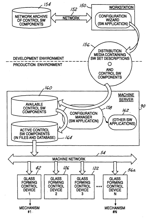
FIG. 4 illustrates one important advantage of the present invention, as
illustrated
in either FIG. 2 or FIGS. 3A-3B. That is, all control programming for all of
the glassware
forming system controllers can be entered, downloaded and monitored through a
single machine
sever 90. The system automatically manages all of the many control program
versions of the
several controllers in the glass container forming system. This avoids all of
the effort and errors
of manually updating each control program, and avoids the burden of shutting
down the entire
forming system when only a few of the control devices require an update. The
system also
manages the situation where updates to one of the control device programs
requires a
corresponding update to other device control programs. The system also
prevents the situation
in which a unique untested combination of control device program versions or
revision levels are
unintentionally deployed, potentially creating interaction problems. The
system also reduces the
12
CA 02495677 2005-02-15
WO 2004/026776 PCT/US2003/027548
amount of process down-time required to load and enable new control program
updates, and
simplifies reversion to previous control programs where needed.
Referring to FIG. 4, a work station 150 is illustrated as being connected by a
network 152 to an archive 154 ofpreviously employed control programming. A
control program
developer may employ suitable configuration wizard programming to compile a
set of control
programs, which may be stored on a suitable medium 156, such as a CD-ROM or
DVD, for
loading into machine server 90. As an alternative, operator work station 150
may comprise one
of the network user interfaces 114 (FIGS. 2 and 3A) connected to machine
server 90 by bus 54,
or may be connected to machine server 90 through bus 92, either directly or
through the Internet.
A configuration manager program 158 within machine server 90 loads the new
control
programming into amemory 160 ofavailable controlprograms. Configurationmanager
158 also
has access to a memory 162 of other control programs previously developed. If
the new control
programming is consistent with the hardware and controllers connected to
machine server 90,
configuration manager 158 may load the new control programming into a file 164
of active
control programming for down-loading to the appropriate controllers by means
of bus 54. In
addition to providing a central facility for storing, monitoring and down-
loading all control
programming, the system of the present invention has the advantage of reducing
the amount of
memory required in the various device controllers. In other words, it is not
necessary for servo
controller 42, servo ware handling controller 56, servo gob delivery
controller 58, etc. in FIGS.
2-3B to have sufficient memory to store a library of control programming
inasmuch as the control
programming required for immediate operation can be readily and rapidly
downloaded from
machine server 90. Furthermore, the ability or requirement for substantial
operator variation of
the control programming at the various controllers can be greatly reduced. A
graphic user
interface for all devices of the machine system may be provided at a single
station. There is
13
CA 02495677 2005-02-15
WO 2004/026776 PCT/US2003/027548
complete "top to bottom" communication of programming, parameters and status
information,
as well as time-critical control information. The invention also offers
advantages in improved
scalability and pricelperformance optimization, while having the capability
for supporting
additional peripheral devices as needed for further development.
FIGS. 5 and 6 illustrate two controller configurations for the various
electronic
controllers discussed in connection with FIGS.1-4. FIG. 5 illustrates a
controller configuration
170 without on-board non-volatile storage, while FIG. 6 illustrates a
controller configuration 172
with on-board non-volatile storage. Referring to FIG. 5, controller
configuration 170 is
connected to a host computer 176, such as machine server 90 in FIGS. 2-3A, by
means of a bus
177. Controller configuration 170 includes an application motherboard 178
having software
(SV~ readable application-specific indicia 180, such as a DIP switch. This
indicia identifies the
application for which the controller is intended, such as a servo ware
handling controller 5 6 (FIG.
2) for example. An interchangeable processor module 182 is removably connected
to board 178,
such as by means of a socket 184. Processor module 182 includes prestored
programming for
reading application identification indicia 180, communicating such indicia to
host computer 176
through network 177, and then downloading from the host computer control
programming
needed for operation in connection with the specific operating mechanisms for
which controller
configuration 170 is to be used. For example, if controller configuration 170
is to be used as a
servo ware handling controller 56 in FIG. 2, upon initial application of power
or at any other
suitable time for resetting control programming, host computer 176 (machine
server 90 in this
example) may download through network 177 (bus 54 in this example) all of the
control
programming needed for operation of machine conveyor drive 62, cross-conveyor
drive 64, radial
transfer drive 66 and lehr loader drive 68. On the other hand, if controller
configuration 170 in
FIG. 5 is intended for use as a machine valve controller 122 (FIG. 3A), and
application
14
CA 02495677 2005-02-15
WO 2004/026776 PCT/US2003/027548
identification indicia 180 so indicates, then machine valve controller 120
would obtain the
necessary control programming from machine server 90, and download the control
programming
to chute controller 136 by means of serial data bus 132 (FIG. 3A). In this
instance, network host
computer 176 in FIG. 5 would comprise machine valve controller 122 in FIG. 3A,
and network
175 would comprise serial bus 132.
Controller configuration 172 in FIG. 6 is particularly useful for controllers
connected to the next higher level controller 176 by a relatively slow network
connection 186.
Controller configuration 172 includes a processor module 188 removably and
interchangeably
mounted on a motherboard 190, such as by means of as socket 192. Processor
module 188
includes application-specific control programnvng in non-volatile storage 194,
and programming
196 for comparison of the programming stored in memory 194 to the application-
specific indicia
180 on motherboard 190. Upon initial application of power, application-
independent boot
software 198 causes processor identification software 196 to compare the
application-specific
programming in memory 194 with the application-identifying indicia 180 on the
motherboard to
1 S confirm that processor module 174 is suitable for that specific
application. For example, if
controller configuration 172 in FIG. 6 is employed as a chute controller 136
in FIG. 3A and the
processor module 188 fails, an operator would replace the failed processor
module with a new
processor module. However, inasmuch as all processor modules would generally
appear identical,
it is necessary to confirm that the new processor module 188 contains the
required programming
for use as a chute controller. This is accomplished by comparing the
application-specific
programming in memory 194 to the application-identifying indicia 180 before
initiating operation
of the chute control mechanism. If the comparison is satisfactory, then chute
control can begin.
However, if the comparison is not satisfactory, the operator would be advised
to replace the new
processor module with one appropriate for chute control, or alternatively to
download new
CA 02495677 2005-02-15
WO 2004/026776 PCT/US2003/027548
control programming from host computer 176 through network 1 ~6 (bus 54,
machine controller
122 and bus 132 in FIG. 3A) to configure the new processor module as one
suitable for chute
control.
There has thus been disclosed a glassware forming machine system, and more
particularly an electronic control system for controlling operation of
glassware forming and
transfer mechanisms, that fully satisfies all of the objects and aims
previously set forth. The
invention has been discussed in conjunction with a number of presently
preferred embodiments
thereof, and various modifications and variations have also been discussed.
Other modifications
and variations will readily suggest themselves to persons of ordinary skill in
the art. The
invention is intended to embrace these and all other modifications and
variations as fall within the
spirit and broad scope of the appended claims.
16