Language selection

Search

Patent 2495874 Summary

Third-party information liability

Some of the information on this Web page has been provided by external sources. The Government of Canada is not responsible for the accuracy, reliability or currency of the information supplied by external sources. Users wishing to rely upon this information should consult directly with the source of the information. Content provided by external sources is not subject to official languages, privacy and accessibility requirements.

Claims and Abstract availability

Any discrepancies in the text and image of the Claims and Abstract are due to differing posting times. Text of the Claims and Abstract are posted:

  • At the time the application is open to public inspection;
  • At the time of issue of the patent (grant).
(12) Patent: (11) CA 2495874
(54) English Title: INDUCTION FLUSH DEVICE
(54) French Title: DISPOSITIF DE CHASSE PAR INDUCTION
Status: Expired and beyond the Period of Reversal
Bibliographic Data
(51) International Patent Classification (IPC):
  • E3D 5/10 (2006.01)
  • E3D 11/13 (2006.01)
(72) Inventors :
  • OUYOUNG, CRYSTAL (Taiwan, Province of China)
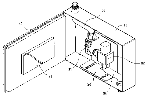
(73) Owners :
  • GLOBE UNION INDUSTRIAL CORP.
(71) Applicants :
  • GLOBE UNION INDUSTRIAL CORP. (China)
(74) Agent: OYEN WIGGS GREEN & MUTALA LLP
(74) Associate agent:
(45) Issued: 2007-11-06
(22) Filed Date: 2005-02-02
(41) Open to Public Inspection: 2006-08-02
Examination requested: 2005-04-08
Availability of licence: N/A
Dedicated to the Public: N/A
(25) Language of filing: English

Patent Cooperation Treaty (PCT): No

(30) Application Priority Data: None

Abstracts

English Abstract


The present invention discloses an induction flush device connecting
water supply and a toilet bowl. The induction flush device includes a tank,
a fixing board, a flush valve set and a panel. The panel is mounted on a side
of the tank. The flush valve set is mounted on the fixing board. The tank
forms a first guiding element thereon, and the fixing board forms a second
guiding element thereon for cooperating with the first guiding element,
thereby the fixing board is movable relative to the tank. The flush valve set
includes an anti-reverse valve, an electromagnetic valve, a flexible inlet
pipe for connecting with the water supply, and a flexible outlet pipe for
draining water to toilet bowl. The flush valve set is movable relative the
tank with the fixing board for repairing or replacement.


Claims

Note: Claims are shown in the official language in which they were submitted.

Claims:
1. An induction flush device, adapted for connecting water supply and a
toilet bowl, comprising:
a tank defining a chamber therein and an opening at a side thereof, and a
first guiding element being formed on the tank and accommodated in
the chamber;
a fixing board being accommodated in the chamber, and forming a second
guiding element thereon for cooperating with the first guiding element
thereby guiding the fixing board to transversely move relative to the
tank without displacement;
a flush valve set being mounted on the fixing board, and including an
anti-reverse valve, an electromagnetic valve, a flexible inlet pipe and a
flexible outlet pipe, wherein the anti-reverse valve and the
electromagnetic valve connecting with each other, the inlet pipe having
an end connecting with the anti-reverse valve and another end
connecting with the water supply, the outlet pipe having an end
connecting with the electromagnetic valve and another end connecting
with the toilet bowl; and
a panel being assembled on the opening of the tank, an induction sensor
being formed on the panel and electrically connecting with the
electromagnetic valve.
2. The induction flush device as claimed in claim 1, wherein the first
guiding element is stamped from a bottom of the tank and has two rows
of inverted L-shaped tracks which are opposing to each other.
3. The induction flush device as claimed in claim 2, wherein each row of
inverted L-shaped track of the first guiding element has two inverted
L-shaped blocks.
4. The induction flush device as claimed in claim 2, wherein the second
guiding element is integrally formed on the fixing board and has
L-shaped cross section for fitting with the first guiding element.
6

5. The induction flush device as claimed in claim 4, wherein the second
guiding element has two rows of L-shaped tracks which are opposing to
each other.
6. The induction flush device as claimed in claim 2, wherein a guiding slot
is defined in a bottom of the tank and between the inverted L-shaped
tracks of the first guiding element.
7. The induction flush device as claimed in claim 6, wherein a stop is
stamped downwardly from the fixing board and is slidable in the guiding
slot.
8. The induction flush device as claimed in claim 6, wherein the guiding
slot has an appropriate length lower than width of the tank.
9. The induction flush device as claimed in claim 1, wherein the induction
sensor is an infrared induction sensor.
10. The induction flush device as claimed in claim 1, wherein an
encryption lock is formed on the panel.
7

Description

Note: Descriptions are shown in the official language in which they were submitted.


CA 02495874 2005-02-02
SPECIFICATION
INDUCTION FLUSH DEVICE
BACKGROUND OF THE INVENTION
1. FIELD OF 'THE INVENTION
[0001) The present invention relates to an induction flush device, and
particularly to an induction flush device for flushing a toilet bowl.
2. RELATED ART
[0002] Induction flush devices are often used to automatically flush toilet
bowls, such as urinals and squat pans.
[0003] In prior art, wall-embedded induction flush device normally has a
tank embedded at a predetermined position on a wall, a chamber provided in
the tank, and a flush valve set. An inlet pipe is connected with an end of the
flush valve set for supplying water, and an outlet pipe is connected with
another end of the flush valve set for draining water to flush the toilet
bowl.
[0004] The flush valve set consists of an anti-reverse valve and an
electromagnetic valve. The anti-reverse valve connects with the inlet pipe.
The electromagnetic valve has an end connecting with the outlet pipe and
electrically connecting with an external infrared induction source.
[0005] The external infrared induction source is arranged at a cover of a
front side of the tank. The infrared induction source activates the
electromagnetic valve after use, and then water flows through the outlet pipe
to flush the water bowl.
[0006] Although the flush valve set automatically flush a toilet bowl, it
has to be removed from the chamber of the tank when the flush device needs
to be repaired. In order to reduce volume and manufacture cost, the chamber
of the tank has dimension nearly fit for size of the flush valve set. In a
whole,
i

CA 02495874 2005-02-02
the flush device is troublesome to be repaired, even some components
thereof cannot be repaired or replaced.
SUMMARY OF THE INVENTION
[0007] Accordingly, an object of the present invention is to provide an
induction flush device which is easily repaired and maintained.
[0008] To achieve the above object, the induction flush device of the
present invention comprises a tank, and a flush valve set mounted on a
fixing board. The tank defines a chamber therein. A first guiding element is
formed on the tank and accommodated in the chamber. The fixing board is
accommodated in the chamber, and forms a second guiding element thereon
for corresponding to the first guiding element thereby guiding the fixing
board to transversely move relative to the tank without displacement. The
flush valve set includes an anti-reverse valve, an electromagnetic valve, a
flexible inlet pipe and a flexible outlet pipe. The anti-reverse valve and the
electromagnetic valve connect with each other. The inlet pipe has an end
connecting with the anti-reverse valve and another end connecting with
water supply The outlet pipe has an end connecting with the
electromagnetic valve and another end connecting with a toilet bowl.
[0009] The first guiding element is stamped from a bottom of the tank
and has two rows of inverted L-shaped tracks which are opposing to each
other. The second guiding element is integrally formed on the fixing board
and has L-shaped cross section for fitting with the first guiding element.
BRIEF DESCRIPTION OF THE DRAWINGS
[0010] Fig. 1 is an assembled view of an induction flush device
according to the present invention.
2

CA 02495874 2005-02-02
[0011] Fig. 2 is another assembled view of Fig. 1.
[0012] Fig. 3 is an exploded view of the induction flush device of Fig. 1.
[0013] Fig. 4 is a front view of the induction flush device of Fig. 1.
[0014] Fig. 5 is an enlarged view of the encircled portion in Fig. 4.
[0015] Fig. 6 is a schematic cross-sectional view of the induction flush
device.
[0016] Fig. 7 conceptually shows a flush valve set of the induction flush
device is pulled out.
[0017] Fig. 8 conceptually shows the induction flush device mounted on
a urinal.
(0018] Fig. 9 conceptually shows the induction flush device mounted on
a squat pan.
DESCRIPTION OF THE PREFERRED EMBODIMENTS
[0019] With reference to Figs. 1 to 6, an induction flush device 1 in
accordance with the present invention comprises a tank 10, a fixing board 20,
a flush valve set 30 and a panel 40. The tank 10 is embedded onto a wall and
defines an opening (not labeled) at a side thereof and a chamber 11 therein.
A first guiding element 12 is integrally formed at a bottom of the tank 10
and is accommodated on the chamber 11. The first guiding element 12 has
inverted L-shaped cross section. In this embodiment, the first guiding
element 12 has two rows of inverted L-shaped tracks which are stamped
from a bottom of the tank 10 and are opposing to each other. Each row of
inverted L-shaped track of the first guiding element 12 has two inverted
L-shaped blocks. The fixing board 20 is accommodated in the chamber 11. A
second guiding element 21 is integrally formed on the fixing board 20 and
3

CA 02495874 2005-02-02
has L-shaped cross section for fitting with the first guiding element 12. The
second guiding element 21 has two rows of L-shaped tracks which are
opposing to each other for cooperating with the inverted L-shaped tracks of
the first guiding element 12. The fixing board 20 is transversely slidable
relative to the tank 10 along the first guiding element 12 without
displacement. A guiding slot 13 is defined in a bottom of the tank 10 and
between the inverted L-shaped tracks of the first guiding element 12. The
guiding slot 13 has appropriate length lower than width of the tank 10. A
stop 22 is stamped downwardly from the fining board 20 and is slidable in
the guiding slot 13 thereby resisting the first guiding element 12
disengagement from the second guiding element 21.
[0020] The flush valve set 30 is mounted on the fixing board 20 and
comprises an anti-reverse valve 31, an electromagnetic valve 32, an inlet
pipe 33 and an outlet pipe 34. The inlet valve 33 and the outlet valve 34 are
made of flexible material. The anti-reverse valve 31 and the electromagnetic
valve 32 are respectively fixed on the fixing board 20 and connect with each
other. The inlet pipe 33 has an end connecting with the anti-reverse valve 31,
and another end connecting with water supply (not shown). The outlet pipe
34 has an end connecting with the electromagnetic valve 32, and another
end connecting with a toilet bowl (not shown).
[0021] The panel 40 is mounted on the opening of the tank 10. An
induction sensor 41 is formed on the panel 40 and electrically connects with
the electromagnetic valve 32. In this embodiment, the induction sensor 41 is
an infrared induction sensor.
[0022] Further referring to Figs. 8 and 9, the induction flush device 1
may be assembled with a urinal 50 or a squat pan 60. The induction sensor
41 on the panel 40 activates the electromagnetic valve 32 when detecting
use of the urinal 50 or the squat pan 60. Meanwhile water flows through the
4

CA 02495874 2005-02-02
outlet pipe 34, and automatically flushes the toilet bowl of the urinal 50 or
the squat pan 60.
[0023] Combining with Figs. 2 through 7, when the flush valve set 30
needs to be repaired, a user may directly open the panel 40, and move the
fixing board 20 outward from the chamber 11 via the first guiding element
12 and the second guiding element 21. Correspondingly, the anti-reverse
valve 31 and the electromagnetic valve 32 move outside the tank 10 with the
fixing board 20, facilitating the user to replace or repair the anti-reverse
valve 31, the electromagnetic valve 32 and a filtering net (not shown). In
addition, the inlet pipe 33 and the outlet pipe 34 are flexible, and therefore
are free to extend or bend when the fixing board 20 moves relative to the
tank 10.
[0024] Referring to Figs. 8 and 9, an encryption lock 70 is formed on the
panel 40 for locking the panel 40 with the tank 10 after repairing, thereby
avoiding theft and destroying.
[0025] It is understood that the invention may be embodied in other
forms without departing from the spirit thereof. Thus, the present examples
and embodiments are to be considered in all respects as illustrative and not
restrictive, and the invention is not to be limited to the details given
herein.
s

Representative Drawing
A single figure which represents the drawing illustrating the invention.
Administrative Status

2024-08-01:As part of the Next Generation Patents (NGP) transition, the Canadian Patents Database (CPD) now contains a more detailed Event History, which replicates the Event Log of our new back-office solution.

Please note that "Inactive:" events refers to events no longer in use in our new back-office solution.

For a clearer understanding of the status of the application/patent presented on this page, the site Disclaimer , as well as the definitions for Patent , Event History , Maintenance Fee  and Payment History  should be consulted.

Event History

Description Date
Time Limit for Reversal Expired 2012-02-02
Letter Sent 2011-02-02
Grant by Issuance 2007-11-06
Inactive: Cover page published 2007-11-05
Inactive: Final fee received 2007-08-15
Pre-grant 2007-08-15
Notice of Allowance is Issued 2007-03-01
Letter Sent 2007-03-01
4 2007-03-01
Notice of Allowance is Issued 2007-03-01
Inactive: Approved for allowance (AFA) 2007-02-09
Application Published (Open to Public Inspection) 2006-08-02
Inactive: Cover page published 2006-08-01
Letter Sent 2005-06-15
Inactive: Single transfer 2005-05-04
Letter Sent 2005-05-03
Request for Examination Received 2005-04-08
Request for Examination Requirements Determined Compliant 2005-04-08
All Requirements for Examination Determined Compliant 2005-04-08
Inactive: First IPC assigned 2005-03-24
Inactive: IPC assigned 2005-03-24
Inactive: Courtesy letter - Evidence 2005-03-15
Inactive: Filing certificate - No RFE (English) 2005-03-09
Application Received - Regular National 2005-03-09

Abandonment History

There is no abandonment history.

Maintenance Fee

The last payment was received on 2007-01-12

Note : If the full payment has not been received on or before the date indicated, a further fee may be required which may be one of the following

  • the reinstatement fee;
  • the late payment fee; or
  • additional fee to reverse deemed expiry.

Patent fees are adjusted on the 1st of January every year. The amounts above are the current amounts if received by December 31 of the current year.
Please refer to the CIPO Patent Fees web page to see all current fee amounts.

Fee History

Fee Type Anniversary Year Due Date Paid Date
Application fee - standard 2005-02-02
Request for examination - standard 2005-04-08
Registration of a document 2005-05-04
MF (application, 2nd anniv.) - standard 02 2007-02-02 2007-01-12
Final fee - standard 2007-08-15
MF (patent, 3rd anniv.) - standard 2008-02-04 2007-12-28
MF (patent, 4th anniv.) - standard 2009-02-02 2008-12-24
MF (patent, 5th anniv.) - standard 2010-02-02 2010-01-05
Owners on Record

Note: Records showing the ownership history in alphabetical order.

Current Owners on Record
GLOBE UNION INDUSTRIAL CORP.
Past Owners on Record
CRYSTAL OUYOUNG
Past Owners that do not appear in the "Owners on Record" listing will appear in other documentation within the application.
Documents

To view selected files, please enter reCAPTCHA code :


To view images, click a link in the Document Description column (Temporarily unavailable). To download the documents, select one or more checkboxes in the first column and then click the "Download Selected in PDF format (Zip Archive)" or the "Download Selected as Single PDF" button.

List of published and non-published patent-specific documents on the CPD .

If you have any difficulty accessing content, you can call the Client Service Centre at 1-866-997-1936 or send them an e-mail at CIPO Client Service Centre.

({010=All Documents, 020=As Filed, 030=As Open to Public Inspection, 040=At Issuance, 050=Examination, 060=Incoming Correspondence, 070=Miscellaneous, 080=Outgoing Correspondence, 090=Payment})


Document
Description 
Date
(yyyy-mm-dd) 
Number of pages   Size of Image (KB) 
Description 2005-02-01 5 211
Claims 2005-02-01 2 67
Abstract 2005-02-01 1 22
Drawings 2005-02-01 6 93
Representative drawing 2006-07-24 1 18
Filing Certificate (English) 2005-03-08 1 158
Acknowledgement of Request for Examination 2005-05-02 1 176
Courtesy - Certificate of registration (related document(s)) 2005-06-14 1 114
Reminder of maintenance fee due 2006-10-02 1 110
Commissioner's Notice - Application Found Allowable 2007-02-28 1 162
Maintenance Fee Notice 2011-03-15 1 170
Correspondence 2005-03-08 1 26
Correspondence 2007-08-14 1 31
Fees 2010-01-04 1 33