Sélection de la langue

Search

Sommaire du brevet 2495874 

Énoncé de désistement de responsabilité concernant l'information provenant de tiers

Une partie des informations de ce site Web a été fournie par des sources externes. Le gouvernement du Canada n'assume aucune responsabilité concernant la précision, l'actualité ou la fiabilité des informations fournies par les sources externes. Les utilisateurs qui désirent employer cette information devraient consulter directement la source des informations. Le contenu fourni par les sources externes n'est pas assujetti aux exigences sur les langues officielles, la protection des renseignements personnels et l'accessibilité.

Disponibilité de l'Abrégé et des Revendications

L'apparition de différences dans le texte et l'image des Revendications et de l'Abrégé dépend du moment auquel le document est publié. Les textes des Revendications et de l'Abrégé sont affichés :

  • lorsque la demande peut être examinée par le public;
  • lorsque le brevet est émis (délivrance).
(12) Brevet: (11) CA 2495874
(54) Titre français: DISPOSITIF DE CHASSE PAR INDUCTION
(54) Titre anglais: INDUCTION FLUSH DEVICE
Statut: Périmé et au-delà du délai pour l’annulation
Données bibliographiques
(51) Classification internationale des brevets (CIB):
  • E3D 5/10 (2006.01)
  • E3D 11/13 (2006.01)
(72) Inventeurs :
  • OUYOUNG, CRYSTAL (Taïwan, Province de Chine)
(73) Titulaires :
  • GLOBE UNION INDUSTRIAL CORP.
(71) Demandeurs :
  • GLOBE UNION INDUSTRIAL CORP. (Chine)
(74) Agent: OYEN WIGGS GREEN & MUTALA LLP
(74) Co-agent:
(45) Délivré: 2007-11-06
(22) Date de dépôt: 2005-02-02
(41) Mise à la disponibilité du public: 2006-08-02
Requête d'examen: 2005-04-08
Licence disponible: S.O.
Cédé au domaine public: S.O.
(25) Langue des documents déposés: Anglais

Traité de coopération en matière de brevets (PCT): Non

(30) Données de priorité de la demande: S.O.

Abrégés

Abrégé anglais


The present invention discloses an induction flush device connecting
water supply and a toilet bowl. The induction flush device includes a tank,
a fixing board, a flush valve set and a panel. The panel is mounted on a side
of the tank. The flush valve set is mounted on the fixing board. The tank
forms a first guiding element thereon, and the fixing board forms a second
guiding element thereon for cooperating with the first guiding element,
thereby the fixing board is movable relative to the tank. The flush valve set
includes an anti-reverse valve, an electromagnetic valve, a flexible inlet
pipe for connecting with the water supply, and a flexible outlet pipe for
draining water to toilet bowl. The flush valve set is movable relative the
tank with the fixing board for repairing or replacement.

Revendications

Note : Les revendications sont présentées dans la langue officielle dans laquelle elles ont été soumises.


Claims:
1. An induction flush device, adapted for connecting water supply and a
toilet bowl, comprising:
a tank defining a chamber therein and an opening at a side thereof, and a
first guiding element being formed on the tank and accommodated in
the chamber;
a fixing board being accommodated in the chamber, and forming a second
guiding element thereon for cooperating with the first guiding element
thereby guiding the fixing board to transversely move relative to the
tank without displacement;
a flush valve set being mounted on the fixing board, and including an
anti-reverse valve, an electromagnetic valve, a flexible inlet pipe and a
flexible outlet pipe, wherein the anti-reverse valve and the
electromagnetic valve connecting with each other, the inlet pipe having
an end connecting with the anti-reverse valve and another end
connecting with the water supply, the outlet pipe having an end
connecting with the electromagnetic valve and another end connecting
with the toilet bowl; and
a panel being assembled on the opening of the tank, an induction sensor
being formed on the panel and electrically connecting with the
electromagnetic valve.
2. The induction flush device as claimed in claim 1, wherein the first
guiding element is stamped from a bottom of the tank and has two rows
of inverted L-shaped tracks which are opposing to each other.
3. The induction flush device as claimed in claim 2, wherein each row of
inverted L-shaped track of the first guiding element has two inverted
L-shaped blocks.
4. The induction flush device as claimed in claim 2, wherein the second
guiding element is integrally formed on the fixing board and has
L-shaped cross section for fitting with the first guiding element.
6

5. The induction flush device as claimed in claim 4, wherein the second
guiding element has two rows of L-shaped tracks which are opposing to
each other.
6. The induction flush device as claimed in claim 2, wherein a guiding slot
is defined in a bottom of the tank and between the inverted L-shaped
tracks of the first guiding element.
7. The induction flush device as claimed in claim 6, wherein a stop is
stamped downwardly from the fixing board and is slidable in the guiding
slot.
8. The induction flush device as claimed in claim 6, wherein the guiding
slot has an appropriate length lower than width of the tank.
9. The induction flush device as claimed in claim 1, wherein the induction
sensor is an infrared induction sensor.
10. The induction flush device as claimed in claim 1, wherein an
encryption lock is formed on the panel.
7

Description

Note : Les descriptions sont présentées dans la langue officielle dans laquelle elles ont été soumises.

CA 02495874 2005-02-02
SPECIFICATION
INDUCTION FLUSH DEVICE
BACKGROUND OF THE INVENTION
1. FIELD OF 'THE INVENTION
[0001) The present invention relates to an induction flush device, and
particularly to an induction flush device for flushing a toilet bowl.
2. RELATED ART
[0002] Induction flush devices are often used to automatically flush toilet
bowls, such as urinals and squat pans.
[0003] In prior art, wall-embedded induction flush device normally has a
tank embedded at a predetermined position on a wall, a chamber provided in
the tank, and a flush valve set. An inlet pipe is connected with an end of the
flush valve set for supplying water, and an outlet pipe is connected with
another end of the flush valve set for draining water to flush the toilet
bowl.
[0004] The flush valve set consists of an anti-reverse valve and an
electromagnetic valve. The anti-reverse valve connects with the inlet pipe.
The electromagnetic valve has an end connecting with the outlet pipe and
electrically connecting with an external infrared induction source.
[0005] The external infrared induction source is arranged at a cover of a
front side of the tank. The infrared induction source activates the
electromagnetic valve after use, and then water flows through the outlet pipe
to flush the water bowl.
[0006] Although the flush valve set automatically flush a toilet bowl, it
has to be removed from the chamber of the tank when the flush device needs
to be repaired. In order to reduce volume and manufacture cost, the chamber
of the tank has dimension nearly fit for size of the flush valve set. In a
whole,
i

CA 02495874 2005-02-02
the flush device is troublesome to be repaired, even some components
thereof cannot be repaired or replaced.
SUMMARY OF THE INVENTION
[0007] Accordingly, an object of the present invention is to provide an
induction flush device which is easily repaired and maintained.
[0008] To achieve the above object, the induction flush device of the
present invention comprises a tank, and a flush valve set mounted on a
fixing board. The tank defines a chamber therein. A first guiding element is
formed on the tank and accommodated in the chamber. The fixing board is
accommodated in the chamber, and forms a second guiding element thereon
for corresponding to the first guiding element thereby guiding the fixing
board to transversely move relative to the tank without displacement. The
flush valve set includes an anti-reverse valve, an electromagnetic valve, a
flexible inlet pipe and a flexible outlet pipe. The anti-reverse valve and the
electromagnetic valve connect with each other. The inlet pipe has an end
connecting with the anti-reverse valve and another end connecting with
water supply The outlet pipe has an end connecting with the
electromagnetic valve and another end connecting with a toilet bowl.
[0009] The first guiding element is stamped from a bottom of the tank
and has two rows of inverted L-shaped tracks which are opposing to each
other. The second guiding element is integrally formed on the fixing board
and has L-shaped cross section for fitting with the first guiding element.
BRIEF DESCRIPTION OF THE DRAWINGS
[0010] Fig. 1 is an assembled view of an induction flush device
according to the present invention.
2

CA 02495874 2005-02-02
[0011] Fig. 2 is another assembled view of Fig. 1.
[0012] Fig. 3 is an exploded view of the induction flush device of Fig. 1.
[0013] Fig. 4 is a front view of the induction flush device of Fig. 1.
[0014] Fig. 5 is an enlarged view of the encircled portion in Fig. 4.
[0015] Fig. 6 is a schematic cross-sectional view of the induction flush
device.
[0016] Fig. 7 conceptually shows a flush valve set of the induction flush
device is pulled out.
[0017] Fig. 8 conceptually shows the induction flush device mounted on
a urinal.
(0018] Fig. 9 conceptually shows the induction flush device mounted on
a squat pan.
DESCRIPTION OF THE PREFERRED EMBODIMENTS
[0019] With reference to Figs. 1 to 6, an induction flush device 1 in
accordance with the present invention comprises a tank 10, a fixing board 20,
a flush valve set 30 and a panel 40. The tank 10 is embedded onto a wall and
defines an opening (not labeled) at a side thereof and a chamber 11 therein.
A first guiding element 12 is integrally formed at a bottom of the tank 10
and is accommodated on the chamber 11. The first guiding element 12 has
inverted L-shaped cross section. In this embodiment, the first guiding
element 12 has two rows of inverted L-shaped tracks which are stamped
from a bottom of the tank 10 and are opposing to each other. Each row of
inverted L-shaped track of the first guiding element 12 has two inverted
L-shaped blocks. The fixing board 20 is accommodated in the chamber 11. A
second guiding element 21 is integrally formed on the fixing board 20 and
3

CA 02495874 2005-02-02
has L-shaped cross section for fitting with the first guiding element 12. The
second guiding element 21 has two rows of L-shaped tracks which are
opposing to each other for cooperating with the inverted L-shaped tracks of
the first guiding element 12. The fixing board 20 is transversely slidable
relative to the tank 10 along the first guiding element 12 without
displacement. A guiding slot 13 is defined in a bottom of the tank 10 and
between the inverted L-shaped tracks of the first guiding element 12. The
guiding slot 13 has appropriate length lower than width of the tank 10. A
stop 22 is stamped downwardly from the fining board 20 and is slidable in
the guiding slot 13 thereby resisting the first guiding element 12
disengagement from the second guiding element 21.
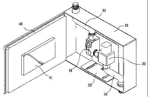
[0020] The flush valve set 30 is mounted on the fixing board 20 and
comprises an anti-reverse valve 31, an electromagnetic valve 32, an inlet
pipe 33 and an outlet pipe 34. The inlet valve 33 and the outlet valve 34 are
made of flexible material. The anti-reverse valve 31 and the electromagnetic
valve 32 are respectively fixed on the fixing board 20 and connect with each
other. The inlet pipe 33 has an end connecting with the anti-reverse valve 31,
and another end connecting with water supply (not shown). The outlet pipe
34 has an end connecting with the electromagnetic valve 32, and another
end connecting with a toilet bowl (not shown).
[0021] The panel 40 is mounted on the opening of the tank 10. An
induction sensor 41 is formed on the panel 40 and electrically connects with
the electromagnetic valve 32. In this embodiment, the induction sensor 41 is
an infrared induction sensor.
[0022] Further referring to Figs. 8 and 9, the induction flush device 1
may be assembled with a urinal 50 or a squat pan 60. The induction sensor
41 on the panel 40 activates the electromagnetic valve 32 when detecting
use of the urinal 50 or the squat pan 60. Meanwhile water flows through the
4

CA 02495874 2005-02-02
outlet pipe 34, and automatically flushes the toilet bowl of the urinal 50 or
the squat pan 60.
[0023] Combining with Figs. 2 through 7, when the flush valve set 30
needs to be repaired, a user may directly open the panel 40, and move the
fixing board 20 outward from the chamber 11 via the first guiding element
12 and the second guiding element 21. Correspondingly, the anti-reverse
valve 31 and the electromagnetic valve 32 move outside the tank 10 with the
fixing board 20, facilitating the user to replace or repair the anti-reverse
valve 31, the electromagnetic valve 32 and a filtering net (not shown). In
addition, the inlet pipe 33 and the outlet pipe 34 are flexible, and therefore
are free to extend or bend when the fixing board 20 moves relative to the
tank 10.
[0024] Referring to Figs. 8 and 9, an encryption lock 70 is formed on the
panel 40 for locking the panel 40 with the tank 10 after repairing, thereby
avoiding theft and destroying.
[0025] It is understood that the invention may be embodied in other
forms without departing from the spirit thereof. Thus, the present examples
and embodiments are to be considered in all respects as illustrative and not
restrictive, and the invention is not to be limited to the details given
herein.
s

Dessin représentatif
Une figure unique qui représente un dessin illustrant l'invention.
États administratifs

2024-08-01 : Dans le cadre de la transition vers les Brevets de nouvelle génération (BNG), la base de données sur les brevets canadiens (BDBC) contient désormais un Historique d'événement plus détaillé, qui reproduit le Journal des événements de notre nouvelle solution interne.

Veuillez noter que les événements débutant par « Inactive : » se réfèrent à des événements qui ne sont plus utilisés dans notre nouvelle solution interne.

Pour une meilleure compréhension de l'état de la demande ou brevet qui figure sur cette page, la rubrique Mise en garde , et les descriptions de Brevet , Historique d'événement , Taxes périodiques et Historique des paiements devraient être consultées.

Historique d'événement

Description Date
Le délai pour l'annulation est expiré 2012-02-02
Lettre envoyée 2011-02-02
Accordé par délivrance 2007-11-06
Inactive : Page couverture publiée 2007-11-05
Inactive : Taxe finale reçue 2007-08-15
Préoctroi 2007-08-15
Un avis d'acceptation est envoyé 2007-03-01
Lettre envoyée 2007-03-01
month 2007-03-01
Un avis d'acceptation est envoyé 2007-03-01
Inactive : Approuvée aux fins d'acceptation (AFA) 2007-02-09
Demande publiée (accessible au public) 2006-08-02
Inactive : Page couverture publiée 2006-08-01
Lettre envoyée 2005-06-15
Inactive : Transfert individuel 2005-05-04
Lettre envoyée 2005-05-03
Requête d'examen reçue 2005-04-08
Exigences pour une requête d'examen - jugée conforme 2005-04-08
Toutes les exigences pour l'examen - jugée conforme 2005-04-08
Inactive : CIB en 1re position 2005-03-24
Inactive : CIB attribuée 2005-03-24
Inactive : Lettre de courtoisie - Preuve 2005-03-15
Inactive : Certificat de dépôt - Sans RE (Anglais) 2005-03-09
Demande reçue - nationale ordinaire 2005-03-09

Historique d'abandonnement

Il n'y a pas d'historique d'abandonnement

Taxes périodiques

Le dernier paiement a été reçu le 2007-01-12

Avis : Si le paiement en totalité n'a pas été reçu au plus tard à la date indiquée, une taxe supplémentaire peut être imposée, soit une des taxes suivantes :

  • taxe de rétablissement ;
  • taxe pour paiement en souffrance ; ou
  • taxe additionnelle pour le renversement d'une péremption réputée.

Les taxes sur les brevets sont ajustées au 1er janvier de chaque année. Les montants ci-dessus sont les montants actuels s'ils sont reçus au plus tard le 31 décembre de l'année en cours.
Veuillez vous référer à la page web des taxes sur les brevets de l'OPIC pour voir tous les montants actuels des taxes.

Historique des taxes

Type de taxes Anniversaire Échéance Date payée
Taxe pour le dépôt - générale 2005-02-02
Requête d'examen - générale 2005-04-08
Enregistrement d'un document 2005-05-04
TM (demande, 2e anniv.) - générale 02 2007-02-02 2007-01-12
Taxe finale - générale 2007-08-15
TM (brevet, 3e anniv.) - générale 2008-02-04 2007-12-28
TM (brevet, 4e anniv.) - générale 2009-02-02 2008-12-24
TM (brevet, 5e anniv.) - générale 2010-02-02 2010-01-05
Titulaires au dossier

Les titulaires actuels et antérieures au dossier sont affichés en ordre alphabétique.

Titulaires actuels au dossier
GLOBE UNION INDUSTRIAL CORP.
Titulaires antérieures au dossier
CRYSTAL OUYOUNG
Les propriétaires antérieurs qui ne figurent pas dans la liste des « Propriétaires au dossier » apparaîtront dans d'autres documents au dossier.
Documents

Pour visionner les fichiers sélectionnés, entrer le code reCAPTCHA :


Pour visualiser une image, cliquer sur un lien dans la colonne description du document (Temporairement non-disponible). Pour télécharger l'image (les images), cliquer l'une ou plusieurs cases à cocher dans la première colonne et ensuite cliquer sur le bouton "Télécharger sélection en format PDF (archive Zip)" ou le bouton "Télécharger sélection (en un fichier PDF fusionné)".

Liste des documents de brevet publiés et non publiés sur la BDBC .

Si vous avez des difficultés à accéder au contenu, veuillez communiquer avec le Centre de services à la clientèle au 1-866-997-1936, ou envoyer un courriel au Centre de service à la clientèle de l'OPIC.

({010=Tous les documents, 020=Au moment du dépôt, 030=Au moment de la mise à la disponibilité du public, 040=À la délivrance, 050=Examen, 060=Correspondance reçue, 070=Divers, 080=Correspondance envoyée, 090=Paiement})


Description du
Document 
Date
(aaaa-mm-jj) 
Nombre de pages   Taille de l'image (Ko) 
Description 2005-02-01 5 211
Revendications 2005-02-01 2 67
Abrégé 2005-02-01 1 22
Dessins 2005-02-01 6 93
Dessin représentatif 2006-07-24 1 18
Certificat de dépôt (anglais) 2005-03-08 1 158
Accusé de réception de la requête d'examen 2005-05-02 1 176
Courtoisie - Certificat d'enregistrement (document(s) connexe(s)) 2005-06-14 1 114
Rappel de taxe de maintien due 2006-10-02 1 110
Avis du commissaire - Demande jugée acceptable 2007-02-28 1 162
Avis concernant la taxe de maintien 2011-03-15 1 170
Correspondance 2005-03-08 1 26
Correspondance 2007-08-14 1 31
Taxes 2010-01-04 1 33