Language selection

Search

Patent 2495976 Summary

Third-party information liability

Some of the information on this Web page has been provided by external sources. The Government of Canada is not responsible for the accuracy, reliability or currency of the information supplied by external sources. Users wishing to rely upon this information should consult directly with the source of the information. Content provided by external sources is not subject to official languages, privacy and accessibility requirements.

Claims and Abstract availability

Any discrepancies in the text and image of the Claims and Abstract are due to differing posting times. Text of the Claims and Abstract are posted:

  • At the time the application is open to public inspection;
  • At the time of issue of the patent (grant).
(12) Patent: (11) CA 2495976
(54) English Title: FLUID FLOW CONTROL BARRIER
(54) French Title: BARRIERE DE CONTROLE DE DEBIT DE LIQUIDE
Status: Granted
Bibliographic Data
Abstracts

English Abstract


A barrier primarily intended as a silt dam includes a tubular body with a
planar
skirt extending outwardly from one side thereof for anchoring the barrier to
the
ground. A helical spring in the body biases the body to an elongated,
extended, use
position. The body can be collapsed and held in a compact condition for
storing or
transporting of the barrier by straps on the ends of the body and releasably
interengageable buckles on the straps


French Abstract

Une barrière destinée à servir principalement de barrage de limon comprend un corps tubulaire avec une jupe plane s'étendant vers l'extérieur d'un côté pour ancrer la barrière au sol. Un ressort hélicoïdal dans le corps sollicite ce corps pour qu'il prenne une position d'utilisation sortie allongée. Ce corps peut être rentré et maintenu à l'état compact pour ranger ou transporter la barrière au moyen de courroies, aux extrémités du corps tubulaire, et de boucles qui s'engagent mutuellement de manière libérable sur les courroies.

Claims

Note: Claims are shown in the official language in which they were submitted.


CLAIMS:
1. A barrier for controlling flow of fluid comprising a flexible, tubular,
water-
permeable body means having a first end and a second end, the body means being
extensible to define an elongated tube and collapsible between said first and
second ends;
spring means in said body means biasing the body means to an extended
condition; and
planar skirt means extending outwardly from one side of said body means for
anchoring
the barrier to a surface.

2. The barrier of claim 1 further comprising at least one connector means on
each of
said first and second end; the connector means for connecting said first end
to said second
end for releasably retaining the body means in a collapsed condition, in which
said spring
means is compressed, and for connecting said body means to a similar body
means,
whereby a plurality of body means can be connected end-to-end to form an
elongated dam.
3. The barrier of claim 2, wherein said connector means each include two
releasably
interlockable members, including a first member attached to said first end,
and a second
member attached to said second end.

4. The barrier of any one of claims 2 or 3, further comprising at least one
strap means
on each of said first and second end, the strap means disposed between said
connector
means and said first end, and between said connector means and said second
end.

5. The barrier of any one of claims 2 or 3, further comprising a plurality of
spaced
apart, complementary strap means on each of said first and second ends, the
strap means
disposed between said connector means and said first end, and between said
connector
means and said second end.

6. The barrier of any one of claims 2 or 3, further comprising three
complementary
strap means spaced equidistant apart on each of said first and second ends,
the strap means
disposed between said connector means and said first end, and between said
connector
means and said second end.


7. The barrier of any one of claims 1 to 6, wherein said body means is formed
of a
water permeable material.

8. The barrier of claims 1 to 6, wherein said body means is formed of a
material
selected from the group consisting of polyethylene, polyester, burlap,
tarpaulin and a
geotextile.

9. The barrier of claim 1 to 6, wherein said body means is formed of a woven
polypropylene fabric permeable to water and impermeable to contaminants
including oil,
tar, soil, sand and gravel.

10. The barrier of any one of claims 1 to 9, wherein said skirt means is
formed of the
same material as said body means.

11. A method of installing a barrier for controlling flow of fluid comprising
providing
the barrier of any one of claims 1 to 10, placing the barrier in a selected
position,
stretching the skirt means out, and anchoring the skirt means.

12. The method of claim 11, wherein the skirt means is anchored using one or
more
spikes.

13. The method of any one of claims 11 or 12 further comprising connecting two
or
more barriers end-to-end.

14. The method of any one of claims 11 to 13 wherein the selected position is
on a
slope.

15. The method of claim 14 wherein the skirt means is stretched out in an
uphill
direction.

16. Use of the barrier of any one of claims 1 to 10 as a dam for slowing
water.
17. Use of the barrier of any one of claims 1 to 10 as a dam for filtering
water.
6


18. Use of the barrier of any one of claims 1 to 10 as a dam for slowing water
on a
slope.

7

Description

Note: Descriptions are shown in the official language in which they were submitted.


CA 02495976 2011-06-02

FLUID FLOW CONTROL BARRIER
BACKGROUND OF THE INVENTION
FIELD OF THE INVENTION

This invention relates to a portable barrier for controlling the flow of
fluid.
It will be appreciated from the following that the barrier of the present
invention
can be used as a silt filter or as a dam. The primary function of the barrier
is energy
dissipation. Silt-containing water flowing against the barrier is slowed down,
thus
dissipating the energy of the fluid and allowing silt to settle out of the
suspension.
DISCUSSION OF THE PRIOR ART
Erosion and silt or sediment control barriers are disclosed by a large number
of Canadian and US patents and applications including CA 2,381,234 (Bradley),
and
US 5,158,395 (Holmberg), US 5,951,202 (Brown), US 6,109,835 (Grabhorn), US
6,547,493 (Spangler et al) and US 2003/0010968 (Hendrickson). While existing
barriers of the type described in the literature are more or less effective,
they tend to
be somewhat bulky and/or difficult to use.
GENERAL DESCRIPTION OF THE INVENTION
The object of the present invention is to provide a relatively simple,
portable
barrier for use, inter alia, for slowing and/or filtering silt laden water
which is
lightweight, collapsible and compact when collapsed.
Accordingly, the present invention relates to a barrier for controlling the
flow of
fluid comprising flexible, tubular body means having a first end and a second
end, the
body means being extensible to define an elongated tube and collapsible
between
said first and second ends; spring means in said body means biasing the


1


CA 02495976 2011-06-02

body means to an extended condition; at least one strap means on each said
first
and second end of the body means; and connector means on said strap means for
connecting said first end of the body means to said second end for releasably
retaining the body means in a collapsed condition, in which said spring means
is
compressed, and for connecting said first end of the body means to the second
end
of a similar body means, whereby a plurality of body means can be connected
end-
to-end to form an elongated dam.

BRIEF DESCRIPTION OF THE DRAWINGS
The invention is described below in greater detail with reference to the
accompanying drawings, which illustrate a preferred embodiment of the barrier,
and
wherein:
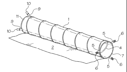
Figure 1 is a schematic, isometric view of a barrier in accordance with the
invention;
Figure 2 is a partly sectioned isometric view of one end of the barrier of
Fig. 1;
Figure 3 is an isometric view of the barrier of Fig. 1 in the collapsed
condition;
and
Figure 4 is an isometric view of complete and partial barriers interconnected
end-to-end to form a dam.
DESCRIPTION OF THE PREFERRED EMBODIMENT
With reference to Figs. 1 to 3, the barrier of the present invention includes
an
elongated, tubular body 1, and a skirt 2 attached thereto and extending
tangentially
therefrom. Both the body 1 and the skirt 2 are permeable or impermeable to
water.
The body 1 and the skirt 2 are preferably formed of a material which is at
least partly
permeable to water, but impermeable to contaminants such as oil, tar, gravel,
soil

2


CA 02495976 2005-02-02

and sand. Suitable materials include plastics such as polyethylene and
polyesters,
burlap and tarpaulin. A preferred material for the body 1 and the skirt 2 is a
so-
called geotextile or geomembrane such as the woven polypropylene fabric
available
from Amoco Fabrics and Fiber Company under the trade-mark PROLEX 2006.

According to the manufacturer, such fabrics are stabilized to resist
degradation due
to UV exposure, resistant to common soil chemicals, mildew and insects, and is
non-
biodegradable.

A helical spring 3 is mounted in the body 1 and extends the entire length
thereof. The spring 3 is retained in the body 1 by a strip 4 of fabric, which
is sewn to
the interior of the body 1 to cover the spring 3 and retain it in position.
The spring 3

biases the body 1 to the open, expanded, use condition shown in Fig. 1, but
permits
compression of the body 1 to the collapsed condition shown in Fig. 3. The
skirt 2 is
sewn to the side of the body 1 and extends tangentially therefrom in the use
position
(Figs. 1 and 3) to complete the barrier.

Straps 5 with buckle members 6 on the free ends thereof are attached to one
end 7 of the tubular body 1. Straps 9 with buckle members 10 complementary to
parts 6 are attached to the other end 11 of the body 1. Preferably the straps
are
equidistant apart at 120 to each other. The members 6 and 10 are separable,
plastic, and releasably interlockable, i.e. the buckles 12 formed by
connecting the

members 6 and 10 together are of the type shown, inter alia, in Fig. 10 of the
Bakker
et al US Patent No. 4,171,555.

For storage or transportation, the body 1 is collapsed by pressing the ends 7
and 11 towards each other. The buckle members 6 and 10 are interconnected to
releasably hold the body 1 in the collapsed condition. Upon reaching a
workplace,
3


CA 02495976 2005-02-02

the buckles 12 are opened to permit the body to return to the extended, use
condition. The skirt 2 is stretched out horizontally and the barrier is placed
in
position on a slope (not shown) with the skirt 2 extending in an uphill
direction. The
skirt 2 is anchored in position using spikes or ground anchors (not shown). A

plurality of barriers are connected end-to-end using the buckles 12 to form a
dam.
When the body 1 and the skirt 2 are formed of a porous material, which permits
the
restricted flow of water, upon striking the dam, the water slows down
permitting
settling of the silt on the skirt 2 and against the body 1. The accumulation
of silt on
the skirt 2, further anchors the barriers in position.

4

Representative Drawing
A single figure which represents the drawing illustrating the invention.
Administrative Status

For a clearer understanding of the status of the application/patent presented on this page, the site Disclaimer , as well as the definitions for Patent , Administrative Status , Maintenance Fee  and Payment History  should be consulted.

Administrative Status

Title Date
Forecasted Issue Date 2012-08-21
(22) Filed 2005-02-02
(41) Open to Public Inspection 2006-08-02
Examination Requested 2009-07-22
(45) Issued 2012-08-21

Abandonment History

Abandonment Date Reason Reinstatement Date
2007-02-02 FAILURE TO PAY APPLICATION MAINTENANCE FEE 2007-04-17

Maintenance Fee

Last Payment of $229.50 was received on 2021-02-17


 Upcoming maintenance fee amounts

Description Date Amount
Next Payment if small entity fee 2023-02-02 $253.00
Next Payment if standard fee 2023-02-02 $624.00

Note : If the full payment has not been received on or before the date indicated, a further fee may be required which may be one of the following

  • the reinstatement fee;
  • the late payment fee; or
  • additional fee to reverse deemed expiry.

Patent fees are adjusted on the 1st of January every year. The amounts above are the current amounts if received by December 31 of the current year.
Please refer to the CIPO Patent Fees web page to see all current fee amounts.

Payment History

Fee Type Anniversary Year Due Date Amount Paid Paid Date
Application Fee $200.00 2005-02-02
Registration of a document - section 124 $100.00 2005-06-10
Reinstatement: Failure to Pay Application Maintenance Fees $200.00 2007-04-17
Maintenance Fee - Application - New Act 2 2007-02-02 $50.00 2007-04-17
Maintenance Fee - Application - New Act 3 2008-02-04 $50.00 2008-01-03
Maintenance Fee - Application - New Act 4 2009-02-02 $50.00 2008-12-17
Request for Examination $400.00 2009-07-22
Maintenance Fee - Application - New Act 5 2010-02-02 $200.00 2010-01-21
Advance an application for a patent out of its routine order $500.00 2010-11-02
Maintenance Fee - Application - New Act 6 2011-02-02 $200.00 2010-11-16
Maintenance Fee - Application - New Act 7 2012-02-02 $200.00 2012-01-24
Final Fee $150.00 2012-06-11
Maintenance Fee - Patent - New Act 8 2013-02-04 $100.00 2012-11-08
Maintenance Fee - Patent - New Act 9 2014-02-03 $100.00 2013-11-22
Maintenance Fee - Patent - New Act 10 2015-02-02 $125.00 2014-12-15
Maintenance Fee - Patent - New Act 11 2016-02-02 $325.00 2016-03-31
Maintenance Fee - Patent - New Act 12 2017-02-02 $125.00 2016-03-31
Maintenance Fee - Patent - New Act 13 2018-02-02 $125.00 2016-03-31
Maintenance Fee - Patent - New Act 14 2019-02-04 $125.00 2016-03-31
Maintenance Fee - Patent - New Act 15 2020-02-03 $225.00 2016-03-31
Maintenance Fee - Patent - New Act 16 2021-02-02 $225.00 2016-03-31
Maintenance Fee - Patent - New Act 17 2022-02-02 $229.50 2021-02-17
Owners on Record

Note: Records showing the ownership history in alphabetical order.

Current Owners on Record
BMP SUPPLIES INC.
Past Owners on Record
LINDEMULDER, JIM
Past Owners that do not appear in the "Owners on Record" listing will appear in other documentation within the application.
Documents

To view selected files, please enter reCAPTCHA code :


To view images, click a link in the Document Description column. To download the documents, select one or more checkboxes in the first column and then click the "Download Selected in PDF format (Zip Archive)" or the "Download Selected as Single PDF" button.

List of published and non-published patent-specific documents on the CPD .

If you have any difficulty accessing content, you can call the Client Service Centre at 1-866-997-1936 or send them an e-mail at CIPO Client Service Centre.


Document
Description 
Date
(yyyy-mm-dd) 
Number of pages   Size of Image (KB) 
Abstract 2011-06-02 1 12
Description 2011-06-02 4 132
Claims 2011-06-02 2 70
Abstract 2005-02-02 1 12
Description 2005-02-02 4 131
Claims 2005-02-02 2 50
Drawings 2005-02-02 3 50
Representative Drawing 2006-07-25 1 11
Cover Page 2006-07-25 1 34
Claims 2011-12-09 3 73
Cover Page 2012-07-27 1 36
Correspondence 2010-02-22 1 15
Assignment 2005-06-10 2 42
Correspondence 2005-03-10 1 25
Assignment 2005-02-02 2 60
Fees 2007-04-17 1 29
Fees 2008-01-03 1 24
Fees 2010-01-27 1 31
Fees 2010-01-15 1 127
Fees 2008-12-17 1 23
Prosecution-Amendment 2009-07-22 1 22
Correspondence 2009-12-09 3 91
Correspondence 2010-01-20 1 14
Correspondence 2010-01-20 1 20
Correspondence 2010-02-12 1 22
Prosecution-Amendment 2011-09-12 3 128
Prosecution-Amendment 2010-11-02 1 36
Prosecution-Amendment 2010-11-09 1 12
Prosecution-Amendment 2010-12-21 2 85
Prosecution-Amendment 2011-06-02 9 381
Prosecution-Amendment 2011-12-09 8 382
Correspondence 2012-06-11 1 29
Fees 2014-12-15 1 33
Fees 2016-03-31 1 33