Note: Descriptions are shown in the official language in which they were submitted.
CA 02496081 2005-02-02
ACCELERATED WEATHERING TEST APPARATUS
WITH FULL SPECTRUM CALIBRATION, MONITORING AND CONTROL
Field of the Invention
[0001] The present invention is directed to an accelerated
weathering test apparatus and, more particularly, to an indoor accelerated
weathering test apparatus which uses a full spectrum power distribution
("SPD") of an artificial light source for calibration, monitoring and control
of the
apparatus.
Background of the Invention
[0002] Indoor accelerated weathering test apparatus are known to
test the accelerated aging characteristics of painted surfaces, fabrics,
plastic
sheeting and other materials. Such testing is accomplished by exposing the
materials to be tested to high intensity radiation from an artificial light
source
that approximates sunlight, under conditions of controlled and sometimes high
temperature and/or humidity.
[0003] In a natural outdoor environment, heat, light and moisture
combine to synergistically cause optical, mechanical and chemical changes in
products which are exposed to such outdoor weathering conditions. Generally,
the test apparatus of the present invention and the prior art can be used to
obtain such weathering data on an accelerated time basis, to permit product
manufacturers to gain information as to how their products will stand up to
weathering conditions over the months or years.
1
CA 02496081 2005-02-02
[0004] Typically, an accelerated weathering test apparatus may use
air which circulates through the system to control the temperature of samples
being tested, so that they are not underheated or overheated by heater or
radiation source which may be present, typically a high-intensity plasma lamp
such as a xenon lamp. It is desirable for the samples being tested to be
exposed to precisely predetermined conditions, to permit more accurate
comparison between various testing runs and so that the weathering
conditions provided by the test apparatus can be accurately predetermined and
thus recreated when desired for comparison of various samples over the years.
[0005] In known accelerated weathering test apparatus, a rotatable
rack for carrying the samples to be tested surrounds a light source, often a
xenon lamp, which emits irradiation having a substantial ultraviolet
component. The rack is rotated typically about one revolution per minute, to
avoid any systematic differences of positioning of the samples in the system.
Also, the typical level of irradiation imposed on the samples is approximately
one SUN, which is defined in The Society of Automotive Engineers J-1885
weathering testing method to be 0.55 watt per square meter at 340 nanometers
ultraviolet radiation.
[0006] Other known accelerated weathering test apparatus further
accelerate the aging of materials by exposing such materials to an irradiance
level that is higher than one SUN, for example two SUNs (or about 1.1 watts
per square meter in accordance with the previous definition). It has been
noted
that at such higher light intensities, the irregularity of light irradiance
around
2
CA 02496081 2005-02-02
the rack at the area of the samples becomes larger, contributing to sample
temperature variations. As a result, the samples may be affected in their
testing program by these variables.
[0007]
Other known accelerated weathering test apparatus monitor
and control irradiance of the light source only at three discrete points of
the
light source SPD. Namely, prior art test apparatus measure light source
irradiance only at 340 nanometers ("nm"), 420 nm and 300-400 nm.
Measurements are made a fixed band-pass optical filter and associated closed
loop feedback electronics. Standard test methods specify one of the three
control points and are not user selectable. These known test monitoring and
controlling methods are particularly disadvantageous for several reasons. For
example, test specimen materials currently under development are sensitive to,
-
age or degrade as a result of exposure to irradiance from the light source at
specific wavelengths other than the set standard. In current instruments it is
not possible to control the wavelength of maximum or critical sensitivity for
specific materials. Further, the SPD of the light source changes as the light
source and inner and outer filters age over time. Again, with a static
irradiance
control wavelength the optimum accelerated weathering cannot be achieved.
As a result, the reliability of the test specimens is affected in their
respective
testing programs by these variables.
[0008]
Calibration of known accelerated weathering test apparatus
is also cumbersome, time consuming and introduces considerable margin for
error into the test results for a client accelerated weathering test
apparatus.
3
CA 02496081 2005-02-02
Prior art calibration schemes are directed to the steps of: calibrating a
spectroradiometer from a 1000 watt Tungsten calibration standard; measuring
a standard factory light source with the spectroradiometer and assigning a
calibration value; calibrating a factory accelerated weathering test apparatus
radiometer by operation with the standard factory light source and adjusting
radiometer gain in accordance with the calibration value; operating factory
accelerated weathering test apparatus with a client standard light source and
assigning calibration values based on radiometer readings; and operating a
client accelerated weathering test apparatus with the client standard light
source and adjusting radiometer gain of client test apparatus to match
calibration values. As a result, the possibilities for uncertainties produced
by
known prior art apparatus is sizeable and vast. Even if the factory executes
each of its steps flawlessly, there are still opportunities for the client to
make
errors. Accordingly, the test specimens are affected in their respective
testing
program by these variables.
[0009] One known weathering apparatus includes a radiation
measuring device. A portion of radiation used for testing is guided to the
measuring device. The guided radiation is spectrally dispersed so that
intensity and/or dosage may be measured by selected diodes at discrete points
on the SPD. The radiation detector consists of an array of photodiodes
assigned to monitor preselected discrete wave lengths.
[0010] Another prior art apparatus for exposing photographic film
includes a source of illumination operated at a constant correlated color
4
CA 02496081 2005-02-02
temperature and intensity. A spectroradiometer takes in light images of the
spectrum from 380 nm to 740 nm onto a linear array of thirty-two photodiodes.
As a result, the spectral radio meter provides thirty-two signals indicative
of the
intensity of light in each of the thirty-two uniform which bands together
extending from 380 nm to 740 nm. The value of the color temperatures and
illuminance for the thirty-two wavelengths nominally at the middle of each of
the thirty-two bands are derived from the thirty-two signals from the sensors.
From these values, the luminosity of radiant power in color temperature can be
derived. The spectroradiometer generates signals indicative of the illuminance
and the correlated color temperature, which are transmitted to an automatic
control which tests the signals to determine if they are within tolerance. The
automatic control and a stepping motor are responsive to signals from the
spectroradiometer for adjusting the intensity of a light emitted by the
generator. In order to keep color temperature and radiation constant, the
distance between the light source and a spherical mirror is altered to adjust
the intensity.
[0011]
Yet another prior art weathering instrument includes a light
intensity monitoring and adjusting device including a light guide made of
optical fiber, a light receiving section and an adjusting section in a
recording
instrument. The light guide is configured as a flexible tube containing a
bundle of optical fibers which is trisected. One end of the light guide is
directed toward the lamp and the other, tri-sected, end is connected to the
light
receiving section. A lens in the light receiving section for each part of the
CA 02496081 2005-02-02
bundle of fibers directs the light to respective light receiving elements,
such as
photoelectric tubes, through respective filters.
The three light receiving
elements measure the composition of light at the three fixed, discrete points.
One sensor is used to control the intensity of the light and the other two
sensors are used to compare what set points to judge the quality of the
spectrum.
[0012] Still another prior art test apparatus describes a
methodology for calibration of a radiometric device with radiation at various
intensity levels and spectral distributions. The calibration system includes a
light source which emits a beam of light in the direction of a radiometric
device
for calibrating and/or testing a device. A portion of the light beam is
intercepted by the device and another portion of the light beam is intercepted
by a detector which is a photodiode. The detector is operated with spectral
filtering to view one or more specific spectral bands of interest in the
radiation
outputted by the light source. The detector provides an output current, via a
switch, to a control unit for operating an intensity controller to energize
the
light source. The current of a single photodetector is asserted to be an
accurate predictor of the light intensity within the filtered band for
characterizing a linear relationship between photodetector current and
intensity.
[0013] Therefore, there exists a need in the art for an accelerated
weathering test apparatus which overcomes the disadvantages of the prior art,
namely: monitoring and controlling a test apparatus with respect to fixed,
6
CA 02496081 2005-02-02
discrete portions of a light source SPD, inability to calibrate, monitor and
control the test apparatus based on the full SPD of a light source, inability
to
calibrate, monitor and control a test apparatus light source with respect to a
user-selectable discrete wavelength, i.e. wavelengths or wavelength range
inability to test material sensitivity to different parts of the full SPD,
inability to
calibrate a test apparatus over a full SPD for a given light source with
respect
to accepted professional certified standards and inability to monitor changes
to
the full SPD of a given light source as such light source or associated
filters
degrade with time.
[0014] By the present invention, improvements are provided which
increase the accuracy of the calibration, monitoring and control of the test
apparatus of this invention. In that the test apparatus can be used to provide
accurately predetermined conditions which are substantially predictable and
invariant throughout a run and from run to run.
The Brief Description of the Drawings
[0015] The invention may be best understood by reference to the
following description taken in conjunction with the accompanying drawings, in
the several figures of which life reference numerals identify like elements.
[0016] FIG. 1 is a perspective view of a prior art accelerated
weathering test apparatus.
[0017] FIG. 2A is an elevation view of an accelerated weathering
test
apparatus in accordance with one embodiment of the present invention.
7
CA 02496081 2005-02-02
=
[0018] FIG. 2B is an elevation view of an accelerated weathering
test
apparatus in accordance with another embodiment of the present invention.
[0019] FIG. 3A is a flow chart directed to the steps for calibration
of
an accelerated weathering test apparatus in accordance with one embodiment
of the present invention.
[0020] FIG. 3B is a flow chart directed to additional steps for
calibration of the accelerated weathering test apparatus of FIG. 3A.
[0021] FIG. 3C is a flow chart directed to additional calibration
steps for the accelerated weathering test apparatus of FIG. 3A.
[0022] FIG. 3D is a flow chart directed to additional calibration
steps for the accelerated weathering test apparatus of FIG. 3A.
[0023] FIG. 3E is a flow chart directed to additional calibration
steps for the accelerated weathering test apparatus of FIG. 3A.
[0024] FIG. 4 is a flow chart directed to a step of filtering in
FIG. 3D.
[0025] FIG. 5 is a graphical representation of a portion of the SPD
for a calibration light source monitored by a traceable spectroradiometer.
[0026] FIG. 6 is a graphical representation of a second group of
measurements from a second full SPD for the calibration light source operated
in a client accelerated weathering test apparatus.
[0027] FIG. 7 is a graphical representation of the first full SPD of
the calibration light source after filtering.
8
CA 02496081 2005-02-02
[0028] FIG. 8 is a graphical representation of the second full SPD
of
the calibration light source of FIG. 6 after filtering.
[0029] FIG. 9A is a graphical representation of an initial aligning
step for the first and second filtered data sets.
[0030] FIG. 9B is a graphical representation of a subsequent step of
aligning the first and second filtered data sets.
[0031] FIG. 10 is a graphical representation of a system response
factor of the client accelerated weathering test apparatus.
[0032] FIG. 11 is a graphical representation of the full SPD of the
client accelerated weathering test apparatus after calibration.
[0033] FIG. 12 is a flow chart directed to the steps in accordance
with one embodiment of the present invention for operating the calibrated
client accelerated weathering test apparatus.
Detailed Description of a Preferred Embodiment of the Invention
[0034] Briefly, in one embodiment of the present invention, a
method for calibrating an irradiance level control in a client accelerated
weathering test apparatus includes the following steps: installing a
calibration
light source in a factory accelerated weathering test apparatus; operating the
factory accelerated weathering test apparatus at a fixed power level as
determined by a first calibrated device; collecting a first full SPD of the
calibration light source; generating a first group of measurements from the
first
full SPD; storing the first group of measurements as a first data set;
installing
the calibration light source in a client accelerated weathering test
apparatus;
9
CA 02496081 2005-02-02
operating the client accelerated weathering test apparatus at the fixed power
level as determined by the second calibrated device; collecting a second full
SPD for the calibration light source; generating a second group of
measurements from the second full SPD; storing the second group of
measurements as a second data set; filtering the first and second data sets;
aligning the first and second filtered data sets; and determining a system
response factor of the client accelerated weathering test apparatus in order
to
calibrate the irradiance level control of the client accelerated weathering
test
apparatus.
[0035] In another embodiment of the present invention, a method of
exposing test specimens in a client accelerated weathering test apparatus to
an
accurate preselected level of irradiance includes the following steps:
determining a power level for generating a preselected level of irradiance
from a
light source based upon a type of light source filter assembly, a first data
set
for a calibrated light source and a desired irradiance level set point at a
control
wavelength from the light source; determining a measured irradiance level from
the light source based upon a second data set for the light source adjusted by
a
system response factor; comparing the power level against the measured
irradiance level at the control wavelength; generating a light source power
control signal; and repeating the above steps at preselected intervals for a
desired period of time.
[0036] And yet another embodiment of the present invention is
directed to an accelerated weathering test apparatus includes a test chamber.
CA 02496081 2012-11-05
A test specimen mount for supporting test specimens is disposed in the test
chamber. A light source is also disposed within the test chamber for generator
irradiance. A controller generates a light source power control signal based
upon the plurality of inputs. A power source is responsive to the light source
power control signal for outputting power to the light source. A
spectroradiometer collects a full SPD of the light source then generates a
data
set representative of the full SPD in order to output the data set to the
controller as one of the plurality of inputs.
[0037]
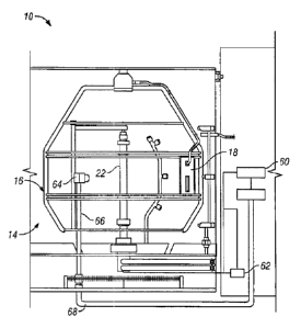
Referring to FIG. 1, a weathering testing device 10 is shown,
which comprises a housing 12 defining an upper chamber 14 in which a rack
16 resides, comprising a roughly spherical array of stainless steel struts, to
which test specimens 18 may be attached in a manner substantially
equidistant from a central light source 22, which may be a xenon, fluorescent,
metal halide, mercury or tungsten lamp. This arrangement is similar to that
disclosed in U.S. Pat. Nos. 5,503,032 and 5,854,433.
[0038] At
the bottom of upper chamber 14 a circular arrangement
of apertures 26 are provided, plus a conical baffle 24, to assist in directing
air
passing through apertures 26 along test samples 18 carried on the rack.
[0039] A
conventional resistance-type heater element 30 may be
positioned under apertures 26 and the partition that carries them, for helping
to control the temperature of the air surrounding the specimens 18. The
fitting
of the light source 22 may be in accordance with U.S. Pat. No. 5,226,318
11
CA 02496081 2012-11-05
including both electrical and water flow conduits for providing the same to
the
light source 22.
[0040] Rack 16 is carried by a first support member or shaft 34
which extends through the top wall 36 of the upper chamber 14. Thus, the
connections of various electronic devices carried on rack 16 may pass with
shaft 34 through top wall 36 to a microprocessor 38 that is carried in the
weathering testing system above top wall 36, in a manner that is safely spaced
from both the flowing water and the high electric currents and voltages used
with respect to the light source 22.
[0041] A motor M is positioned above top wall 36, which rotates
shaft 34 and rack 16. Test rack 16 may carry a black panel temperature
sensor 40, which is a sensor particularly adapted to sense the temperature
directly imparted by the radiation from the light source. A dry bulb sensor
may
also be provided at a position more remote from light source 22 to monitor air
temperature. Also, a direct percentage relative humidity sensor may be
provided. Each of these can provide signal data to microprocessor 38.
[0042] The top wall also defines wall apertures which represent the
inlet of a circulatory plenum 46 that circulates air, driven by blower 28,
from
top to the bottom of chamber 14 and through apertures 26, as propelled by
blower 28.
[0043] Within plenum 46 is a variably openable cooling air supply
vent 48, having a movable damper 50, and comprising air inlet 48b and air
outlet 48a. The position of the damper 50 can be controlled by a control
12
CA 02496081 2005-02-02
member 51 which is, in turn, controlled by the microprocessor 38 in a
conventional manner.
[0044] Rack water spray or atomizer unit 52 is also provided in
upper chamber 14, along with a specimen water sprayer atomizer unit 53,
provided for added specific spraying of the specimens when that is desired.
[0045] Further details with respect to weathering test machine 10
may be as disclosed in the previously cited U.S. Pat. Nos. 5,503,032 and
5,854,433.
[0046] Referring to FIGS. 2A and 2B, an elevation view of an
accelerated weathering test apparatus 10 in accordance with embodiments of
the present invention are illustrated. It will be recognized by those of skill
in
the art that the structural and functional aspects of the embodiments of the
present invention are as set forth above with respect to such aspects
described
and explained in connection with FIG. 1, except for the further details set
forth
below. Accordingly, further description of this embodiment will be directed to
only those structural and functional aspects of the present embodiment and
such aspects of the embodiment described in FIG. 1 necessary to support and
enable the description of the embodiments in FIGS. 2A and 2B. It is within the
teachings of the present invention that the structural and functional aspects
of
the apparatus described with respect to FIG. 1 and the references incorporated
herein shall apply and enable any of the embodiments of the present invention.
[0047] The accelerated weathering test apparatus 10 of these
embodiments include an upper or test chamber 14, a rack or test specimen
13
CA 02496081 2005-02-02
mount 16 for supporting test specimens 18 in the test chamber 14. A light
source 22 is disposed within the test chamber 14 for generating irradiance in
the test chamber 14. A controller 60 generates a light source power control
signal based upon a plurality of inputs, as will be discussed below. A power
source 62 responsive to the light source power control signal for outputting
power to the light source 22. An input device 64 is disposed within the test
chamber 14 for direct interface with irradiance from the light source 22 in
order to facilitate and enable monitoring of the full SPD of the light source
22.
A data set representative of the full SPD is generated and outputted to the
controller 60 as one of the plurality of inputs.
[0048] The controller 60 determines a power level for generating a
preselected level of irradiance from the light source 22 based upon a
plurality
of inputs. Preferably, the plurality of inputs include at least the following;
a
type of light source filter assembly; a calibrated light source data set (as
described below); and a desired irradiance level set point for a control
wavelength from the light source 22. It is within the teachings of the present
invention that additional inputs to the controller 60 may be desired and used
to facilitate and enable more precise control over the power level.
[0049] The controller further determines a measured irradiance
level from the light source 22 based upon the data set for the light source 22
adjusted by a system response factor, each described in more detail below. It
will be recognized by those of skill in the art that the term "data set" as
used in
connection with the embodiment described with respect to FIGS. 2A and 2B is
14
CA 02496081 2005-02-02
equivalent to the term "second data set" as used hereafter and may be used
interchangeably therewith. The controller 60 compares the power level and the
measured irradiance level, generates a light source power control signal which
is outputted to the power source 62 and repeats the above steps at preselected
intervals for a desired period of time. Thereby, precise and accurate
operation
of the accelerated weathering test apparatus that overcomes the disadvantages
of the prior art may be accomplished.
[0050] Preferably, the controller 60 includes a processing unit and
memory that stores programming instructions that, when used by the
processing unit, causes the controller to function to: determine a power level
for generating a preselected level of irradiance from a light source based
upon a
type of light source filter assembly, a calibrated light source data set and a
desired irradiance level set point at a control wavelength from the light
source;
determine a measured irradiance level from the light source based upon the
data set for the light source adjusted by a system response factor; compare
the
power level and the measured irradiance level; generate a light source power
control signal; and repeat the above steps at preselected intervals for a
desired
period of time.
[0051] The processor in this invention may be, but not limited to,
a
single processor, plurality of processors, a DSP, a microprocessor, ASIC,
state
machine, or any other implementation capable of processing and executing
software. The term processor should not be construed to refer exclusively to
hardware capable of executing software, and may implicitly include DSP
CA 02496081 2005-02-02
hardware, ROM for storing software, RAM, and any other volatile or non-
volatile storage medium.
[0052] The memory in this invention may be, but not limited to, a
single memory, a plurality of memory locations, shared memory, CD, DVD,
ROM, RAM, EEPROM, optical storage, microcode or any other non-volatile
storage capable of storing digital data for use by the processor.
[0053] The power source 62 is the same as used in connection with
the embodiment described in FIG. 1. However, operation in connection with
the controller 60 now enables the power source 62 to be adjusted such that a
reliably consistent irradiance level is provided during any test.
[0054] The input device may be a spectroradiometer, a receiving
optic device or any other suitable input device that is disposed within the
test
chamber 14 for direct interface with irradiance from the light source 22 and
operatively communicates with a spectroradiometer. In FIG. 2A, the input
device 64 is disposed on a stand 66 within the circumference of the test
specimen mount 16. In FIG. 2B, the input device 64 is mounted on the test
specimen mount 16 as would a test specimen in a test specimen plane defined
by such test specimen supported by the test specimen mount or rack.
[0055] In the event the input device 69 is the receiving optic
device
or other suitable device other than a spectroradiometer disposed within the
test
chamber 14 for direct interface with irradiance from the light source 22 as
shown in either of FIGS. 2A or 2B, a lightivave guide facilitates and is
useful for
channeling the light from the light source to the spectroradiometer which is
16
CA 02496081 2005-02-02
disposed remote from the test chamber 14 or within and not exposed to direct
irradiance.
[0056]
Generally the spectroradiometer may be, but not limited to,
any suitable device having a monochrometer and a photosensitive device or a
diode array. Preferably, the spectroradiometer is a linear charged coupled
device that can be calibrated to National Institute of Standards and Testing
("NIST") standards. For example, one suitable spectroradiometer useful in
connection with the present invention may be model number OL 754-C from
Optronic Laboratories of Orlando, Florida. Other suitable spectroradiometers
which facilitate or enable the functional aspects of the present invention may
also be used.
[0057]
As described above, the light source 22 may be a lamp
selected from the group consisting of xenon, fluorescent, metal halide,
mercury
and tungsten lamps. It will be recognized by those of skill in the art that
other
suitable light sources known or later discovered may be used to provide the
desired results.
[0058]
FIGS. 3A, 3B, 3C, 3D, 3E and 4 illustrate flow charts
directed to various steps for calibration of an irradiance level control in a
client
accelerated weathering test apparatus in accordance with the various
embodiments of the present invention. Initially, the factory accelerating
weathering test apparatus must be calibrated.
More particularly, the
spectroradiometer used in connection with the factory accelerated weathering
test apparatus must be calibrated in accordance with known standards in
17
CA 02496081 2005-02-02
order to provide the precision and accuracy in the later steps of the
calibration
procedure of the present invention. A known standard test method for
calibration of a spectroradiometer using a standard source of irradiance is
set
forth in the American Society for Testing and Materials Publication G138,
which is fully incorporated herein by reference. A standard source of
irradiance or calibration light source may be a lamp selected from the group
consisting of xenon, fluorescent, metal halide, mercury and tungsten lamps. It
will be recognized by those of skill in the at that other suitable calibration
light
sources known or later discovered may be used to provide the desired results.
[0059]
Briefly, the steps illustrated in FIG. 3A are directed to this
initial setup of the factory accelerated weathering test apparatus. In step
300,
a NIST-traceable light source is mounted in the factory accelerated weathering
test apparatus in accordance with known standards. In step 302, a first
calibrated device is used to set a fixed power level for the NIST-traceable
light
source. For example, the first calibrated device may be a wattmeter or other
suitable power level control device. Preferably, the first calibrated device
and
other calibrated devices mentioned herein are configured as NIST-traceable
wattmeters. In step 304, the factory accelerated weathering test apparatus is
operated in accordance with the above steps such that the spectroradiometer
operatively coupled to the factory accelerated weathering test apparatus
measures a full SPD of the NIST-traceable light source. As a result, in step
306, the factory accelerated weathering test apparatus is calibrated to the
NIST-traceable light source.
18
CA 02496081 2005-02-02
[0060]
FIG. 3B is a flow chart directed to the next additional steps
for calibrating the irradiance level control in the client accelerated
weathering
test apparatus. In step 308, a calibration light source is mounted in the
factory accelerated weathering test apparatus. In step 310, the first
calibrated
device is used to set the fixed power level for operating the factory
accelerated
weathering test apparatus. In step 312, during operation of the factory
accelerated weathering test apparatus, the NIST-traceable calibrated
spectroradiometer collects a first full SPD of the calibration light source.
In
step 314, the NIST-traceable spectroradiometer generates a first group of
measurements from the first full SPD. In step 316, the first group of
measurements are stored as a first data set. Further with respect to the first
and/or groups of measurements, the equally spaced intervals are
approximately 1 nanometer, less than 1 nanometer or greater than 1
nanometer. FIG. 5 is a graphical representation of a portion of the first full
SPD for the calibration light source as collected by the NIST-traceable
spectroradiometer in accordance with one embodiment of the present
invention. The first data set is useful to facilitate or enable calibration of
the
client accelerated weathering test apparatus and the operation thereof as will
be described below. It will be recognized by those of skill in the art that
the
units along the X-axis are wavelengths as measured in nanometers and the
units along the Y-axis are irradiance as measured in watts per square meter.
Each measurement of the first group of measurements is expressed as a first
19
CA 02496081 2005-02-02
irradiance amplitude for each of a plurality of discreet wavelengths in
equally
spaced intervals over the first full SPD.
[0061] The first data set is preferably captured in a data store or
memory which may be, but is not limited to, a single memory, plurality of
memory locations, shared memory, CD, DVD, ROM, RAM, EPROM, optical
storage, macrocode or any other non-volatile storage capable of storing
digital
data for use by a processor. More preferably, the first data set is captured
in a
portable data store or memory which can be transmitted, forwarded or
distributed with the calibration light source for use in connection with a
client
accelerated weathering test apparatus.
[0062] FIG. 3C is a flow chart directed to additional calibration
steps for calibrating the irradiance level control in the client accelerated
weathering test apparatus. In step 318, the calibration light source is
installed
in the client accelerated weathering test apparatus. In step 320, a second
calibrated device is used to set a fixed power level to operate the client
accelerated weathering test apparatus. As discussed above, the second
calibrated device may be any such suitable device and preferably a NIST-
traceable wattmeter. In step 322, a spectroradiometer operatively coupled to
the client accelerated weathering test apparatus collects a second full SPD
for
the calibration light source. In step 324, a second group of measurements
from the second full SPD is generated. In step 326, the second group of
measurements is stored as a second data set. FIG. 6 is a graphical
representation of the second group of measurements from the second full SPD
CA 02496081 2005-02-02
for the calibration light source operated in the client accelerated weathering
test apparatus in accordance with one embodiment of the present invention. It
will be recognized by those of skill in the art that the units along the X-
axis are
pixels (of the linear charge coupled device in this embodiment) and the units
along the Y-axis are counts (observed by the pixels). In other words, in this
embodiment of the present invention, a linear charge coupled device is used as
a spectroradiometer and each sensor element or pixel observes the number of
counts which are representative of the intensity of a certain wavelength of
the
second full SPD. The second data set is preferably stored in a memory or data
source as "memory" has been defined and used herein.
[0063]
FIG. 3D is a flow chart directed to additional calibration
steps for calibrating the irradiance level control in a client accelerated
weathering test apparatus. In step 328, the first data set is filtered. FIG. 7
is a
graphical representation of the first full SPD of the calibration light source
of
FIG. 5 or first data set after filtering in accordance with one embodiment of
the
present invention. In step 330, the second data set is filtered. FIG. 8 is a
graphical representation of the second full SPD of the calibration light
source of
FIG. 6 or second data set after filtering in accordance with one embodiment of
the present invention. Generally, each of the filtering steps uses an
algorithm
to isolate and identify source peaks of the first and second full SPDs.
Preferably, the step of filtering uses the algorithm:
= xi - [1/16 x E (4- 1 j-3 1) = x(i _
21
CA 02496081 2005-02-02
where y = one of the filtered data sets;
x = the other of the filtered data sets;
i = Index digit,
to isolate and identify source peaks of the first and second full SPDs.
[0064]
The algorithm generally is an indexing equation for
mathematical curve smoothing.
Preferably, the algorithm subtracts a
mathematically smoothed curve from the original curve isolate and identify
source peaks of each of the first and second full SPDs.
[0065]
In step 332, the first and second filtered data sets are
aligned. FIG. 4 is a flow chart directed to the step of aligning discussed in
step
332. FIG. 9A is a graphical representation of an initial aligning step for the
first and second filtered data sets. It will be reorganized by those of skill
in the
art that the units along the x-axis are wavelength per pixel and along the y-
axis
as source peaks. Initially, there is a difference or error delta between the
wavelength (first data set) and pixel (second data set) data. In step 334, the
second data set is shifted by a pre-selected increment. In step 336, the first
data set is interpolated in increments of the derived error delta or offset,
by a
wavelength offset. In step 338, an error between the shifted second data set
and the interpolated first data set is determined. In step 340, the error is
compared against a pre-selected threshold. In the event the error is greater
than the pre-selected threshold, the step of aligning the first and second
filtered data sets is repeated in accordance with the above steps. Preferably,
the pre-selected threshold is approximately in the range the provides
acceptable accuracy. It will be recognized by one of skill in the art that the
22
CA 02496081 2005-02-02
threshold is dependant on the light source and the spectroradiometer. In step
342, if the error is less than the pre-selected threshold, an expression for
an
optimum shifted second data set and interpolated first data set is determined
and the normalization or alignment of respective data sets.
[0066]
FIG. 9B is a graphical representation of a subsequent step of
aligning the first and second filtered data sets after the error is less than
threshold and the optimum shift and interpolation expression has been
determined. Again, it will be recognized that the units along the x- and y-
axis
are the same as FIG. 9a.
[0067]
FIG. 3E is a flow chart directed to additional calibration
steps for calibrating an irradiance level control in a client accelerated
weathering test apparatus. In step 344, a system response factor of the client
accelerated weathering test apparatus is determined in order to calibrate the
irradiance level control of the client accelerated weathering test apparatus.
The
system response factor is based on the filtered first and second data sets and
the optimum shift and interpolation expression. As a result, the system
response factor represents a discrete wavelength specific ratio of the output
signal to the input stimulus, as described herein. The steps in determining
the
system response factor includes finding the ratio of the output to the input
for
each wavelength over a full SPD.
[0068]
FIG. 10 is a graphical representation of a system response
factor of the client accelerated weathering test apparatus in accordance with
one embodiment of the present invention. It will be recognized by those of
skill
23
CA 02496081 2005-02-02
in the art that the system response factor is expressed as a signal output
amplitude of each of a plurality of discreet wavelengths of a full SPD with
respect to the client accelerated weathering test apparatus. In other words,
as
will be discussed in more detail below, the system response factor is useful
to
adjust the irradiance level control for a particular client accelerated
weathering
text apparatus to a NIST traceable level.
[0069] FIG. 11 is a graphical representation of a full SPD
generated
by the client accelerated weathering test apparatus after calibration. It will
be
recognized by those of skill in the art that the graphical representation of
the
full SPD of FIG. 11 is substantially identical to the graphical representation
of
the full SPD of FIG. 5 indicating that the irradiance level control in the
client
accelerating weathering test apparatus is now calibrated to a NIST-traceable
level. As a result, accurate and predictable results may be obtained from the
client accelerated weathering test apparatus.
[0070] In one embodiment of the present invention, the step of
collecting the first full SPD, is facilitated by a NIST-traceable
spectroradiometer
used in connection with the factory accelerated weathering test apparatus.
Such spectroradiometer may include a monochrometer and a photo-sensitive
device and may be selected from the group consisting of a linear charged
coupled device and a diode array.
[0071] It is within the teachings of the present invention that the
step of collecting the second full SPD is facilitated by a spectroradiometer
used
in connection with the client accelerated weathering test apparatus. Such
24
CA 02496081 2005-02-02
spectroradiometer preferably may include a monochrometer and a photo-
sensitive device which may be selected from the group consisting of a linear
charged coupled device and a diode array.
[0072] FIG. 12 of the flow chart is directed to the steps in
accordance with one embodiment of the present invention for operating the
calibrated client accelerated weathering test apparatus to expose test
specimens therein to an accurate pre-selected level of irradiance. In step
408,
a power level for generating a pre-selected level of irradiance from a light
source
is determined. The process of determining the power level is based on
preceding steps 400-406. Namely, a type of light source filter assembly is
inputted in step 400, a desired irradiance level set point for a control
wavelength from the light source is inputted in steps 402 and 404, and a first
data set for a calibrated light source is retrieved from memory in step 406.
In
step 410, the client accelerated weathering test apparatus is activated in
order
to begin exposing test specimens to irradiance from the light source.
[0073] A measured irradiance level from the light source is observed
in step 418 based upon the preceding steps. Namely, the actual irradiance
from the light source is collected and conditioned in step 412, a second data
set is generated in step 414 and the second data set is adjusted by a system
response factor in step 416.
[0074] In step 420, the power level and the measured irradiance
level at the control wavelength are compared. In the event the measured
irradiance level does not correspond with the irradiance level set point, an
CA 02496081 2005-02-02
adjusted light source power control signal is generated in step 424 and the
process resets back to step 410. In the event the measured irradiance level
corresponds with the irradiance level set point and the desired time period
for
exposure is not expired in step 426, then the process of this embodiment of
the
present invention pauses for an interval in step 428 and, after the pause,
resets the process to step 410. In the event the desired time period for
exposure is expired in step 426, the exposure of the test specimens in the
client accelerated weathering test apparatus ends in step 430.
[0075] It is within the teachings of the present invention that the
control wavelength may be a range of wavelengths or a specified range of
wavelengths and that such may be used to determine photometric output. For
example, a LUX value may be deremined from any full SPD derived in
accordance with the present invention appliced to a mathematical function
known to those of skill in the art. In one embodiment of the present
invention,
this may be characterized by the raw data weighted with respect to a human
eye, i.e. photopic response.
[0076] In one embodiment of the present invention, the first data
set includes a first group of measurements from a first full SPD where each
measurement of the first group of measurements is expressed as a first
irradiance amplitude for each of a plurality of discreet wavelengths in
equally
spaced intervals over the first full SPD.
Preferably, the first group of
measurements is enabled by a NIST-traceable spectroradiometer.
26
CA 02496081 2012-11-05
[0077] Further in one embodiment of the present invention, the
second data set includes a second group of measurements from a second full
SPD where each measurement of the second group of measurements is
expressed as a number of counts for each sensor element. The second group of
measurements is enabled by a NIST-traceable spectroradiometer and such
spectroradiometer may be a linear charged coupled device or any other suitable
device.
[0078] Various modifications and changes may be made by those
skilled in the art without departing from the scope of the
invention, as defined by the depending claims. For example, the apparatus
may be configured to operate with the advantages described herein with
respect to other suitable light sources, calibration light sources and
spectroradiometers.
27