Note: Descriptions are shown in the official language in which they were submitted.
CA 02496115 2005-02-08
SANDBAG WALL SYSTEM WITH
SANDBAGS HAVING A WAIST PORTION
Technical Field of the Invention
The invention pertains to sandbag wall systems for use in erosion
control, flood protection, coastal protection, slope stabilization and
similar applications,
Background of the Invention
In the art of erosion control, flood protection, coastal protection, slope
stabilization and the like, it is known to build stable and effective walls
of sandbags, preferably using interconnecting plates to connect the bags
together and stabilize the wall. See, for example, international patent
publication WO 00/61880 (Kim), dated October 19, 2000. The
interconnecting members attach the sandbags in adjacent courses to each
other so as to stabilize and strengthen the sandbag wall structure,
permitting the construction of permanent (and temporary) retaining wall
structures and ones that may be higher and steeper than conventional
sandbag retaining walls. The interconnecting members are plates
having projections on both sides that protrude into horizontally and
vertically adjacent sandbags.
Canadian patent application No. 2,426,836 (Kim) published October 25,
2004 discloses a retaining wall structure which uses interconnecting
members as described in WO 00/61880, in which sandbags are also
placed in a position extending from the wall face into the backfill behind
the wall at spaced-apart positions along selected courses, in order to
stabilize the wall face and the backfill. The present invention is directed
to a form of sandbag which is particularly useful in the construction of
such walls.
CA 02496115 2005-02-08
-2-
Summar~r of the Invention
The invention provides a sandbag having a waist portion. The waist has
a smaller cross-sectional area than the remainder of the bag, forming a
bag shape that has greater resistance to movement when embedded in
the backfill material supported by a sandbag wall, thus serving a soil
and anchoring function in relation to the wall and backfill. In use, the
sandbags with a waist portion are positioned so as to extend from the
wall face into the backfill, thus stabilizing the wall and the backfill. The
invention permits the construction of sandbag walls that are near vertical
as well as sloped.
In this specification, "fill material" means any material that is suitable
for use in bags in the construction of walls, including sand, soil, gravel,
dry mix concrete (which hardens after wetting and curing) and mixtures
thereof, including fill material with seeds for vegetation. The term
"sandbag" as used in this specification means a bag containing any "fil:l
material . " For further clarity, the term is not limited to a bag in which.
the fill material is sand. The term "wall" as used herein in relation to
structures made of sandbags includes any array of sandbags that is
suitable for the purpose of erosion control (for example along
shorelines, riverbanks, etc.), flood control, retaining or stabilizing
slopes or embankments, noise barriers, landscaping, and for similar
applications.
Brief Description of the Drawings
Figure 1 is a perspective view of a sandbag having a waist according to
one embodiment of the invention;
CA 02496115 2005-02-08
-3-
Figure 2 is a perspective view of a sandbag having two waists;
Figure 3 is a cross-sectional side view of a retaining wall structure
according to a further embodiment of the invention; and
Figure 4 is a cross-sectional plan view of the wall of Figure 3.
Detailed Description of the Preferred Embodiments
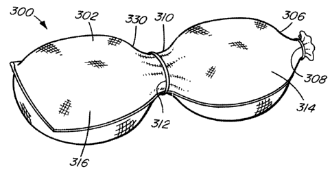
Referring to Figure 1, sandbag 300 has a bag wall 302, a closed bottom
304 and a top edge 306 which is closed with a tie 308, holding fill
material in the bag. The bag has waist 310.
The "waist" of a bag, as that term is used herein, means a portion of the
bag that has a smaller cross-sectional area in a plane perpendicular to a
longitudinal axis of the bag (i.e an axis of running between the top and
bottom of the bag) than a cross-sectional area of the bag in parallel
planes that are between the waist and the bottom of the bag and between
the waist and the top edge of the bag (apart from such planes through
another waist, in the case of a bag having two or more waists) . The
waist 310 is maintained by a tie 312 surrounding it. The waist 310
effectively divides the sandbag 300 into two sections 314, 316.
In other embodiments of the sandbag, there can be multiple waits, for
example two, three or more. Such additional waits enhance the
resistance to movement of the sandbag and therefore its soil anchoring
effect. By way of illustration, Figure 2 shows an embodiment of the
sandbag having two waists. Bag 301 has an upper waist 309 encircled
by tie 313 and lower waist 311 encircled by tie 315.
CA 02496115 2005-02-08
-4-
Referring to Figures 3 and 4, a retaining wall structure 320 according to
the invention is constructed on ground 322 and comprises a plurality of.
courses 324 of conventional sandbags 316, forming a wall face 318.
Backfill 326 is compacted behind and supported by sandbags 316.
At selected, longitudinally-spaced positions along selected, vertically-
spaced courses, sandbags 300 are placed in the courses 324 so as to
extend from the wall face into the backfill 326. Within a given course,
such extending sandbags 300 may be positioned, for example, between
every second and third conventional sandbags, or at such other spacing
as is appropriate for effective stabilization of the wall face in a
particular application. Likewise, the extending sandbags 300 may be
positioned at selected levels during the construction of a wall, for
example at every third course, or as required for a particular
application. It will be understood that extending sandbags 300 can be of
any desired and practical length, to extend into the backfill as far as
required for a given application. Sandbags 300 may accordingly be
longer and smaller in cross-section than conventional sandbags 316, if
desired.
Interconnecting members 328 are used in the construction of the
retaining wall 320. Preferably, the interconnecting members are of the
types described in WO 00/61880. The interconnecting members 328
are placed over horizontally-adjacent sandbags in a course to attach
them together and, at the same time, to attach vertically adjacent courses
together.
It will apparent that the extending sandbags 300, because they extend
into the backfill 326, anchor the face of the wall to the backfill
supported by the wall. This anchoring effect of the extending sandbags
300 is enhanced by the bag waist 310. Backfill 326 surrounds the bag
CA 02496115 2005-02-08
-5-
300 and the shoulders 330 of the bottom section 316 of the sandbag
press against the surrounding fill and resist movement of the bag 300 in
the direction of the wall face.
As will be apparent to those skilled in the art in the light of the
foregoing disclosure, many alterations and modifications are possible in
the practice of this invention without departing from the scope thereof.
Accordingly, the scope of the invention is to be construed in accordance
with the substance defined by the following claims.