Note: Descriptions are shown in the official language in which they were submitted.
CA 02496158 2005-02-18
WO 2004/018328 PCT/US2003/026199
METHOD AND APPARATUS FOR TRANSPORTING AND
STORING TIRES
FIELD OF THE INVENTION
[0001 ] The present invention relates to methods and devices for transporting
and storing tires
such as those used on cars and trucks.
BACKGROUND OF THE INVENTION
[0002] Tires are commonly encountered objects. They are used on a variety of
vehicles, such
as automobiles, and frequently need to be changed. Tires come in a variety of
shapes, sizes and
specifications, and may differ substantially depending on their particular
design. Snow tires, for
example, are specially configured for use in winter driving conditions. These
tires are, however,
not particularly desirable when primary driving occurs during warmer
spring/summer months.
As such, the owner of a vehicle may wish to own several sets of different
tires and utilize specific
tires designed for particular purposes.
[0003] When not used, tires require storage. For example, while not in use
during summer
months, snow tires must be stored. In addition, tires may need to be
transported, such as to or
from a tire service center or from one area of a car garage to another. The
transport and storage
of tires are inconvenient, difficult and dirty tasks, but the need to perform
these tasks arises in
a variety of situations.
[0004] The transport and storage of tires is difficult for a number of
reasons. One reason is
that, especially when mounted to a supporting wheel, automobile and truck
tires can be rather
heavy and awkward to handle. Another problem is that tires are round. While
the opportunity
exists to roll tires in order to transport them, they may quickly pick up
speed and roll out of
control. The fact that tires can easily roll also makes their storage
difficult, as they may roll about
a garage.
[0005] Tires which are stored also pose safety problems. Stacked tires are
often unstable and
may tip over, causing damage or injury.
CA 02496158 2005-02-18
WO 2004/018328 PCT/US2003/026199
[0006] Another problem is that tires are often very dirty. Snow tires used
throughout the
winter may be covered with mud, brake dust, grease, oil, salt or other
material. This material
may rub off onto a person or surrounding objects.
[0007] Another problem is that tires can break down or be damaged when exposed
to sunlight,
weather, chemicals, or other destructive elements.
[0008] A method and apparatus which provides for convenient, effective and
easy transport
and storage of tires is desired.
SUMMARY OF THE INVENTION
[0009] The invention is a method and apparatus for transporting and storing
one or more tires.
In one embodiment of the invention, the apparatus includes at least one
container for housing at
least one tire.
[0010] In one embodiment, the container comprises first section and second
section. When
connected, the first and second sections define an interior space within which
one or more tires
may be located. In one form, the first and second sections include a generally
circular base
portion with a wall extending upwardly from the periphery of the base portion,
thus defining a
generally cylindrical element. When connected, the walls of the first and
second sections
overlap.
[0011 ] The container may include means for connecting the first and second
sections. In one
embodiment, the means for connecting includes at least one projection located
on an inner
surface of the wall of one section and at least one depression located on the
outer surface of the
other section. In one embodiment, the projection comprises a generally annular
rib and the
depression comprises a generally annular trough.
[0012] Preferably, a plurality of tires are located in individual containers.
The containers are
stacked in a vertical arrangement. In one embodiment, the apparatus includes
means for
connecting the containers. In one embodiment, the means comprises at least one
projection on
-2-
CA 02496158 2005-02-18
WO 2004/018328 PCT/US2003/026199 ...;"
one container for engagement with at least one depression in another
container. In one
embodiment, one or more raised dimples extend from the bottom of one container
for location
in mating depressions in the top of another container.
[0013] In one embodiment, the apparatus includes means for supporting one or
more of the
containers in a manner by which they are portable, such as by rolling them. In
one embodiment,
one or more containers are supported on a wheeled platform. In another
embodiment, one or
more of the containers are provided with casters or wheels. Preferably, the
lower-most container
has wheels, with the remaining containers stacked there upon.
[0014] In one embodiment, each container includes at least one handle. The
handle may be
used to pull the vertically stacked containers or carry each container in a
suit-case like fashion.
In another embodiment, a flat spot or one or more feet, legs or other support
elements may be
located opposite the handle upon which the container may be rested in an
upright or vertical
position.
[0015] In one embodiment, each container includes a hanger or hanging element
permitting
the container to be mounted to a support, such as secured with a hook
extending from a wall.
Each container may also include wheels or rollers which permit transport of
the container in its
upright or vertical position. In one embodiment, the container may include a
handle which may
be retracted for storage and extended for use.
[0016] In another embodiment, the containers are constructed in whole or in
part of a playable
material, such as a fabric. A portion, such as a top or bottom, may be
constructed as a rigid
plastic disc. A zipper or hook and loop fastening material may be used to join
top and bottom
sections of each container, permitting the container to be opened or closed.
[0017] In accordance with the invention, tires are conveniently stored in one
or more
containers. So stored, tires are prevented from contacting, soiling and
damaging other items or
people. Tires may also easily be transported in their containers, such as by
grasping the handle
and transporting them in suitcase-like fashion. In addition, one or more tires
may be rolled from
location to location within their containers using the casters or wheels.
-3-
CA 02496158 2005-02-18
WO 2004/018328 PCT/US2003/026199 ...
[0018] Further objects, features, and advantages of the present invention over
the prior art will
become apparent from the detailed description of the drawings which follows,
when considered
with the attached figures.
DESCRIPTION OF THE DRAWINGS
[0019] FIGURE 1 is a side plan view of a tire transport and storage apparatus
in accordance
with an embodiment of the present invention, the tire transport and storage
apparatus including
a plurality of individual tire storage containers;
[0020] FIGURE 2 is a cross-sectional view of a tire transport and storage
container illustrated
in Figure 1 taken along line 2-2 therein;
[0021 ] FIGURE 3 is a cross-sectional view of a tire transport and storage
container in
accordance with another embodiment of the invention;
[0022] FIGURE 4 is a top view of the tire transport and storage container
illustrated in Figure
2 taken in the direction of arrows 4-4;
[0023] FIGURE 5 is a top view of the tire transport and storage container
illustrated in Figure
3 taken in the direction of arrows 5-5;
[0024] FIGURE 6 is a side plan view of a tire transport and storage apparatus
in accordance
with another embodiment of the invention;
[0025] FIGURE 7 is a cross-sectional view of the tire transport and storage
container of the
apparatus illustrated in Figure 6 taken along line 7-7 therein;
[0026] FIGURE 8A illustrates yet another tire transport and storage apparatus
in accordance
with the invention in a retracted or open position;
-4-
CA 02496158 2005-02-18
WO 2004/018328 PCT/US2003/026199 ...
[UU27 J r~ICiUIZE 8B illustrates the tire transport and storage apparatus
illustrated in Figure 8A
in a closed position;
[0028] FIGURE 9 illustrates yet another embodiment of a tire transport and
storage apparatus
in accordance with the invention;
[0029] FIGURE 10 illustrates yet another embodiment of a tire transport and
storage apparatus
in accordance with the invention;
[0030] FIGURE 11 illustrates yet another embodiment of a tire transport and
storage apparatus
in accordance with the invention;
[0031 ] FIGURE 12 illustrates yet another embodiment of a tire transport and
storage apparatus
in accordance with the invention;
[0032] FIGURE 13A illustrates one embodiment of a mounting configuration for a
tire
transport and storage apparatus in accordance with the invention;
[0033] FIGURE 13B illustrates another embodiment of a mounting configuration
for a tire
transport and storage apparatus in accordance with the invention;
[0034] FIGURE 14 illustrates yet another tire transport and storage apparatus
in accordance with
an embodiment of the present invention, the apparatus including individual
containers constructed
of a flexible or playable material;
[0035] FIGURE 1 SA illustrates yet another tire transport and storage
apparatus in accordance
with an embodiment of the present invention, the apparatus including
containers partially
constructed of a flexible or playable material, the containers illustrated in
an expanded position
holding a tire;
[0036] FIGURE 15B illustrates the containers in FIGURE 15A in a collapsed
state; and
-S-
CA 02496158 2005-02-18
WO 2004/018328 PCT/US2003/026199 ...
[0037] FIGURE 16 illustrates yet another tire transport and storage apparatus
in accordance with
an embodiment of the present invention.
DETAILED DESCRIPTION OF THE INVENTION
[0038] The invention is a method and apparatus for transporting and storing
one or more tires.
In the following description, numerous specific details are set forth in order
to provide a more
thorough description of the present invention. It will be apparent, however,
to one skilled in the
art, that the present invention may be practiced without these specific
details. In other instances,
well-known features have not been described in detail so as not to obscure the
invention.
[0039] In general, the invention is a method and apparatus for transporting
and storing one or
more tires. The invention comprises at least one container for containing or
housing one or more
tires. In one embodiment, the invention comprises a tire transport and storage
apparatus which
includes one or more containers for transporting and storing one or more
tires. Rollers or other
means may be provided in association with at least one container for
permitting the container to
be transported, such as by rolling.
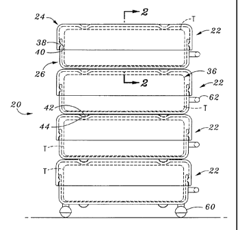
[0040] One embodiment of a tire transport and storage apparatus 20 in
accordance with the
invention is illustrated in Figure 1. In the embodiment illustrated, the
apparatus 20 comprises a
plurality of individual tire transport and storage containers 22.
[0041] In general, each container 22 is configured to house a single tire T.
Referring to Figures
1 and 2, in one embodiment each container 22 comprises a mating first section
or portion 24 and
second section or portion 26. In the position illustrated, the first section
24 may be referred to as
the "top" portion of the container 22, while the second section 26 may be
referred to as the
"bottom" portion of the container 22. It will be appreciated, however, that if
the position of the
container 22 were inverted, the second section 26 would be the "top" of the
container 22 and the
first section 24 the "bottom" of the container 22.
[0042] The first section 24 has a generally circular base portion 28. A wall
30 extends outwardly
from the base portion 26, generally perpendicular thereto. When the base
portion 28 is generally
-6-
CA 02496158 2005-02-18
WO 2004/018328 PCT/US2003/026199
circular, the wall 30 extends in a generally circular periphery. When the
container 22 is in the
position illustrated, the base portion 28 of the first section 24 forms the
"top" of the container 22.
[0043] Likewise, the second or bottom section 26 has a generally circular base
portion 32. A
wall 34 extends outwardly from the base portion 32, generally perpendicular
thereto. When the
container 22 is in the position illustrated, the base portion 32 of the second
section 26 forms the
"bottom" of the container 22.
[0044] The first section 24, including both the base portion 28 and wall 30,
has an inner surface
and an outer surface. Likewise, the second section 26, including both the base
portion 32 and wall
34, has an inner surface and an outer surface.
[0045] Sizes and shapes of the first section 24 and second section 26 may
vary. In the
configuration illustrated and just described, the first and second sections
24,26 are generally
cylindrical in shape, having one closed end. In other embodiments, the first
and second sections
24,26 may have other shapes. For example, the base portion of the first and
second sections 24,26
may be square.
[0046] In the embodiment illustrated where the first and second sections 24,26
are cylinder
shaped, the diameter of the first section 24 preferably slightly exceeds the
diameter of the second
section 26, permitting the wall 30 of the first section 24 to overlap the wall
34 of the second section
26, as best illustrated in Figure 2. In another embodiment, the second section
26 may overlap the
first section 24.
[0047] In one embodiment, the diameter of the first and second sections 24,26
is between about
12 and 48 inches each. The size of the first and second sections 24,26 may
vary, however,
dependent upon the size of the tire to be housed.
[0048] The distance by which the wall 30 of the first section 24 and the wall
34 of the second
section 26 extend outwardly from their respective base 28,32 may also vary.
Preferably, the walls
30,34 extend outwardly a sufficient distance such that the walls 30,34 overlap
when tires of various
_7_
CA 02496158 2005-02-18
WO 2004/018328 PCT/US2003/026199
widths are placed in the container. In one embodiment, the walls 30,34 extend
outwardly about
4 to 24 inches each. Once again, this distance may vary dependent upon the
size of the tire or tires
to be housed. For example, for wider tires, one or both walls 30,34 must
extend outwardly a
greater distance.
[0049] The first and second sections 24,26 may be constructed of a variety of
materials. In one
embodiment, the first and second sections 24,26 are constructed of a durable,
weather resistant
material such as plastic, polyethylene or the like. In one embodiment, the
first and second sections
24,26 are constructed of a material causing them to be generally rigid. In one
embodiment, the first
and second sections 24,26 may be constructed by molding them of a plastic
material.
[0050] Use of the container 22 of the invention will be described in detail
below. In general,
however, the first and second sections 24,26 may be connected to define an
interior space 36 in
which one or more tires may be housed.
[0051 ] In one embodiment, a connecting mechanism or other means is provided
for connecting
the first and second sections 24,26. In one embodiment, this means comprises
one or more
protrusions extending from one of the sections for engagement with one or more
depressions
located on the other section.
[0052] Referring to Figures 1 and 2, in one embodiment the protrusion
comprises a rib 38
extending from the inner surface of the wall 30 of the first section 24. The
depression comprises
a trough 40 located in the outer surface of the second section 26. In other
embodiments, there may
be more than one rib and/or more than one trough. Further, the one or more
ribs may be located
on the second section 26 and the one or more troughs located in the first
section 24. The
protrusions and depressions may comprise other elements, such as dimples for
mating with craters
or protrusions and depressions of other shapes allowing the sections 24,26 to
be securely
connected.
[0053] In one embodiment, the means for connecting permits the first and
second sections 24,26
to be connected in a variety of positions. In one embodiment, a plurality of
troughs may be formed
_g_
CA 02496158 2005-02-18
WO 2004/018328 PCT/US2003/026199
in the second section 26. The troughs are spaced along the wall 34, permitting
the one or more ribs
on the first section 24 to engage the second section 26 in various positions.
[0054] Other means may be provided for connecting the first and second
sections 24,26. In one
embodiment, this means may simply comprise friction between engaging surfaces
of the walls
30,34 of the sections 24,26. Other means such as snaps, clamps, ties, or the
like may be used. For
example, rotating clamps may be connected to one section for engaging a catch
located on the other
section.
[0055] In a preferred embodiment of the invention, the apparatus 20 includes a
plurality of
containers 22. In this manner, the apparatus is configured to house or store a
plurality of tires. In
a preferred embodiment, the containers 22 are configured to be stacked upon
one another in a
vertical relationship. In one embodiment, means are provided for connecting
one or more
containers 22 when in their stacked configuration.
[0056] Figures 1-2 and 4 illustrate one embodiment of a means for connecting
the containers 22.
As illustrated, one or more protrusions extend from one container 22 for
engagement with one or
more depressions location in another container 22. In one embodiment, a
plurality of dimple or
dome-shaped protrusions 42 extend from the base 32 of the bottom section 32 of
the container 22.
A plurality of crater-shaped depressions 44 are located in the base 28 of the
first section 24 of the
container 22. As illustrated, when stacked, the protrusions 42 extending from
one container 22 are
adapted to engage the depressions 44 of a container 22 positioned below it. In
this configuration,
the top and bottom of adjacent containers 22 are connected to one another.
[0057] The one or more protrusions and one or more depressions may have a
variety of shapes
and configurations. Another embodiment of the means for connecting is
illustrated in Figures 3
and 5. As illustrated, a single large protrusion 42a extends upwardly from the
base 28 of the first
section 24 of each container 22. A mating depression 44a is formed in the base
32 of the second
section 26 of the container 22. The protrusion 42a of one container 22 is
configured to mate with
the depression 44a of another container 22 as illustrated.
-9-
CA 02496158 2005-02-18
WO 2004/018328 PCT/US2003/026199
[0058] An additional advantage of this embodiment design is illustrated in
Figure 3. As is
known, tires and most tires mounted upon a wheel include a central generally
circular open section.
In the embodiment illustrated, the base portion 32 of the second section 26
extends upwardly to
define the depression 44a. This portion of the base portion 32 extends into
the central open section
of a tire or tire/wheel combination, centering the tire and maintaining it in
position within the
container 22.
[0059] There may be more than one protrusion and more than one depression, and
their number
and location may vary. The protrusions) may comprise one or more ribs or other
elements, and
the depressions) one or more troughs or other elements. Preferably, the means
for connecting
inhibits the relative movement of stacked containers 22, particularly in the
side-to-side direction.
For example, as illustrated in Figure 11, in one embodiment, an outer or
peripheral ridge 42a
located on one container 22 may be configured to mate with a corresponding
trough 44a on another
container 22.
[0060] Other means may be provided for connecting two or more containers 22.
Figures 6 and
7 illustrate yet another of these means. As illustrated, this means comprises
a post 50 and a locking
member 52. As described above, tires and tires mounted upon wheels generally
have one or more
openings there through. These openings may comprise, for example, a central
bearing or cap
opening, or offset lug bolt openings. In accordance with one embodiment of the
invention, the top
and bottom sections 24,26 of the container 22 have one or more openings there
through. A post
50 is extended through the openings in the containers 22 and the opening or
openings in the
tires/wheels. As illustrated in Figure 6, the post 50 is generally centrally
extending through the
center of the tires T.
[0061] In one embodiment, the post 50 is mounted to a support structure. As
illustrated, the
support structure may comprise a platform 54.
[0062] Containers 22 containing tires T are stacked upon one another on the
platform 54 with
the post 50 passing there through. It will be appreciated that in this
arrangement alone, movement
-10-
CA 02496158 2005-02-18
WO 2004/018328 PCT/US2003/026199
of the containers 22 in the horizontal direction is substantially limited. In
one embodiment,
however, additional means are provided for retaining the containers 22 in
position.
[0063] In one embodiment, at least a portion of the post 50 is threaded. The
locking member
52 engages the post 50. The locking member 52 may be threaded along the post
50 until it engages
the top container 22. The locking member 52 is preferably sized and shaped to
prevent the
containers 22 from being lifted off of the post SO without first removing the
locking member 52.
In addition, if the locking member 52 is threaded downwardly a sufficient
distance, it may engage
the top-most container 22 and transmit a force through the containers 22 which
further prevents
their movement in the horizontal direction.
[0064] Other means may be used to lock or secure the one or more containers 22
to the post 50.
For example, the post SO may have a plurality of openings there through. A
cotter pin, rod or the
like may be passed through the post 50 into engagement with the post 50 in a
desired position along
the post S0.
[0065] The post 50 may comprise a slender rod which is configured to pass
through the tires T
or, when mounted upon wheels, the lug openings in the wheels. In one
embodiment, more than
one rod may be provided, the rods passing through different openings.
[0066] Other means may be provided for securing the containers 22 to one
another. For
example, straps, latches, ties, or the like may be used to connect the
containers 22.
[0067] In one embodiment, means are provided for moving one or more containers
22.
Preferably, the means comprises a means for supporting and moving the
containers 22 by rolling.
Refernng to Figure 1, in one embodiment a plurality of casters 60 are
connected to one of the
containers 22 of the apparatus 20. The casters 60 may have a variety of forms
and may comprise
wheels, bearings or one or more other elements permitting portability of the
one or more containers
22.
-11-
CA 02496158 2005-02-18
WO 2004/018328 PCT/US2003/026199
[0068] Preferably, in one embodiment the apparatus 20 includes a plurality of
containers 22 with
a single container 22 including the casters 60. In this embodiment, the
container 22 including the
casters 60 is located on the bottom when the containers 22 are stacked.
[0069] In one embodiment, as illustrated in Figure 6, the means may include a
support for the
containers, the support being configured in a manner allowing it to be rolled.
In one embodiment,
the support comprises the platform 54 as illustrated. One or more casters 60
are connected to the
platform 54, thus permitting the platform to the rolled. The platform 54 may
be configured to be
rolled in other fashions, including with wheels, rollers or the like. The
platform 54 may be of a
variety of shapes and sizes.
[0070] In one embodiment, the casters 60, rollers or the like may be
removable. For example,
each container 22 may include a plurality of apertures for accepting the stem
of a caster 60. The
user may then attach or detach casters 60 to any of the containers 22. The
platform 54 or other
support may be similarly configured.
[0071 ] In one embodiment, at least one container 22 of the apparatus 20
includes a handle 62.
As illustrated in Figure 1, a handle 62 may extend from each container 22. In
one embodiment,
the handle 62 extends from the second section 26 of the container 22. The
handle 62 may comprise
a member which is connected to the container 22 or be molded in and form a
portion of the
container 22. In one embodiment, the handle 62 defines a gripping portion and
an opening between
the gripping portion and the container 22 through which a portion of a user's
hand may be extended
when grasping the handle 62.
[0072] The handle 62 may have other forms. For example, the handle may
comprise a looped
strap or the like.
[0073] In one preferred embodiment, each container 22 is specifically
configured so that it may
be stored or placed in an upright position. In one embodiment, each container
22 has a generally
flat or planar area, or one or more feet, legs or other support elements
positioned generally opposite
-12-
CA 02496158 2005-02-18
WO 2004/018328 PCT/US2003/026199
the handle 62. In this configuration, a user may set the container 22 in an
upright position on the
planar portion or feet, legs or other support elements.
[0074] The use of the tire transport and storage apparatus 20 in accordance
with the invention
will now be described. In accordance with the invention, a container is
provided for housing one
or more tires T, and an apparatus is provided for transporting and storing one
or more tires.
[0075] In one embodiment, referring to Figure 1, a tire may be stored in a
container 22. The
first and second sections 24,26 of the container 22 are separated. In one
embodiment, the second
section 26 of the container 22 is placed upon a supporting surface, such as
platform 54 or another
container 22. A tire is then located within an area defined by the second
section 26. The first
section 24 is then connected to the second section 26 to enclose the tire T
within an interior space
26 defined by the mating first and second sections 24,26.
[0076] A tire T may be located in the container 22 in other manners. For
example, a tire may
be located in the space defined by the first section 24. The second section 26
may then be
connected to the first section.
[0077] As used herein, the term "tire" may refer to a tire alone or a tire
mounted upon a wheel.
The tire or tire/wheel may include a hub cap, valve stem and other features.
[0078] As indicated, in order to enclose the tire T in the container 22, the
first and second
sections 24,26 are connected to one another. In one embodiment, this step
comprises lowering the
first section 24 over the second section 26. As described above, this
preferably results in the wall
30 of the first section 24 overlapping the wall 34 of the second section 26.
[0079] Preferably, this step includes the step of connecting the first and
second sections 24,26
with the means for connecting. In one embodiment, this step comprises engaging
the one or more
ribs 28 on the first section 24 with the one or more troughs 40 on the second
section. In a preferred
embodiment, the first section 24 is lowered until at least a portion of the
base 38 thereof engages
the tire or wheel.
-13-
CA 02496158 2005-02-18
WO 2004/018328 PCT/US2003/026199 .-
[0080] In accordance with the invention, one or more tires T may be stored
using one or more
containers 22. The one or more tires T are located in the one or more
containers 22 in the manner
just described.
[0081 ] In one embodiment of the invention, the apparatus 20 comprises a
plurality of containers
and the method of use of the apparatus 20 includes connecting or linking the
containers 22. As
illustrated in Figures 1 and 2, in one embodiment the containers 22 are
vertically stacked. Thus,
in accordance with the method of use, the user stacks containers 22 containing
tires T. For
example, as illustrated, a user may store four tires T by locating each of the
tires T in a single
container 22 and stacking the containers. Of course, the containers 22 need
not be loaded and then
stacked, but may be loaded as they are stacked.
[0082] As illustrated, in one embodiment, the containers 22 are stacked in a
manner utilizing the
means for connecting the containers 22. In the embodiment illustrated in
Figures 1-2 and 4, this
comprises aligning the protrusions 42 extending from the base 32 of the second
section 26 of one
container 22 with the depressions 44 formed in the base 28 of the first
section 24 of a mating
container 22. In the embodiment illustrated in Figures 3 and 5, this comprises
aligning the single
protrusion extending from the second section 26 of one container 22 with the
depression formed
in the first section 24 of a mating container 22.
[0083 ] Once a tire or tires are housed, they may be easily transported in the
container 22. In one
embodiment, the tire or tires may be transported by carrying them in the
container 22 in a suitcase
-like manner. In this arrangement, a user grasps the handle 62 and picks up
the container 22 to
transport it.
[0084] As illustrated, the containers 22 may be stacked in succession. In the
embodiment
illustrated, four tires T are stored by locating them in four stacked
containers 22.
[0085] The containers 22 may be stacked in a variety of fashions. In a
preferred embodiment,
when one of the containers 22 is provided with casters 60, that container 22
is located on the
-14-
CA 02496158 2005-02-18
WO 2004/018328 PCT/US2003/026199
bottom of the stack. Once that container 22 is filled, the second section 26
of the next container
22 may be located on the first container. A tire T may be located in that
portion of the container
22, and then the first section 24 connected to the second section 26, and so
on until all the tires T
have been housed and stacked.
[0086] In accordance with the invention, the method of use includes moving the
tires T. In a
preferred embodiment, the tires may be transported by locating them in the
containers 22. In the
embodiment illustrated in Figure 1, the stacked containers 22 may be rolled
upon the casters 60
about a surface.
[0087] A user may grasp one of the handles 62 in order to move a container 22
or to move the
entire stack of containers 22. The user may engage other surfaces, such as the
top container 22,
in order to move the stack of containers.
[0088] The method of using the apparatus illustrated in Figures 6 and 7 is
similar to that
described above. In this embodiment, however, the containers 22 are located on
the pole 50. In
particular, the user passes the pole SO through each section of each container
22, as well as the tire
which is housed by each container. The user then secures the containers 22 to
one another using
the locking member 52. As described above, the locking member 52 may be
threaded upon the
post 50 until it engages the top-most container 22.
[0089] In this embodiment, transport or movement of the containers 22 is
generally the same.
In this embodiment, the containers 22 are moved by rolling the apparatus 20,
including the
platform 54, about a surface using the casters 60.
[0090] The apparatus of the invention has numerous advantages which will now
be appreciated.
In accordance with the invention, an apparatus is provided for transporting
and storing or housing
one or more tires. In accordance with the invention, one or more tires are
located within one or
more generally enclosed containers or housings. The one or more containers
prevent the one or
more tires from contacting people and other items, and thus prevents the one
or more tires from
transferring dirt or the like. In the event the one or more tires are studded
snow tires, the container
-15-
CA 02496158 2005-02-18
WO 2004/018328 PCT/US2003/026199
prevents the studs from snagging items such as a person's clothing. Because
the one or more tires
are enclosed, the container enclosing the one or more tires may be located in
a garage where it may
otherwise be undesirable to store the tire(s).
[0091 ] Most importantly, the one or more tires are safely stored. In
particular, the tire or tires
are stacked in a secure fashion, preventing them from rolling or tipping over,
thus preventing
damage or injury. As may be appreciated, tires may form the basis of liability
for a homeowner.
As indicated above, the tires may roll out of control from a garage and hit a
person or property
causing damage or injury. Alternatively, stacked tires may tip over. Tires may
also soil another
person's clothes or the like. In accordance with the invention, one or more
tires may be securely
and safely stored in a manner reducing the likelihood of these accidents.
[0092] 1n accordance with the invention, the container houses the one or more
tires in an
aesthetically pleasing fashion. When assembled and stacked, the containers
present an organized
and pleasing storage apparatus.
[0093] Once stored in their containers, tires are protected from the elements.
For example, the
tires are protected from sunlight, rain, chemicals and other elements which
may damage the tires
if they were exposed to such during storage.
[0094] A particular advantage of the invention is that a plurality of
individually housed or stored
tires may be stacked. The stacked arrangement of the stored tires minimizes
occupied space. As
is known, in garages and similar locations, vertical space is often available,
while horizontal space
is at a premium. In accordance with the invention, the horizontal space
occupied by the apparatus
is minimized by storing the tires in a stacked or vertical arrangement.
[0095] In accordance with the invention, one or more tires may be easily
transported. First, a
container may be transported using the handle of that container, in a suitcase-
like fashion. As one
example, a party may need to transport a flat tire to a tire service center.
The party may carry the
tire housed in a container to their car using the handle. The tire is not only
easily transported, but
the user is protected from the tire soiling their car, body or clothes. In
addition, the party may
-16-
CA 02496158 2005-02-18
WO 2004/018328 PCT/US2003/026199
easily load the tire into their car for transport. The tire is prevented from
rolling about inside their
car while traveling, and their car is also protected from damage, such as from
soiling or the like.
[0096] The one or more tires may also be transported using the rollers or the
other means for
moving. In a preferred embodiment, one or more tires may be moved by locating
them in one or
more containers including the casters or wheels, or by locating the one or
more containers upon the
platform having casters or wheels. In one embodiment, a plurality of tires are
placed in containers
which are stacked. The 'entire stack is then moved using the casters or
wheels. In this manner, one
or more tires are conveniently moved.
[0097] A variety of other embodiments of apparatus are contemplated. In one
embodiment, the
container of the invention may be configured to house more than one tire. For
example, the
container may comprise a tall cylinder in which two or more tires may be
stacked. The container
may again include a first section and second section. In this embodiment, the
first or top section
may comprise a lid.
[0098] In one embodiment, the containers are substantially rigid. In another
embodiment, the
container may be made of a pliable material. For example, in one embodiment,
the apparatus may
comprise a platform 54 upon which the one or more tires may be stacked. As
illustrated in Figures
8A and 8B, the apparatus may include a generally cylindrical fabric curtain 64
which may be
lowered to expose the one or more tires or raised about the one or more tires
to obscure or enclose
the one or more tires T. The fabric curtain may be, for example, made of a
durable woven nylon,
canvas or a wide variety of other materials.
[0099] In one embodiment, the container or containers need not include wheels.
As described
above, the container or containers may be transported using a handle or other
means.
[0100] In one embodiment, each container may be configured so it may be stored
in an upright
or vertical position. By a generally upright or vertical position it is meant
that the container is
positioned so that an axis extending through the center of the tire or tires
therein is generally
-17-
CA 02496158 2005-02-18
WO 2004/018328 PCT/US2003/026199
parallel to the ground or other support surface, or in other words in
generally the same position as
a tire when placed on a vehicle.
[0101 ] In this embodiment, multiple containers may be stored by placing
generally vertically
oriented containers adjacent to one another in a horizontal row. As described
above, and as
illustrated in Figure 9, the container 22 may include a planar area 70 or
alternatively, feet, legs or
other support elements which allow the container to be placed on a support
surface in an upright
position. In such a configuration, the container may be stored in an upright
or vertical position by
placing it on a support surface, such as a garage floor, shelf or the like.
[0102] In accordance with this embodiment of the invention, means may be
provided for
transporting the container in its upright/vertical or substantially
upright/vertical position. As
indicated above and as illustrated in Figure 10, such a means may comprise or
include a handle 68.
As described, the handle 68 may be used to transport the container in
"suitcase"-like fashion. In
one embodiment, the handle 68 may be retracted when not in use. When in use,
the handle 68 may
be extended so that the user may pull the container 22 behind them.
[0103] In addition, or alternatively, as also illustrated in Figure 10, the
container 22 may include
one or more wheels 66, casters or the like. In this embodiment, the wheels 66
may be located on
the side of the container 22, such as at the planar portion or the feet, legs
or other support elements,
instead of the bottom. In one embodiment, wheels 66 may be provided which
permit the container
to be rolled about in its vertical position. In another embodiment, wheels 66
may be provided
which permit the user to tip the container onto the wheels 66 and then roll
the container 22. In one
or more embodiments, the container may include multiple sets of wheels or
casters for moving the
container in either its horizontal or vertical position.
[0104] It will be appreciated that elements other than wheels may be used. For
example,
cylindrical or ball rollers may be utilized to permit the container to be
transported.
[0105] In one embodiment, the container may include means for hanging or
mounting the
container to another element, such as a wall. In one embodiment, as
illustrated in Figure 13B, the
-18-
CA 02496158 2005-02-18
WO 2004/018328 PCT/US2003/026199
handle may comprise a strap 78 which may be connected to a hook 80 or other
element, permitting
the container 22 to be hung.
[0106] In another embodiment, as illustrated in Figure 13A, the container may
include a slot 74
for accepting a hooking mechanism 76 such as an outwardly extending bolt or
other element. The
container 22 may be connected to the hooking mechanism 76 or other element,
allowing the
container to be hung.
[0107] In another embodiment, the container may include a mounting element,
such as a hanger
or hanging element which may be formed in or connected to the container. The
hanger may be
used to connect the container to another element, such as a hook or the like,
again permitting the
container to be hung.
[0108] In one or more embodiments, the containers may be specifically
configured to aid in their
transport and storage, such as from a point of manufacture to a point of sale,
and from a point of
sale to a user's home. In one embodiment, as described above, the first and
second sections 24,26
may have different diameters. In this embodiment, the section having the
smaller diameter may
be inverted and stored within the other section. In this manner the sections
may be stacked and
occupy less space, such as for transport and display.
[0109] In another embodiment, the containers may be of different sizes. For
example, the
bottom container may be the largest, with each successive container being
smaller. In this
configuration, the smallest container may be located within the next largest,
and so on. The
containers thus nest within one another and may all be stored within the
largest container (such as
the bottom container including wheels or casters). In this embodiment, all of
the containers may
thus be transported and stored in their empty state while occupying the least
amount of space.
[0110] In one embodiment, the containers need not completely enclose the
tires. For example,
as illustrated in Figure 12, the first and/or second sections of a container
22 may include one or
more holes 72 or openings. The holes 72 or openings may be used to permit
liquid to drain from
the container 22 or to permit the exchange of air.
-19-
CA 02496158 2005-02-18
WO 2004/018328 PCT/US2003/026199
[0111 ] In one embodiment, the containers may be of a variety of colors,
including color coded
for use. In the case where the containers are molded of a plastic material,
the plastic may be red,
black, yellow or a variety of other colors. In the case where the containers
are made of other
materials, such as fabric, the fabric may be colored. The coloring may be used
to designate a size
of the container. For example, a container having a first size (such as large
for truck wheels) may
be black. A container of another size (such as for the tires of a small import
car) may be yellow.
In this manner, the color coding aids in defining the size of the container
and thus the size of tire
the container will hold. The color coding may also be used to designate front
or rear tire storage.
For example, a consumer may utilize a pair of red containers to store their
front tires and green
containers to store their rear tires. In this manner, the consumer can ensure
that the tires are
properly placed onto their vehicle at a later time.
[0112] As described above, the containers may be constructed of a pliable
material such as a
fabric. One embodiment of such a container is illustrated in Figures 8A and
8B, the container
comprising a fabric curtain. This curtain is preferably configured to house or
contain multiple tires.
[0113] As illustrated in Figure 14, in one embodiment such a container 122
constructed entirely
or partially of a pliable material may be configured to contain as few as one
tire. In the
embodiment illustrated in Figure 14, the container 122 has a first section 124
and a second section
126. Means are provided for selectively coupling the first and second sections
124,126 to define
a closed or generally closed interior space for housing a tire.
[0114] As illustrated, the container 122 is constructed of a durable fabric
material and is shaped
to fit around or enclose a tire. In one embodiment, the means for coupling
comprises a zipper 138.
A first half of the zipper is associated with the first section 124 and a
second, mating portion of the
zipper is associated with the second section 126. In one embodiment, the
portions of the zipper
138 are located at or near an edge of the section and designed to meet at a
peripheral portion of the
container.122.
-20-
CA 02496158 2005-02-18
WO 2004/018328 PCT/US2003/026199
[0115] The zipper may be opened or closed. When opened, the first and second
sections
124,126 may be moved away from one another to permit placement of tire
therein. When closed,
the container 122 surrounds or encloses the tire therein.
[0116] In one embodiment, at least a portion of the first and second sections
124,126 are
permanently connected to prevent their separation. For example, the zipper 138
need not extend
entirely around the edge of the sections 124,126.
[0117] Other means may provided for coupling the first and second sections
124,126. For
example, hook and loop fastening material may be utilized. For example, hook
material may be
located about the edge of the first section 124 and mating loop material
located about the edge of
the second section 126. The material may be in a continuous strip or in spaced
segments. Other
means for coupling may include buttons, clips, clasps and straps.
[0118] In one embodiment, the container 122 may generally have the form of a
bag. For
example, the container 122 may be closed except at one location. At that
location, the first and
second sections 124,126 may be opened, such as in the form of a top of a bag,
to fit a tire or tires
into the container 122. Of course, the size of the opening is selected so that
the tire may be placed
there through. The bag opening may then be closed, such as with a draw string,
zipper or other
means for selectively closing. In this configuration, the body forming the
container 122 may be
constructed as a single element, or of a plurality of individual elements,
such as fabric panels which
are connected to one another.
[0119] As also indicated above, a variety of means may be utilized to connect
containers to one
another. Figure 14 illustrates another such means. As illustrated, this means
comprises mating
hook and loop fastening material. As illustrated, in one embodiment hook or
loop material 127 is
located on a top portion 128 of the container 122 and hook or loop material
127 is located on a
bottom portion 132 of the container. In one embodiment, as illustrated,
material 127 is in the form
of a generally circular strip of material.
-21-
CA 02496158 2005-02-18
WO 2004/018328 PCT/US2003/026199
[0120] The hook or loop material 127 is configured to mate with corresponding
material located
on another container 122. In a preferred embodiment, hook material is located
on a top portion of
each container and loop material on a bottom portion of each container to
permit a sequence of
containers to connect in a stacked vertical relationship, as illustrated. In
another preferred
embodiment, loop material is located on a top portion of each container and
hook material on a
bottom portion of each container to permit a sequence of containers to
connect.
[0121 ] Another means for connecting the containers is illustrated in Figure
14. This means may
be used in addition to or separate from the means just described. As
illustrated, one or more or
each container 122 includes a handle 162. The handle 162 may be a rigid, or
may simply comprise
a loop of flexible material connected to the container 122. One or more or
each container 122 also
includes a strap 163. The strap 163 has a first end connected to the container
122 and a second free
end. The strap 163 is of sufficient length to permit it to extend and connect
to the handle 162 of
another container. In one embodiment, the strap 163 includes hook and loop
material or other
means for connecting which permit the strap 163 to close upon itself to form a
closed loop about
the handle 162. Other means such as snaps or buckles may be used to close the
strap 163 upon
itself into a closed loop about the handle 162.
[0122] In another embodiment, the strap 163 may be configured to attach to the
handle 162
directly, such as with a snap. In another embodiment, each container 122 may
include a strap, the
straps of mating containers including means for connecting them, such as hook
and loop material.
[0123] Another embodiment container 222 is illustrated in Figures 15A and B.
This
embodiment container 222 includes a generally rigid and flat top or first
member 228 and bottom
or second member 230. The top and bottom members 228, 230 may be constructed,
for example,
of molded plastic. In the embodiment illustrated, the top and bottom members
228,230 are
generally rigid, planar plastic discs.
[0124] A first section 224 of the container 222 includes the top member 228
and a fabric or other
flexible, preferably lightweight material extending therefrom to form a wall
232. Likewise, a
second section 226 of the container 222 includes the bottom member 230 and
fabric or other
-22-
CA 02496158 2005-02-18
WO 2004/018328 PCT/US2003/026199
flexible, preferably lightweight material extending therefrom to form a wall
232. The first and
second sections 224,226 may be configured to couple to one another in the
manner described
above, such as by a zipper or mating hook and loop material. The material
forming the wall 232
may comprise canvas, nylon or a variety of other materials. Preferably, the
material is durable and
may be expanded and compressed as detailed below.
[0125] As illustrated in Figure 15A, the fabric or other material forming the
wall 230 may be
extended away from the top and bottom members 228,230 to expand the container
222 to
accommodate a tire therein. As illustrated in Figure 15B, the fabric or other
material forming the
wall 232 may also be compressed. In that state, the container 222 is generally
flat and
accommodates storage and transport.
[0126] This embodiment container 222 has the advantage that the generally
rigid top and bottom
portions 228,230 provide structural rigidity to the container 222. The top and
bottom portions
228,230 thus provide support, such as when placing the container 222 housing
tire on another
surface.
[0127] At the same time, the fabric or other material forming the walls 232
permits the container
to 222 be compressed to a generally flat position, such as when the container
222 is being
transported or stored. Also, the fabric material may be expanded so that the
container 222 is large
enough to house a tire.
[0128] Yet another embodiment container 322 is illustrated in Figure 16. In
this embodiment,
the container 322 includes a generally planar, rigid base 328. Flexible
material, such as fabric,
preferably comprises the remainder of the container 322.
[0129] In one embodiment, the fabric or other material forms first and second
sections 324,326.
Means, such as a zipper, hook and loop material or the like preferably permits
the first and second
sections 324,326 to be connected or disconnected in the manner described
above.
-23-
CA 02496158 2005-02-18
WO 2004/018328 PCT/US2003/026199
[0130] The size and shape of the base 328 may vary. The base 328 is preferably
configured to
provide a stable, flat support for the container 322. In this configuration,
the base 328 is actually
located at the tread-side of a tire located therein (i.e. the "periphery" of
the container), so that the
container 322 stores the tire in an upright position.
[0131] Like the container 222 illustrated in Figures 15A and 15B, the
container 322 illustrated
in Figure 16 has the benefit that it may be stored and transported in a
collapsed, generally flat state.
On the other hand, the fabric material forming the first and second sections
324,326 may be
expanded to house a tire, as in the position illustrated in Figure 16.
[0132] It will be appreciated that the device of the invention may include one
or more of the
above-described features in various combinations other than that specifically
described. For
example, the container 20 illustrated in Figure 1 may include a hanger and may
be configured to
be positioned vertically. Likewise, the containers 122,222,322 may be stored
and transported on
platform or similar member as illustrated in Figure 6, and may be stored by
hanging as illustrated
in Figures 13A and 13B. The containers 122,222,322 may also include means for
transporting
them in a generally upright position, such as a handle as illustrated in
Figure 10.
[0133] It will be understood that the above described arrangements of
apparatus and the method
therefrom are merely illustrative of applications of the principles of this
invention and that many
other embodiments and modifications may be made without departing from the
spirit and scope
of the invention as defined in the claims.
-24-