Language selection

Search

Patent 2496522 Summary

Third-party information liability

Some of the information on this Web page has been provided by external sources. The Government of Canada is not responsible for the accuracy, reliability or currency of the information supplied by external sources. Users wishing to rely upon this information should consult directly with the source of the information. Content provided by external sources is not subject to official languages, privacy and accessibility requirements.

Claims and Abstract availability

Any discrepancies in the text and image of the Claims and Abstract are due to differing posting times. Text of the Claims and Abstract are posted:

  • At the time the application is open to public inspection;
  • At the time of issue of the patent (grant).
(12) Patent: (11) CA 2496522
(54) English Title: RUN IN COVER FOR DOWNHOLE EXPANDABLE SCREEN
(54) French Title: COUVERCLE D'ENTREE POUR CREPINE EXPANSIBLE DE FOND
Status: Deemed expired
Bibliographic Data
(51) International Patent Classification (IPC):
  • E21B 43/10 (2006.01)
  • E21B 43/08 (2006.01)
(72) Inventors :
  • HOVEM, KNUT A. (United States of America)
(73) Owners :
  • BAKER HUGHES INCORPORATED (United States of America)
(71) Applicants :
  • BAKER HUGHES INCORPORATED (United States of America)
(74) Agent: MARKS & CLERK
(74) Associate agent:
(45) Issued: 2008-10-14
(86) PCT Filing Date: 2003-07-31
(87) Open to Public Inspection: 2004-03-11
Examination requested: 2005-07-11
Availability of licence: N/A
(25) Language of filing: English

Patent Cooperation Treaty (PCT): Yes
(86) PCT Filing Number: PCT/US2003/023911
(87) International Publication Number: WO2004/020787
(85) National Entry: 2005-02-22

(30) Application Priority Data:
Application No. Country/Territory Date
10/231,821 United States of America 2002-08-28

Abstracts

English Abstract


A screen to be expanded when placed downhole is disclosed. The screen is
delivered to the location with a cover that blocks access to the screen from
well fluids. Circulation or reverse circulation can be undertaken with no
appreciable flow through the screen due to placement of the cover. In one
embodiment the cover has slits (16) that open to be diamond shapes (18) upon
expansion of the underlying screen. In another embodiment, the openings are
created by shapesthat have a weakened edge that, as a result of expansion
break off to create available openings for flow.


French Abstract

La présente invention a trait à une crépine destinée à se dilater lors de sa mise en place en fond de puits. La crépine est délivrée à l'emplacement avec un couvercle qui interdit la pénétration de la crépine par des fluides de puits. La circulation ou la circulation inverse peut s'effectuer sans écoulement perceptible à travers la crépine grâce au placement du couvercle. Dans un mode de réalisation, le couvercle présente des fentes (16) qui s'ouvrent de manière biconique (18) lors de la dilatation de la crépine sous-jacente. Dans un autre mode de réalisation, les ouvertures sont crées par des formes présentant des bords fragilisés qui, grâce à l'expansion se rompent pour créer des ouvertures aptes à un écoulement.

Claims

Note: Claims are shown in the official language in which they were submitted.


What is claimed is:


1. A method of well completion, comprising:

covering an exterior surface of a screen with a substantially extensible
sleeve;
running the screen and sleeve downhole;

configuring said sleeve to allow some flow, during a circulation or reverse
circulation or
run in, through radial flow paths through said screen;

expanding said screen and said sleeve without severing said sleeve from a top
to a bottom
end; and

enlarging said flow paths in said screen by said expanding.
2. The method of claim 1, comprising:

providing a plurality of lines on said sleeve;

increasing stress along said lines due to said expanding; and
separating said sleeve along said lines.

3. The method of claim 2, comprising:
making said plurality of lines straight.
4. The method of claim 3, comprising:

making said plurality of lines parallel.
5. The method of claim 4, comprising:


aligning said parallel lines with the longitudinal axis of said screen.
6. The method of claim 3, comprising:

creating diamond shaped openings in said sleeve by said separation along said
lines.
7. The method of claim 2, comprising:

configuring said lines in a closed geometric shape.
8. The method of claim 7, comprising:

defining covers for potential openings in said sleeve with said geometric
shapes.
9. The method of claim 2, comprising:

forming said lines by scoring said sleeve.
10. The method of claim 2, comprising:

forming said lines by a plurality of adjacent perforations.
11. The method of claim 1, comprising:

releasing said sleeve from said screen by said expanding.
12. The method of claim 11, comprising:

allowing the sleeve to move away from said screen; and


6


engaging the wellbore with the screen.
13. The method of claim 1, comprising:
providing a plurality of lines on said sleeve;

increasing stress along said lines due to said expanding;
separating said sleeve along said lines;

configuring said lines in a closed geometric shape;

defining covers for potential openings in said sleeve with said geometric
shapes; and
separating said covers from said sleeve by said expanding.

14. The method of claim 13, comprising:

changing said closed geometric shape due to said expanding.
15. The method of claim 14, comprising:

changing a circular initial geometric shape to an oval shape due to said
expanding.
16. The method of claim 13, comprising:

blocking all flow through said screen with said sleeve prior to said
expanding.
17. The method of claim 16, comprising:

circulating or reverse circulating longitudinally through the body of said
screen prior to
said expanding.


7


18. The method of claim 1, comprising:
providing a seam on said sleeve; and

breaking said seam at least in part from said expanding.
19. The method of claim 1, comprising:

providing said sleeve in the form of a scroll;
securing said scroll to said screen; and

releasing said scroll at least in part by said expanding.


8

Description

Note: Descriptions are shown in the official language in which they were submitted.


CA 02496522 2007-09-04

RUN IN COVER DOWNHOLE EXPANDABLE SCREEN
FIELD OF THE INVENTION

[ 0001] The field of this invention is expandable downhole screens and more
particularly, a cover
for the screen for run in that blocks flow through the screen and upon
expansion permits flow
through the screen.

BACKGROUND OF THE INVENTION

[ 0002] Screens are now being expanded downhole to take the place of a gravel
packing operation.
Several U.S. Patents reveal the technology used to expand screens downhole. A
few examples are
U.S. Patents 5,901,789; 6,315,040 and 5,366,012. In running screens to the
desired position in the
wellbore, there was a problem of screen plugging before expansion could take
place. The fact that
the screen openings were exposed also precluded forced circulation to remove
welibore debris before
expanding the screen.

[ 0003] In the past, screens that were not expanded were covered with a
movable sleeve. In U.S.
Patents 5,443,121 and 5,617,919, a movable sleeve was used to facilitate
distribution of gravel
outside the screen. U.S. Patent 5,355,956 shows a cover sleeve over a screen
with sacrifieial plugs
in holes that are eventually removed after the screen is positioned by
introducing a chemical to
dissolve the plugs. Finally, U.S. Patent 3,099,318 shows a sheath or belts
around a multi-layered
filter material to compress it for run in. When the assembly is in place a
chemical is introduced to
remove the sheath or bands and allow the filter layers to expand to their
natural thickness. The sheath
or rings for compression can also be released by defeating a lock when the
screen is in the desired


CA 02496522 2007-09-04

position downhole. Compression of the screen is required so that it can run
downhole where it can
later expand and work more efficiently, according to this reference.

[0004] The present invention allows the openings in the screen to be closed
during run in and
downhole fluid circulation or reverse circulation. When the screen is
expanded, the covering on the
screen allows flow by a variety of techniques. The covering can be ripped off
due to expansion or
openings in the covering can develop due to the screen expansion, to name a
few techniques. These
and other aspects of the present invention will be more readily appreciated by
on skilled in the art
from a review of the description of the preferred embodiment and the claims,
which appear below.
SUMMARY OF THE INVENTION

[0005] A screen to be expanded when placed downhole is disclosed. The screen
is delivered to the
location with a cover that blocks access to the screen from well fluids.
Circulation or reverse
circulation can be undertaken with no appreciable flow through the screen due
to placement of the
cover. In one embodiment the cover has slits that open to be diamond shapes
upon expansion of the
underlying screen. In another embodiment, the openings are created by shapes
that have a weakened
edge that, as a result of expansion break off to create available openings for
flow.

2


CA 02496522 2007-09-04

[0005a] Accordingly, in one aspect of the present invention there is provided
a method of well
completion, comprising:

covering an exterior surface of a screen with a substantially extensible
sleeve;
running the screen and sleeve downhole;

configuring said sleeve to allow some flow, during a circulation or reverse
circulation or run
in, through radial flow paths through said screen;

expanding said screen and said sleeve without severing said sleeve from a top
to a bottom end;
and

enlarging said flow paths in said screen by said expanding.
DETAILED DESCRIPTION OF THE DRAWINGS

Embodiment of the present invention will now be described more fully with
reference to the
accompanying drawings in which:

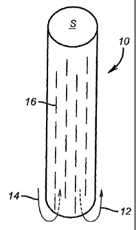
[0006] Figure 1 is an elevation view of one embodiment of a cover for a screen
prior to expansion;
[0007] Figure 2 is the view of Figure 1 after the screen is expanded;

100081 Figure 3 is an alternative embodiment of the cover for the screen prior
to screen expansion;
[0009] Figure 4 is the view of Figure 3 after screen expansion.

2a


CA 02496522 2005-02-22
WO 2004/020787 PCT/US2003/023911
DETAILED DESCRIPTION OF THE PREFERRED EMBODIMENT

[ 0010] Figure 1 shows one embodiment of the sleeve 10. It has a cylindrical
shape to fit over a
screen S so as to effectively close off its openings (not shown) in the event
there is circulation,
represented by arrow 12 or reverse circulation, represented by arrow 14 when
the screen S is being
run into position covered by sleeve 10. Sleeve 10 has a plurality of slits 16
that are shown arranged
in longitudinal rows, although other arrangements or a random pattern is
within the scope of the
invention. The slits 16 are preferably straight but they don't have to be. The
slits 16 can be right
through the sleeve 10 during run in over their entire length. Alternatively,
they may just be surface
depressions to concentrate stress during expansion of sleeve 10 such that the
depressed areas rip and
create the generally diamond shaped openings 1S shown in Figure 2. In these
configurations the
sleeve 10 can be seamless or have a welded or fused seam 20. In another
variation, the seam 20 can
be designed to break on expansion of the screen S so that either the entire
sleeve 10 drops away from
the screen S during expansion or it stays in the vicinity of screen S with a
partially or totally failed
seam 20 and some or all of the slits or depressions 16 having opened as
openings 18. The slits or
depressions 16 can be made from a succession of very small openings that are
large enough to
concentrate stress on expansion to create openings 18, yet small enough on run
in to block any
significant flow through screen S.

[ 0011] Figures 3 and 4 show oval, elliptical or circular or schematically
other shapes 22 that define
a depression, a series of small perforations, or partial cut-through
locations. Upon expansion of the
screen S, the shapes 22 formed as previously described part away fully or
partially from the balance
of the sleeve 10 to create a plurality of openings 24. Openings 24 may be
fully open or may have
partial cover depending on whether the shape 22 has fully separated or
partially separated from
3


CA 02496522 2005-02-22
WO 2004/020787 PCT/US2003/023911
sleeve 10 due to the expansion of screen S. Comparing Figure 4 to Figure 3, it
can be seen that the
expansion has changed the shape of the openings 24 from the point of the shape
they had when
covered by shapes 22. Figure 4 schematically shows that the shapes 22 may fall
away as a result of
expansion of screen S. As before, the embodiment of Figures 3 and 4 can have a
seam that partially
or totally fails on expansion of screen S. The results can vary from having
the entire sleeve 10 fall
away due to expansion or it can slide down with some or all of the shapes that
initially act as covers
22 falling away or being otherwise displaced to open fully or in part one or
more openings 24.

f 0012] The sleeve 10 can be used with a variety of known screens. It can
protect the screen from
damage during run in from physical impacts. It can also close off the openings
in the screen to
moving well fluids in either direction. The screen S is less likely to be
obstructed when it is
expanded into contact with the wellbore. The sleeve 10 can have openings
develop due to expansion
in a variety of ways. Covers 22 can move or fall away leaving openings 24 for
screen access. The
sleeve can also have a seam that comes apart totally or partially. It can be a
scroll retained by bands
that yield or fail allowing the scroll to partially or totally unravel and/or
slits 16 or covers 22 to create
access paths such as 18 or 24.

[ 0013] The above description is illustrative of the preferred embodiment and
many modifications
may be made by those skilled in the art without departing from the invention
whose scope is to be
determined from the literal and equivalent scope of the claims below:

4

Representative Drawing
A single figure which represents the drawing illustrating the invention.
Administrative Status

For a clearer understanding of the status of the application/patent presented on this page, the site Disclaimer , as well as the definitions for Patent , Administrative Status , Maintenance Fee  and Payment History  should be consulted.

Administrative Status

Title Date
Forecasted Issue Date 2008-10-14
(86) PCT Filing Date 2003-07-31
(87) PCT Publication Date 2004-03-11
(85) National Entry 2005-02-22
Examination Requested 2005-07-11
(45) Issued 2008-10-14
Deemed Expired 2021-08-03

Abandonment History

There is no abandonment history.

Payment History

Fee Type Anniversary Year Due Date Amount Paid Paid Date
Registration of a document - section 124 $100.00 2005-02-22
Application Fee $400.00 2005-02-22
Maintenance Fee - Application - New Act 2 2005-08-01 $100.00 2005-02-22
Request for Examination $800.00 2005-07-11
Maintenance Fee - Application - New Act 3 2006-07-31 $100.00 2006-07-10
Maintenance Fee - Application - New Act 4 2007-07-31 $100.00 2007-07-18
Final Fee $300.00 2008-06-23
Maintenance Fee - Application - New Act 5 2008-07-31 $200.00 2008-07-15
Maintenance Fee - Patent - New Act 6 2009-07-31 $200.00 2009-06-30
Maintenance Fee - Patent - New Act 7 2010-08-02 $200.00 2010-06-30
Maintenance Fee - Patent - New Act 8 2011-08-01 $200.00 2011-06-30
Maintenance Fee - Patent - New Act 9 2012-07-31 $200.00 2012-07-16
Maintenance Fee - Patent - New Act 10 2013-07-31 $250.00 2013-06-12
Maintenance Fee - Patent - New Act 11 2014-07-31 $250.00 2014-07-08
Maintenance Fee - Patent - New Act 12 2015-07-31 $250.00 2015-07-08
Maintenance Fee - Patent - New Act 13 2016-08-01 $250.00 2016-07-06
Maintenance Fee - Patent - New Act 14 2017-07-31 $250.00 2017-07-05
Maintenance Fee - Patent - New Act 15 2018-07-31 $450.00 2018-07-11
Maintenance Fee - Patent - New Act 16 2019-07-31 $450.00 2019-06-21
Maintenance Fee - Patent - New Act 17 2020-07-31 $450.00 2020-06-23
Owners on Record

Note: Records showing the ownership history in alphabetical order.

Current Owners on Record
BAKER HUGHES INCORPORATED
Past Owners on Record
HOVEM, KNUT A.
Past Owners that do not appear in the "Owners on Record" listing will appear in other documentation within the application.
Documents

To view selected files, please enter reCAPTCHA code :


To view images, click a link in the Document Description column. To download the documents, select one or more checkboxes in the first column and then click the "Download Selected in PDF format (Zip Archive)" or the "Download Selected as Single PDF" button.

List of published and non-published patent-specific documents on the CPD .

If you have any difficulty accessing content, you can call the Client Service Centre at 1-866-997-1936 or send them an e-mail at CIPO Client Service Centre.


Document
Description 
Date
(yyyy-mm-dd) 
Number of pages   Size of Image (KB) 
Representative Drawing 2008-09-30 1 4
Cover Page 2008-09-30 2 37
Abstract 2005-02-22 1 53
Claims 2005-02-22 4 82
Drawings 2005-02-22 1 17
Description 2005-02-22 4 177
Representative Drawing 2005-02-22 1 3
Cover Page 2005-04-29 1 33
Claims 2005-02-23 3 66
Claims 2007-09-04 4 67
Description 2007-09-04 5 185
PCT 2005-02-22 13 408
Assignment 2005-02-22 7 270
Prosecution-Amendment 2005-07-11 1 48
Prosecution-Amendment 2007-03-02 3 111
Prosecution-Amendment 2007-09-04 11 332
Correspondence 2008-06-23 1 57