Language selection

Search

Patent 2497016 Summary

Third-party information liability

Some of the information on this Web page has been provided by external sources. The Government of Canada is not responsible for the accuracy, reliability or currency of the information supplied by external sources. Users wishing to rely upon this information should consult directly with the source of the information. Content provided by external sources is not subject to official languages, privacy and accessibility requirements.

Claims and Abstract availability

Any discrepancies in the text and image of the Claims and Abstract are due to differing posting times. Text of the Claims and Abstract are posted:

  • At the time the application is open to public inspection;
  • At the time of issue of the patent (grant).
(12) Patent Application: (11) CA 2497016
(54) English Title: A DEVICE FOR MEASURING A MAXIMUM LOAD ALLOWED FOR LIFT PLATFORMS
(54) French Title: DISPOSITIF POUR MESURER LA CHARGE MAXIMALE PERMISE SUR LES PLATES-FORMES ELEVATRICES
Status: Deemed Abandoned and Beyond the Period of Reinstatement - Pending Response to Notice of Disregarded Communication
Bibliographic Data
(51) International Patent Classification (IPC):
  • B66F 17/00 (2006.01)
  • G01G 03/00 (2006.01)
  • G01G 19/14 (2006.01)
(72) Inventors :
  • MAGNI, RICCARDO (Italy)
(73) Owners :
  • MANITOU COSTRUZIONI INDUSTRIALI S.R.L.
(71) Applicants :
  • MANITOU COSTRUZIONI INDUSTRIALI S.R.L. (Italy)
(74) Agent: SMART & BIGGAR LP
(74) Associate agent:
(45) Issued:
(22) Filed Date: 2005-02-14
(41) Open to Public Inspection: 2006-02-28
Availability of licence: N/A
Dedicated to the Public: N/A
(25) Language of filing: English

Patent Cooperation Treaty (PCT): No

(30) Application Priority Data:
Application No. Country/Territory Date
MO2004A000217 (Italy) 2004-08-31

Abstracts

English Abstract


A raisable work platform comprises a horizontal support plane which is
predisposed to support a vertical load and is associable to a telescopic lift
arm.
The device comprises: a first joint element, solidly constrained to the
support
plane; a second joint element, associable to a free end of the telescopic lift
arm.
Means for connecting, predisposed to connect the first joint element to the
second joint element, enable the joint elements to translate only relatively.
Means for supporting, interpositioned between the first joint element and the
second joint element, are predisposed for supporting the total vertical load
of
the platform, constituted by the weight of the platform itself and the load
borne
thereon, through elastic means. Means for measuring are associated to the
means for supporting, which means for measuring signal a reaching of a
predetermined deformation of the elastic means.


Claims

Note: Claims are shown in the official language in which they were submitted.


-7-
WHAT is CLAIMED.
1). A device for measuring a maximum load allowed for lift platforms, in
which a raisable work platform comprises a horizontal support plane which is
predisposed to support a vertical load and is associable to a telescopic lift
arm,
comprising: a first joint element, solidly constrained to the support plane; a
second joint element, associable to a free end of the telescopic lift arm;
means
for connecting, predisposed to connect the first joint element to the second
joint element, for preventing rotations which change a relative orientation of
the joint elements; means for supporting, interpositioned between the first
joint
element and the second joint element and predisposed for supporting the total
vertical load of the platform through elastic means; means for measuring being
associated to the means for supporting, which means for measuring signal a
reaching of a predetermined deformation of the elastic means.
2). The device of claim 1, wherein the means for connecting, predisposed to
connect the first joint element to the second joint element, comprise at least
two first con rods, parallel to one another and hinged at ends thereof to the
first
joint element and the second joint element about horizontal and parallel
rotation axes, in such a way that the first con rods and the first joint
element
and t:he second joint element form between them a four-bar hinge having a
rotation plane on which the first con rods rotate.
3). The device of claim 2, wherein it comprises at least two second con rods
which are hinged at ends thereof to the first joint element and to the second
joint element about horizontal and parallel rotation axes, the second con rods


-8-
rotating on a parallel plane to the rotation plane of the first con rods, each
of
which two second con rods is arranged parallel to a respective first con rod
and
is also connected to the respective first con rod by means of a bar which is
perpendicular to a rotation plane of the four-bar hinge.
4). The device of claim 1, wherein the means for supporting comprise: at least
a first striker, solidly constrained to the first joint element, which first
striker
8 comprises at least a first flat surface arranged parallel to the rotation
plane
of the four-bar hinge; at least a second striker, solidly constrained to the
second joint element, which comprises at least a second flat surface arranged
perpendicular to the rotation plane of the four-bar hinge; the elastic means
being interpositioned between the first striker and the second striker, and
being
in contact with the first and second flat surfaces, and deforming at least
partially due to an effect of a vertical load.
5). The device of claims 1 or 4, wherein the means for detecting for
signalling
a reaching of a predetermined amount of deformation of the elastic means
comprise: a rod which at a first end thereof is constrained to the first flat
surface of the first striker and at a free second end thereof is facing the
second
flat surface of the second striker; a switch being solidly mounted on the
second
flat surface of the second striker and arranged in a frontal position with
respect
to the free second end of the rod at a distance therefrom which is such that
if
the vertical load acting on the support plane exceeds a predetermined value,
the
switch enters into contact with the free second end of the rod, and generates
a signal.
6). The device of any one of the preceding claims, wherein the first joint
element comprises two walls arranged parallel to the rotation planes of the
first
con rods and the second con rods, the first con rods being hinged at first
ends
thereof to a first wallof the first joint element, the second con rods being


-9-
hinged at first ends thereof to another wall of the first joint element.
7). The device of any one of the preceding claims, wherein the second joint
element comprises two walls arranged parallel to the rotation planes of the
first con rods and the second con rods, the first con rods being hinged at
second ends thereof to a first wall of the second joint element, the second
con
rods being hinged at second ends thereof to another wall of the second joint
element.
8). The device of any one of the preceding claims, wherein each of the first
con rods and the second con rods is defined by two parallel elements located
on opposite sides with respect to the walls of the first joint element and the
second joint element, the two parallel elements being hinged at ends thereof
to
the walls.

Description

Note: Descriptions are shown in the official language in which they were submitted.


CA 02497016 2005-02-14
A DEVICE FOR MEASURING A MAXIMUM LOAD ALLOWED FOR LIFT
PLATFORMS.
BACKGROUND of the INVENTION.
The device is usefully applied in lift platforms of a type in which a
horizontal
support is predisposed for supporting a vertical load and is associable to a
telescopic lift arm. The horizontal platform can be provided with lateral
barriers and support, for example, an operator having equipment which is to
be lifted to determined heights for performing operations on apparatus located
above ground level.
Various existing standards demand that work platforms be provided with
devices for measuring the vertical load acting on the support plane. If the
load
exceeds a certain safety value, safety means intervene for blocking the
l0 platform.
Prior-art devices for measuring vertical load generally comprise a bearing
structure, associated to a telescopic arm, which inferiorly supports the work
platform. Means for measuring the vertical load are interpositioned between
the bearing structure and the platform.
Devices of this type exhibit drawbacks constituted by the considerable
additional mass due to the bearing structure itself as well as the difftculty
of
realising a bearing structure which is sufficiently rigid not to deform by
effect
of the vertical load, compromising the accuracy of the measurement.
Other known-type devices comprise strain-gauge cells associated to the pivot
2o or pivots which connect the work platform to the extensible arm. The
devices
of this type exhibit the considerable drawback of being sensitive to the
position
of the load on the work platform, i.e. to the torque generated by the vertical

CA 02497016 2005-02-14
load with respect to the attachment point of the platform, and as a result the
measurement taken and provided does not entirely depend on the entity of the
vertical load.
The main aim of the present invention is to provide a device for measuring the
vertical load in liftable work platforms, which enables the drawbacks of the
prior art to be overcome.
SUMMARY of the INVENTLON.
A rai.sable work platform comprises a horizontal support plane which is
predisposed to support a vertical load and is associable to a telescopic lift
arm.
The device comprises: a first joint element, solidly constrained to the
support
plane; a second joint element, associable to a free end of the telescopic lift
arm.
Means for connecting, predisposed to connect the first joint element to the
second joint element, enable the joint elements to translate only relatively.
Means for supporting, interpositioned between the first joint element and the
IS second joint element, are predisposed for supporting the total vertical
load of
the platform, constituted by the weight of the platform itself and the load
borne
thereon, through elastic means. Means for measuring are associated to the
means for supporting, which means for measuring signal a reaching of a
predetermined deformation of the elastic means.
BRIEF DESCRIPTION of the DRAWINGS.
Further characteristics and advantages of the present invention will better
emerge from the detailed description that follows, illustrated purely by way
of
a non-limiting example in the accompanying figures of the drawings, in which:
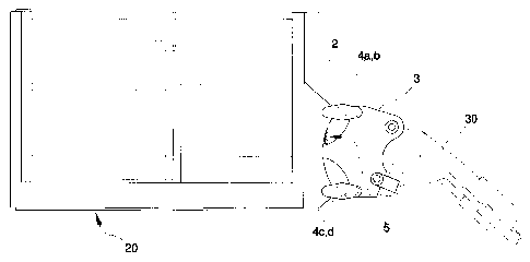
figure 1 is a schematic view of the device of the present invention;
figure 2 is a partially-sectioned view of a detail of the device of figure l
figure 3 is a view from above of a detail of figure 2.

CA 02497016 2005-02-14
-3-
DESCRIPTION of the PREFERRED EMBODLMENTS.
With reference to the figures of the drawings, the device of the present
invention is applicable to a lift work platform comprising a horizontal
support
plane 20 which is predisposed to support a vertical load and is associable to
a
telescopic lift arm 30.
The device comprises a first joint element 2, solidly constrained to the
support
plane 20, and a second joint element 3, associable to a free end of the
telescopic lift arm 30. The device further comprises means for connecting
which are predisposed to connect the first joint element 2 to the second joint
element 3.
The means for connecting are for preventing rotations which change the
relative orientation of the joint elements 2 and 3, so that the first joint
element
2 moves parallel to itself with respect to the second joint element 3.
The means for connecting, predisposed to connect the first joint element 2 to
the second joint element 3, comprise at least two first con rods 4a, 4c,
parallel
to one another and hinged at ends thereof to the first joint element 2 and the
second joint element 3. The first con rods 4a and 4c are hinged about
horizontal and parallel rotation axes in such a way that the first con rods
4a,
4c and the first joint element 2 and the second joint element 3 form between
them a four-bar hinge having a rotation plane on which the first con rods 4a,
4c rotate.
The means for connecting predisposed for connecting the first joint element 2
to the second joint element 3 also comprise at least two second con rods 4b,
4d
which are hinged at ends thereof to the first joint element 2 and the second
joint element 3. Similarly to the first con rods, the second con rods 4b, 4d
are
hinged about horizontal and parallel rotation axes and rotate on a parallel
plane
to the rotation plane of the first con rods 4a, 4c. Each of the two second con

CA 02497016 2005-02-14
-4-
rods 4b, 4d, is arranged parallel to a respective first con rod 4a, 4c and is
connected to said first con rod 4a or 4c by a bar 6, 7 which is perpendicular
to
the rotation plane of the four-bar hinge.
Means for support 5 are interpositioned between the first joint element 2 and
the second joint element 3, which means for support 5 are predisposed,
through elastic means, for supporting the total vertical load on the platform,
which total load is constituted by the weight of the platform itself and the
load
placed upon it.
The means for support 5 comprise at least a first striker 8, solidly
constrained
to the first joint element 2, which striker 8 comprises at least a first flat
surface
8a arranged parallel to the rotation plane of the four-bar hinge. At least a
second striker 9 is solidly constrained to the second joint element 3 and
comprises at least a second flat surface 9a arranged parallel to the rotation
plane of the four-bar hinge. The two flat surfaces 8a, 9a, are arranged
parallel
and one frontally to the other. The elastic means are interpositioned between
the first striker 8 and the second striker 9, in contact with the flat
surfaces 8a,
9a, and deform at least partially due to the effect of the vertical load. The
connection between the first joint element 2 and the second joint element 3,
in
a four-bar hinge arrangement, allows the second joint element 3 to displace,
with respect to the first joint element 2, only according to a circular
trajectory
and without modifying its inclination. In other words, the means for
connecting defined by the first and second con rods do not react to a vertical
load. In this way the vertical load is entirely transmitted to the means for
support 5, independently of its position on the support plane 20. By effect of
the vertical load, the elastic means 12, preferably constituted by a plurality
of
helix springs in parallel alignment, compress proportionally to the entity of
the
vertical load.

CA 02497016 2005-02-14
_5_
Means for detecting are interpositioned between the first joint element 2 and
the second joint element 3, which signal when a predetermined amount of
deformation has occurred in the elastic means.
The means for detecting essentially comprise a rod 10 which at a first end
thereof is constrained to the flat surface 8a of the first striker 8, while a
free
second end faces towards the flat surface of the second striker 9. A switch 11
is solidly mounted on the flat surface of the second striker 9 and is arranged
in a frontal position with respect to the free end of the rod 10. The switch
11
is located at a distance from the free end of the rod 10 so that, if the
vertical
I 0 load acting on the support plane 20 exceeds a predetermined value, the
switch
11 enters into contact with the free end of the rod 10 and generates a
corresponding signal.
The construction of the device is as follows: the first joint element 2
comprises
two walls 2a arranged parallel to the rotation planes of the first con rods
4a, 4c
and the second con rods 4b, 4d. The first con rods 4a, 4c are hinged at a i
first
end thereof to a wall 2a of the first joint element 2. The second con rods 4b,
4d are hinged at a first end thereof to the other wall 2a of the first joint
element
2. The second joint element 3 comprises two walls 3a arranged parallel to the
rotation planes of the first con rods 4a, 4c and the second con rods 4b, 4d.
The
first con rods 4a, 4c are hinged at second ends thereof to a wall 3a of the
second joint element 3. The second con rods 4b, 4d are hinged at second ends
thereof to the other wall 3 a of the second joint element 3 . Each of the
first and
second con rods, 4a, 4b, 4c and 4d is defined by two parallel elements which
are located on opposite sides of the walls 2a, 3a of the first joint element 2
and
the second joint element 3, and are hinged at ends thereof to the walls 2a and
3a.
The device for measuring a vertical load on lifting work platforms of the

CA 02497016 2005-02-14
-6-
invention offers notable advantages.
Firstly, it is extremely simple, economical and reliable. The four-bar hinge
design also enables precise measurement of the load, with no influence of the
vertical load acting on the support plane, thus guaranteeing an absolutely
reliable operation of the work platform. Furthermore the device does not
require predisposition of bearing structures for supporting the support plane,
which avoids any increase in weight of the work plane.

Representative Drawing
A single figure which represents the drawing illustrating the invention.
Administrative Status

2024-08-01:As part of the Next Generation Patents (NGP) transition, the Canadian Patents Database (CPD) now contains a more detailed Event History, which replicates the Event Log of our new back-office solution.

Please note that "Inactive:" events refers to events no longer in use in our new back-office solution.

For a clearer understanding of the status of the application/patent presented on this page, the site Disclaimer , as well as the definitions for Patent , Event History , Maintenance Fee  and Payment History  should be consulted.

Event History

Description Date
Application Not Reinstated by Deadline 2010-02-15
Time Limit for Reversal Expired 2010-02-15
Deemed Abandoned - Failure to Respond to Maintenance Fee Notice 2009-02-16
Application Published (Open to Public Inspection) 2006-02-28
Inactive: Cover page published 2006-02-27
Letter Sent 2005-05-06
Inactive: First IPC assigned 2005-04-01
Inactive: IPC assigned 2005-03-31
Inactive: Single transfer 2005-03-30
Inactive: Courtesy letter - Evidence 2005-03-22
Application Received - Regular National 2005-03-16
Inactive: Filing certificate - No RFE (English) 2005-03-16

Abandonment History

Abandonment Date Reason Reinstatement Date
2009-02-16

Maintenance Fee

The last payment was received on 2008-01-16

Note : If the full payment has not been received on or before the date indicated, a further fee may be required which may be one of the following

  • the reinstatement fee;
  • the late payment fee; or
  • additional fee to reverse deemed expiry.

Patent fees are adjusted on the 1st of January every year. The amounts above are the current amounts if received by December 31 of the current year.
Please refer to the CIPO Patent Fees web page to see all current fee amounts.

Fee History

Fee Type Anniversary Year Due Date Paid Date
Application fee - standard 2005-02-14
Registration of a document 2005-03-30
MF (application, 2nd anniv.) - standard 02 2007-02-14 2007-02-13
MF (application, 3rd anniv.) - standard 03 2008-02-14 2008-01-16
Owners on Record

Note: Records showing the ownership history in alphabetical order.

Current Owners on Record
MANITOU COSTRUZIONI INDUSTRIALI S.R.L.
Past Owners on Record
RICCARDO MAGNI
Past Owners that do not appear in the "Owners on Record" listing will appear in other documentation within the application.
Documents

To view selected files, please enter reCAPTCHA code :


To view images, click a link in the Document Description column. To download the documents, select one or more checkboxes in the first column and then click the "Download Selected in PDF format (Zip Archive)" or the "Download Selected as Single PDF" button.

List of published and non-published patent-specific documents on the CPD .

If you have any difficulty accessing content, you can call the Client Service Centre at 1-866-997-1936 or send them an e-mail at CIPO Client Service Centre.


Document
Description 
Date
(yyyy-mm-dd) 
Number of pages   Size of Image (KB) 
Description 2005-02-13 6 254
Abstract 2005-02-13 1 27
Claims 2005-02-13 3 117
Drawings 2005-02-13 2 39
Representative drawing 2006-01-26 1 8
Filing Certificate (English) 2005-03-15 1 158
Courtesy - Certificate of registration (related document(s)) 2005-05-05 1 104
Reminder of maintenance fee due 2006-10-16 1 110
Courtesy - Abandonment Letter (Maintenance Fee) 2009-04-13 1 172
Reminder - Request for Examination 2009-10-14 1 117
Correspondence 2005-03-15 1 27
Fees 2007-02-12 1 29
Fees 2008-01-15 1 36