Sélection de la langue

Search

Sommaire du brevet 2497016 

Énoncé de désistement de responsabilité concernant l'information provenant de tiers

Une partie des informations de ce site Web a été fournie par des sources externes. Le gouvernement du Canada n'assume aucune responsabilité concernant la précision, l'actualité ou la fiabilité des informations fournies par les sources externes. Les utilisateurs qui désirent employer cette information devraient consulter directement la source des informations. Le contenu fourni par les sources externes n'est pas assujetti aux exigences sur les langues officielles, la protection des renseignements personnels et l'accessibilité.

Disponibilité de l'Abrégé et des Revendications

L'apparition de différences dans le texte et l'image des Revendications et de l'Abrégé dépend du moment auquel le document est publié. Les textes des Revendications et de l'Abrégé sont affichés :

  • lorsque la demande peut être examinée par le public;
  • lorsque le brevet est émis (délivrance).
(12) Demande de brevet: (11) CA 2497016
(54) Titre français: DISPOSITIF POUR MESURER LA CHARGE MAXIMALE PERMISE SUR LES PLATES-FORMES ELEVATRICES
(54) Titre anglais: A DEVICE FOR MEASURING A MAXIMUM LOAD ALLOWED FOR LIFT PLATFORMS
Statut: Réputée abandonnée et au-delà du délai pour le rétablissement - en attente de la réponse à l’avis de communication rejetée
Données bibliographiques
(51) Classification internationale des brevets (CIB):
  • B66F 17/00 (2006.01)
  • G01G 3/00 (2006.01)
  • G01G 19/14 (2006.01)
(72) Inventeurs :
  • MAGNI, RICCARDO (Italie)
(73) Titulaires :
  • MANITOU COSTRUZIONI INDUSTRIALI S.R.L.
(71) Demandeurs :
  • MANITOU COSTRUZIONI INDUSTRIALI S.R.L. (Italie)
(74) Agent: SMART & BIGGAR LP
(74) Co-agent:
(45) Délivré:
(22) Date de dépôt: 2005-02-14
(41) Mise à la disponibilité du public: 2006-02-28
Licence disponible: S.O.
Cédé au domaine public: S.O.
(25) Langue des documents déposés: Anglais

Traité de coopération en matière de brevets (PCT): Non

(30) Données de priorité de la demande:
Numéro de la demande Pays / territoire Date
MO2004A000217 (Italie) 2004-08-31

Abrégés

Abrégé anglais


A raisable work platform comprises a horizontal support plane which is
predisposed to support a vertical load and is associable to a telescopic lift
arm.
The device comprises: a first joint element, solidly constrained to the
support
plane; a second joint element, associable to a free end of the telescopic lift
arm.
Means for connecting, predisposed to connect the first joint element to the
second joint element, enable the joint elements to translate only relatively.
Means for supporting, interpositioned between the first joint element and the
second joint element, are predisposed for supporting the total vertical load
of
the platform, constituted by the weight of the platform itself and the load
borne
thereon, through elastic means. Means for measuring are associated to the
means for supporting, which means for measuring signal a reaching of a
predetermined deformation of the elastic means.

Revendications

Note : Les revendications sont présentées dans la langue officielle dans laquelle elles ont été soumises.


-7-
WHAT is CLAIMED.
1). A device for measuring a maximum load allowed for lift platforms, in
which a raisable work platform comprises a horizontal support plane which is
predisposed to support a vertical load and is associable to a telescopic lift
arm,
comprising: a first joint element, solidly constrained to the support plane; a
second joint element, associable to a free end of the telescopic lift arm;
means
for connecting, predisposed to connect the first joint element to the second
joint element, for preventing rotations which change a relative orientation of
the joint elements; means for supporting, interpositioned between the first
joint
element and the second joint element and predisposed for supporting the total
vertical load of the platform through elastic means; means for measuring being
associated to the means for supporting, which means for measuring signal a
reaching of a predetermined deformation of the elastic means.
2). The device of claim 1, wherein the means for connecting, predisposed to
connect the first joint element to the second joint element, comprise at least
two first con rods, parallel to one another and hinged at ends thereof to the
first
joint element and the second joint element about horizontal and parallel
rotation axes, in such a way that the first con rods and the first joint
element
and t:he second joint element form between them a four-bar hinge having a
rotation plane on which the first con rods rotate.
3). The device of claim 2, wherein it comprises at least two second con rods
which are hinged at ends thereof to the first joint element and to the second
joint element about horizontal and parallel rotation axes, the second con rods


-8-
rotating on a parallel plane to the rotation plane of the first con rods, each
of
which two second con rods is arranged parallel to a respective first con rod
and
is also connected to the respective first con rod by means of a bar which is
perpendicular to a rotation plane of the four-bar hinge.
4). The device of claim 1, wherein the means for supporting comprise: at least
a first striker, solidly constrained to the first joint element, which first
striker
8 comprises at least a first flat surface arranged parallel to the rotation
plane
of the four-bar hinge; at least a second striker, solidly constrained to the
second joint element, which comprises at least a second flat surface arranged
perpendicular to the rotation plane of the four-bar hinge; the elastic means
being interpositioned between the first striker and the second striker, and
being
in contact with the first and second flat surfaces, and deforming at least
partially due to an effect of a vertical load.
5). The device of claims 1 or 4, wherein the means for detecting for
signalling
a reaching of a predetermined amount of deformation of the elastic means
comprise: a rod which at a first end thereof is constrained to the first flat
surface of the first striker and at a free second end thereof is facing the
second
flat surface of the second striker; a switch being solidly mounted on the
second
flat surface of the second striker and arranged in a frontal position with
respect
to the free second end of the rod at a distance therefrom which is such that
if
the vertical load acting on the support plane exceeds a predetermined value,
the
switch enters into contact with the free second end of the rod, and generates
a signal.
6). The device of any one of the preceding claims, wherein the first joint
element comprises two walls arranged parallel to the rotation planes of the
first
con rods and the second con rods, the first con rods being hinged at first
ends
thereof to a first wallof the first joint element, the second con rods being


-9-
hinged at first ends thereof to another wall of the first joint element.
7). The device of any one of the preceding claims, wherein the second joint
element comprises two walls arranged parallel to the rotation planes of the
first con rods and the second con rods, the first con rods being hinged at
second ends thereof to a first wall of the second joint element, the second
con
rods being hinged at second ends thereof to another wall of the second joint
element.
8). The device of any one of the preceding claims, wherein each of the first
con rods and the second con rods is defined by two parallel elements located
on opposite sides with respect to the walls of the first joint element and the
second joint element, the two parallel elements being hinged at ends thereof
to
the walls.

Description

Note : Les descriptions sont présentées dans la langue officielle dans laquelle elles ont été soumises.

CA 02497016 2005-02-14
A DEVICE FOR MEASURING A MAXIMUM LOAD ALLOWED FOR LIFT
PLATFORMS.
BACKGROUND of the INVENTION.
The device is usefully applied in lift platforms of a type in which a
horizontal
support is predisposed for supporting a vertical load and is associable to a
telescopic lift arm. The horizontal platform can be provided with lateral
barriers and support, for example, an operator having equipment which is to
be lifted to determined heights for performing operations on apparatus located
above ground level.
Various existing standards demand that work platforms be provided with
devices for measuring the vertical load acting on the support plane. If the
load
exceeds a certain safety value, safety means intervene for blocking the
l0 platform.
Prior-art devices for measuring vertical load generally comprise a bearing
structure, associated to a telescopic arm, which inferiorly supports the work
platform. Means for measuring the vertical load are interpositioned between
the bearing structure and the platform.
Devices of this type exhibit drawbacks constituted by the considerable
additional mass due to the bearing structure itself as well as the difftculty
of
realising a bearing structure which is sufficiently rigid not to deform by
effect
of the vertical load, compromising the accuracy of the measurement.
Other known-type devices comprise strain-gauge cells associated to the pivot
2o or pivots which connect the work platform to the extensible arm. The
devices
of this type exhibit the considerable drawback of being sensitive to the
position
of the load on the work platform, i.e. to the torque generated by the vertical

CA 02497016 2005-02-14
load with respect to the attachment point of the platform, and as a result the
measurement taken and provided does not entirely depend on the entity of the
vertical load.
The main aim of the present invention is to provide a device for measuring the
vertical load in liftable work platforms, which enables the drawbacks of the
prior art to be overcome.
SUMMARY of the INVENTLON.
A rai.sable work platform comprises a horizontal support plane which is
predisposed to support a vertical load and is associable to a telescopic lift
arm.
The device comprises: a first joint element, solidly constrained to the
support
plane; a second joint element, associable to a free end of the telescopic lift
arm.
Means for connecting, predisposed to connect the first joint element to the
second joint element, enable the joint elements to translate only relatively.
Means for supporting, interpositioned between the first joint element and the
IS second joint element, are predisposed for supporting the total vertical
load of
the platform, constituted by the weight of the platform itself and the load
borne
thereon, through elastic means. Means for measuring are associated to the
means for supporting, which means for measuring signal a reaching of a
predetermined deformation of the elastic means.
BRIEF DESCRIPTION of the DRAWINGS.
Further characteristics and advantages of the present invention will better
emerge from the detailed description that follows, illustrated purely by way
of
a non-limiting example in the accompanying figures of the drawings, in which:
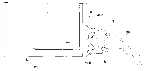
figure 1 is a schematic view of the device of the present invention;
figure 2 is a partially-sectioned view of a detail of the device of figure l
figure 3 is a view from above of a detail of figure 2.

CA 02497016 2005-02-14
-3-
DESCRIPTION of the PREFERRED EMBODLMENTS.
With reference to the figures of the drawings, the device of the present
invention is applicable to a lift work platform comprising a horizontal
support
plane 20 which is predisposed to support a vertical load and is associable to
a
telescopic lift arm 30.
The device comprises a first joint element 2, solidly constrained to the
support
plane 20, and a second joint element 3, associable to a free end of the
telescopic lift arm 30. The device further comprises means for connecting
which are predisposed to connect the first joint element 2 to the second joint
element 3.
The means for connecting are for preventing rotations which change the
relative orientation of the joint elements 2 and 3, so that the first joint
element
2 moves parallel to itself with respect to the second joint element 3.
The means for connecting, predisposed to connect the first joint element 2 to
the second joint element 3, comprise at least two first con rods 4a, 4c,
parallel
to one another and hinged at ends thereof to the first joint element 2 and the
second joint element 3. The first con rods 4a and 4c are hinged about
horizontal and parallel rotation axes in such a way that the first con rods
4a,
4c and the first joint element 2 and the second joint element 3 form between
them a four-bar hinge having a rotation plane on which the first con rods 4a,
4c rotate.
The means for connecting predisposed for connecting the first joint element 2
to the second joint element 3 also comprise at least two second con rods 4b,
4d
which are hinged at ends thereof to the first joint element 2 and the second
joint element 3. Similarly to the first con rods, the second con rods 4b, 4d
are
hinged about horizontal and parallel rotation axes and rotate on a parallel
plane
to the rotation plane of the first con rods 4a, 4c. Each of the two second con

CA 02497016 2005-02-14
-4-
rods 4b, 4d, is arranged parallel to a respective first con rod 4a, 4c and is
connected to said first con rod 4a or 4c by a bar 6, 7 which is perpendicular
to
the rotation plane of the four-bar hinge.
Means for support 5 are interpositioned between the first joint element 2 and
the second joint element 3, which means for support 5 are predisposed,
through elastic means, for supporting the total vertical load on the platform,
which total load is constituted by the weight of the platform itself and the
load
placed upon it.
The means for support 5 comprise at least a first striker 8, solidly
constrained
to the first joint element 2, which striker 8 comprises at least a first flat
surface
8a arranged parallel to the rotation plane of the four-bar hinge. At least a
second striker 9 is solidly constrained to the second joint element 3 and
comprises at least a second flat surface 9a arranged parallel to the rotation
plane of the four-bar hinge. The two flat surfaces 8a, 9a, are arranged
parallel
and one frontally to the other. The elastic means are interpositioned between
the first striker 8 and the second striker 9, in contact with the flat
surfaces 8a,
9a, and deform at least partially due to the effect of the vertical load. The
connection between the first joint element 2 and the second joint element 3,
in
a four-bar hinge arrangement, allows the second joint element 3 to displace,
with respect to the first joint element 2, only according to a circular
trajectory
and without modifying its inclination. In other words, the means for
connecting defined by the first and second con rods do not react to a vertical
load. In this way the vertical load is entirely transmitted to the means for
support 5, independently of its position on the support plane 20. By effect of
the vertical load, the elastic means 12, preferably constituted by a plurality
of
helix springs in parallel alignment, compress proportionally to the entity of
the
vertical load.

CA 02497016 2005-02-14
_5_
Means for detecting are interpositioned between the first joint element 2 and
the second joint element 3, which signal when a predetermined amount of
deformation has occurred in the elastic means.
The means for detecting essentially comprise a rod 10 which at a first end
thereof is constrained to the flat surface 8a of the first striker 8, while a
free
second end faces towards the flat surface of the second striker 9. A switch 11
is solidly mounted on the flat surface of the second striker 9 and is arranged
in a frontal position with respect to the free end of the rod 10. The switch
11
is located at a distance from the free end of the rod 10 so that, if the
vertical
I 0 load acting on the support plane 20 exceeds a predetermined value, the
switch
11 enters into contact with the free end of the rod 10 and generates a
corresponding signal.
The construction of the device is as follows: the first joint element 2
comprises
two walls 2a arranged parallel to the rotation planes of the first con rods
4a, 4c
and the second con rods 4b, 4d. The first con rods 4a, 4c are hinged at a i
first
end thereof to a wall 2a of the first joint element 2. The second con rods 4b,
4d are hinged at a first end thereof to the other wall 2a of the first joint
element
2. The second joint element 3 comprises two walls 3a arranged parallel to the
rotation planes of the first con rods 4a, 4c and the second con rods 4b, 4d.
The
first con rods 4a, 4c are hinged at second ends thereof to a wall 3a of the
second joint element 3. The second con rods 4b, 4d are hinged at second ends
thereof to the other wall 3 a of the second joint element 3 . Each of the
first and
second con rods, 4a, 4b, 4c and 4d is defined by two parallel elements which
are located on opposite sides of the walls 2a, 3a of the first joint element 2
and
the second joint element 3, and are hinged at ends thereof to the walls 2a and
3a.
The device for measuring a vertical load on lifting work platforms of the

CA 02497016 2005-02-14
-6-
invention offers notable advantages.
Firstly, it is extremely simple, economical and reliable. The four-bar hinge
design also enables precise measurement of the load, with no influence of the
vertical load acting on the support plane, thus guaranteeing an absolutely
reliable operation of the work platform. Furthermore the device does not
require predisposition of bearing structures for supporting the support plane,
which avoids any increase in weight of the work plane.

Dessin représentatif
Une figure unique qui représente un dessin illustrant l'invention.
États administratifs

2024-08-01 : Dans le cadre de la transition vers les Brevets de nouvelle génération (BNG), la base de données sur les brevets canadiens (BDBC) contient désormais un Historique d'événement plus détaillé, qui reproduit le Journal des événements de notre nouvelle solution interne.

Veuillez noter que les événements débutant par « Inactive : » se réfèrent à des événements qui ne sont plus utilisés dans notre nouvelle solution interne.

Pour une meilleure compréhension de l'état de la demande ou brevet qui figure sur cette page, la rubrique Mise en garde , et les descriptions de Brevet , Historique d'événement , Taxes périodiques et Historique des paiements devraient être consultées.

Historique d'événement

Description Date
Demande non rétablie avant l'échéance 2010-02-15
Le délai pour l'annulation est expiré 2010-02-15
Réputée abandonnée - omission de répondre à un avis sur les taxes pour le maintien en état 2009-02-16
Demande publiée (accessible au public) 2006-02-28
Inactive : Page couverture publiée 2006-02-27
Lettre envoyée 2005-05-06
Inactive : CIB en 1re position 2005-04-01
Inactive : CIB attribuée 2005-03-31
Inactive : Transfert individuel 2005-03-30
Inactive : Lettre de courtoisie - Preuve 2005-03-22
Demande reçue - nationale ordinaire 2005-03-16
Exigences de dépôt - jugé conforme 2005-03-16
Inactive : Certificat de dépôt - Sans RE (Anglais) 2005-03-16

Historique d'abandonnement

Date d'abandonnement Raison Date de rétablissement
2009-02-16

Taxes périodiques

Le dernier paiement a été reçu le 2008-01-16

Avis : Si le paiement en totalité n'a pas été reçu au plus tard à la date indiquée, une taxe supplémentaire peut être imposée, soit une des taxes suivantes :

  • taxe de rétablissement ;
  • taxe pour paiement en souffrance ; ou
  • taxe additionnelle pour le renversement d'une péremption réputée.

Veuillez vous référer à la page web des taxes sur les brevets de l'OPIC pour voir tous les montants actuels des taxes.

Historique des taxes

Type de taxes Anniversaire Échéance Date payée
Taxe pour le dépôt - générale 2005-02-14
Enregistrement d'un document 2005-03-30
TM (demande, 2e anniv.) - générale 02 2007-02-14 2007-02-13
TM (demande, 3e anniv.) - générale 03 2008-02-14 2008-01-16
Titulaires au dossier

Les titulaires actuels et antérieures au dossier sont affichés en ordre alphabétique.

Titulaires actuels au dossier
MANITOU COSTRUZIONI INDUSTRIALI S.R.L.
Titulaires antérieures au dossier
RICCARDO MAGNI
Les propriétaires antérieurs qui ne figurent pas dans la liste des « Propriétaires au dossier » apparaîtront dans d'autres documents au dossier.
Documents

Pour visionner les fichiers sélectionnés, entrer le code reCAPTCHA :


Pour visualiser une image, cliquer sur un lien dans la colonne description du document. Pour télécharger l'image (les images), cliquer l'une ou plusieurs cases à cocher dans la première colonne et ensuite cliquer sur le bouton "Télécharger sélection en format PDF (archive Zip)" ou le bouton "Télécharger sélection (en un fichier PDF fusionné)".

Liste des documents de brevet publiés et non publiés sur la BDBC .

Si vous avez des difficultés à accéder au contenu, veuillez communiquer avec le Centre de services à la clientèle au 1-866-997-1936, ou envoyer un courriel au Centre de service à la clientèle de l'OPIC.


Description du
Document 
Date
(aaaa-mm-jj) 
Nombre de pages   Taille de l'image (Ko) 
Description 2005-02-14 6 254
Abrégé 2005-02-14 1 27
Revendications 2005-02-14 3 117
Dessins 2005-02-14 2 39
Dessin représentatif 2006-01-27 1 8
Page couverture 2006-02-07 1 42
Certificat de dépôt (anglais) 2005-03-16 1 158
Courtoisie - Certificat d'enregistrement (document(s) connexe(s)) 2005-05-06 1 104
Rappel de taxe de maintien due 2006-10-17 1 110
Courtoisie - Lettre d'abandon (taxe de maintien en état) 2009-04-14 1 172
Rappel - requête d'examen 2009-10-15 1 117
Correspondance 2005-03-16 1 27
Taxes 2007-02-13 1 29
Taxes 2008-01-16 1 36