Language selection

Search

Patent 2497375 Summary

Third-party information liability

Some of the information on this Web page has been provided by external sources. The Government of Canada is not responsible for the accuracy, reliability or currency of the information supplied by external sources. Users wishing to rely upon this information should consult directly with the source of the information. Content provided by external sources is not subject to official languages, privacy and accessibility requirements.

Claims and Abstract availability

Any discrepancies in the text and image of the Claims and Abstract are due to differing posting times. Text of the Claims and Abstract are posted:

  • At the time the application is open to public inspection;
  • At the time of issue of the patent (grant).
(12) Patent: (11) CA 2497375
(54) English Title: SOLAR POWERED HEAT TRACE SYSTEM
(54) French Title: SYSTEME SOLAIRE A CABLES CHAUFFANTS
Status: Granted
Bibliographic Data
(51) International Patent Classification (IPC):
  • H05B 3/00 (2006.01)
  • H02S 10/20 (2014.01)
  • H02S 99/00 (2014.01)
(72) Inventors :
  • SQUIRE, CURTIS (Canada)
(73) Owners :
  • SQUIRE, CURTIS (Canada)
(71) Applicants :
  • SQUIRE, CURTIS (Canada)
  • SQUIRE, CURTIS (Canada)
(74) Agent: WOODRUFF, NATHAN V.
(74) Associate agent:
(45) Issued: 2014-02-04
(22) Filed Date: 2005-02-17
(41) Open to Public Inspection: 2006-08-17
Examination requested: 2010-02-16
Availability of licence: N/A
(25) Language of filing: English

Patent Cooperation Treaty (PCT): No

(30) Application Priority Data: None

Abstracts

English Abstract

A solar powered heat trace system includes a heat trace system and a photovoltaic panel. The heat trace system is rated for use with alternating current at a specified alternating current voltage with a specified watts per foot of heat output. The photovoltaic panel is capable of converting sunlight into direct current electric power. Direct current is supplied from the photovoltaic panel to the heat trace system at a direct current voltage which is substantially equivalent to the specified alternative current voltage and produces heat within the specified watts per foot heat output for which the heat trace system is rated.


French Abstract

Un système de traçage thermique à énergie solaire comprend un système de traçage thermique et un panneau photovoltaïque. Le système de traçage thermique est conçu pour être alimenté par un courant alternatif à une tension de courant alternatif spécifiée avec une puissance calorifique en watts par pied spécifiée. Le panneau photovoltaïque est en mesure de convertir la lumière du soleil en un courant électrique continu. Le courant continu est fourni par le panneau photovoltaïque au système de traçage thermique à une tension de courant direct qui est essentiellement équivalente à la tension de courant alternatif spécifiée et produit de la chaleur en fonction de la puissance calorifique en watts par pied spécifiée pour laquelle le système de traçage thermique est conçu.

Claims

Note: Claims are shown in the official language in which they were submitted.


5
What is Claimed is:

1. A solar powered heat trace system, comprising:
a heat trace system rated for use with alternating current at a specified
alternating
current voltage with a specified watts per foot of heat output;
a photovoltaic panel capable of converting sunlight into direct current
electric power;
and
a battery that is charged by the photovoltaic panel and that supplies direct
current to
the heat trace system at a direct current voltage which is substantially
equivalent to the
specified alternative current voltage and produces heat within the specified
watts per foot heat
output for which the heat trace system is rated.
2. The solar powered heat trace system as defined in Claim 1, wherein the heat
trace system
is rated for 120 volts alternating current with a heat output of 20 watts per
foot and the
equivalent direct current voltage is approximately 48 volts, producing about 7
watts per foot.
3. A method comprising the steps of:
providing a battery that is charged by a photovoltaic panel; and
using the battery to provide direct current to a heat trace system rated for
use with
alternating current at a specified alternating current voltage with a
specified watts per foot of
heat output, the direct current being supplied at a direct current voltage
which is substantially
equivalent to the specified alternative current voltage and produces heat
within the specified
watts per foot heat output for which the heat trace system is rated.

Description

Note: Descriptions are shown in the official language in which they were submitted.


CA 02497375 2005-02-17
1
TITLE OF THE INVENTION:
Solar Powered Heat Trace System
FIELD OF THE INVENTION
The present invention relates to a solar powered heat trace system.
BACKGROUND OF THE INVENTION
There is a need for heat trace systems at remote locations, such as well
sites, to
prevent pipes from freezing. Heat trace systems are made for use with
alternating current.
Solar power generating systems produce direct current. In order to use heat
trace systems
with solar power, the direct current produced must be converted to alternating
current.
Unfortunately, the use of inverters which change direct current to alternating
current produce
unacceptable losses.
SUMMARY OF THE INVENTION
According to the present invention there is provided a solar powered heat
trace system
which includes a heat trace system and a photovoltaic panel. The heat trace
system is rated
for use with alternating current at a specified alternating current voltage
with a specified watts
per foot of heat output. The photovoltaic panel is capable of converting
sunlight into direct
2 0 current electric power. Direct current is supplied from the photovoltaic
panel to the heat trace
system at a direct current voltage, which is substantially equivalent to the
specified alternative
current voltage and produces heat within the specified watts per foot heat
output for which the
heat trace system is rated.
2 5 BRIEF DESCRIPTION OF THE DRAWINGS
These and other features of the invention will become more apparent from the
following description in which reference is made to the appended drawings, the
drawings are
for the purpose of illustration only and are not intended to in any way limit
the scope of the
invention to the particular embodiment or embodiments shown, wherein:
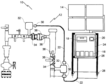
30 FIG. 1 is a side elevation view of a solar powered heat trace system
constructed in
accordance with the teachings of the present invention.
FIG. 2 is a schematic diagram of the solar powered heat trace system
illustrated in


CA 02497375 2005-02-17
2
FIG.1.
DETAILED DESCRIPTION OF THE PREFERRED EMBODIMENT
The preferred embodiment, a solar powered heat trace system generally
identified by
reference numeral 10, will now be described with reference to FIG.1 and FIG.
2.
Structure and Relationship of Parts:
Referring to FIG. 1, there is shown solar powered heat trace system 10
including a
heat trace system indicated generally by reference numeral 12 rated for use
with alternating
1 o current at a specified alternating current voltage with a specified watts
per foot of heat output.
For example, heat trace system 12 may be rated for 120 volts alternating
current (VAC) with
a heat output of 20 watts per foot. Heat trace system 12 is powered by a
photovoltaic panels
14 capable of converting sunlight into direct current electric power. As
shown, a bank of four
photovoltaic panels 14 are shown connected in series, and are used to charge a
bank of four
batteries 16 connected in series, such as 120 Amp/Hour batteries. Batteries 16
are charged
via a charge regulator 18. Direct current is then supplied from photovoltaic
panel 14 to heat
trace system 12 at a direct current voltage (VDC) that is substantially
equivalent to the
specified alternative current voltage and produces heat within the specifted
watts per foot heat
output for which the heat trace system is rated. In the example heat trace
system 12 described
2 0 above, the equivalent direct current voltage would be approximately 48
VDC. This is done
using a multi-function timing relay 20, such as a 48 VDC timing relay, that
will oscillate the
load to maintain a fifty percent duty cycle. The 48 VDC is then carried to
heat trace system
12 by conductor 22, such as a # 14 gauge, 2 conductor teck cable. Conductors
22 are
connected to the power connection kit 32 of heat trace system 12 by connectors
30 that
2 5 provide a grounded, dust-free and water-tight connection. A water-tight
foam and foil
insulated enclosure 24 is used to guarantee a secure atmosphere for the
components within.
Enclosure 24 and photovoltaic panels 14 are supported by a stand 26, which
includes stakes
28 to stabilize the unit against adverse conditions such as wind.
3 0 Heat trace system 12 includes power connection kit 32 and a heat trace 34.
An
example is a 120 VAC 20 watts/foot heat trace that produces approximately 7
watts/foot of
heat when connected to 48 VDC without insulation. In addition, there is a
terminal end kit 36


CA 02497375 2005-02-17
3
that insulates heat trace 34 from ground and the weather. As depicted, there
are two heat
traces 32, two power connection kits 32, and another conductor 22 connecting
power
connection kits 32 via connectors 30.
Referring to FIG. 2, there is shown a sample circuit diagram of solar powered
heat
trace system 10. Other components, such as fuses 33 may be included.
Using the example specifications given above, it has been found that the
maximum
heat trace that can be connected is a 5' length, or two separate lengths that
equal 5'. Loading
beyond this limit causes the system to fail after about 14 short, cold winter
days. It will be
understood that larger systems may be constructed to support greater loads as
necessary,
however, it is believed that the apparatus described above is adequate for
common uses.
Operation:
The use and operation of solar powered heat trace system 10 will now be
discussed
with reference to FIGS. 1 and 2. The various parts are arranged as shown in
FIG. 1 and
connected as shown in FIG. 2. Referring now to FIG. 1, photovoltaic panels 14
are used to
charge batteries 16 via charge regulator 18. Timing relay 20 oscillates the
load to maintain a
fifty percent duty cycle, and conductor 22 carries the current to heat trace
system 12.
2 0 Connectors 30 are used to connect conductors 22 to power connection kit
32. Heat trace 34 is
used to prevent freezing of gas field components 38, such as valves located
just below the
flowline.
There has been reference in the description to a duty cycle. It will be
apparent to one
2 5 skilled in the art that the use of a duty cycle is not required. It could
be run 24 hours a day on
direct current. The use of a duty cycle reduces the size requirements for the
battery pack and
the solar panel. For a heat tracing application, 24 hour operation would far
exceed the needs
for the application. The duty cycle selected can vary. Beneficial results have
been obtained
with a duty cycle that involves one hour on and one hour off. It will be
appreciated that this
3 0 duty cycle has been arbitrarily selected and that the time interval can be
either increased or
shortened.


CA 02497375 2005-02-17
4
In this patent document, the word "comprising" is used in its non-limiting
sense to
mean that items following the word are included, but items not specifically
mentioned are not
excluded. A reference to an element by the indefinite article "a" does not
exclude the
possibility that more than one of the element is present, unless the context
clearly requires that
there be one and only one of the elements.
It will be apparent to one skilled in the art that modifications may be made
to the
illustrated embodiment without departing from the spirit and scope of the
invention as
hereinafter defined in the Claims.

Representative Drawing
A single figure which represents the drawing illustrating the invention.
Administrative Status

For a clearer understanding of the status of the application/patent presented on this page, the site Disclaimer , as well as the definitions for Patent , Administrative Status , Maintenance Fee  and Payment History  should be consulted.

Administrative Status

Title Date
Forecasted Issue Date 2014-02-04
(22) Filed 2005-02-17
(41) Open to Public Inspection 2006-08-17
Examination Requested 2010-02-16
(45) Issued 2014-02-04

Abandonment History

There is no abandonment history.

Payment History

Fee Type Anniversary Year Due Date Amount Paid Paid Date
Application Fee $200.00 2005-02-17
Maintenance Fee - Application - New Act 2 2007-02-19 $50.00 2007-01-15
Maintenance Fee - Application - New Act 3 2008-02-18 $50.00 2008-01-24
Maintenance Fee - Application - New Act 4 2009-02-17 $50.00 2008-12-04
Maintenance Fee - Application - New Act 5 2010-02-17 $100.00 2010-02-04
Request for Examination $400.00 2010-02-16
Maintenance Fee - Application - New Act 6 2011-02-17 $100.00 2011-01-27
Maintenance Fee - Application - New Act 7 2012-02-17 $100.00 2011-12-06
Maintenance Fee - Application - New Act 8 2013-02-18 $100.00 2013-01-03
Final Fee $150.00 2013-11-18
Maintenance Fee - Patent - New Act 9 2014-02-17 $100.00 2014-02-13
Maintenance Fee - Patent - New Act 10 2015-02-17 $125.00 2015-01-26
Maintenance Fee - Patent - New Act 11 2016-02-17 $125.00 2016-01-26
Maintenance Fee - Patent - New Act 12 2017-02-17 $125.00 2017-01-04
Maintenance Fee - Patent - New Act 13 2018-02-19 $125.00 2018-01-29
Maintenance Fee - Patent - New Act 14 2019-02-18 $125.00 2019-02-15
Maintenance Fee - Patent - New Act 15 2020-02-17 $225.00 2020-02-13
Maintenance Fee - Patent - New Act 16 2021-02-17 $229.50 2021-02-11
Maintenance Fee - Patent - New Act 17 2022-02-17 $229.04 2022-02-17
Maintenance Fee - Patent - New Act 18 2023-02-17 $236.83 2023-02-16
Maintenance Fee - Patent - New Act 19 2024-02-19 $253.00 2024-02-15
Owners on Record

Note: Records showing the ownership history in alphabetical order.

Current Owners on Record
SQUIRE, CURTIS
Past Owners on Record
None
Past Owners that do not appear in the "Owners on Record" listing will appear in other documentation within the application.
Documents

To view selected files, please enter reCAPTCHA code :


To view images, click a link in the Document Description column. To download the documents, select one or more checkboxes in the first column and then click the "Download Selected in PDF format (Zip Archive)" or the "Download Selected as Single PDF" button.

List of published and non-published patent-specific documents on the CPD .

If you have any difficulty accessing content, you can call the Client Service Centre at 1-866-997-1936 or send them an e-mail at CIPO Client Service Centre.


Document
Description 
Date
(yyyy-mm-dd) 
Number of pages   Size of Image (KB) 
Maintenance Fee Payment 2022-02-17 1 33
Abstract 2005-02-17 1 17
Description 2005-02-17 4 165
Claims 2005-02-17 1 32
Drawings 2005-02-17 2 46
Representative Drawing 2006-07-26 1 10
Cover Page 2006-08-04 1 37
Claims 2013-06-05 1 30
Cover Page 2014-01-09 2 40
Prosecution-Amendment 2010-02-16 1 28
Correspondence 2010-03-03 1 89
Correspondence 2011-04-27 1 12
Correspondence 2011-04-27 1 19
Correspondence 2005-03-21 1 72
Assignment 2005-02-17 3 86
Correspondence 2006-10-18 1 40
Fees 2007-01-15 1 25
Fees 2008-01-24 2 70
Correspondence 2008-01-24 2 70
Fees 2008-12-04 1 29
Correspondence 2009-10-20 1 24
Fees 2010-02-04 1 27
Fees 2011-01-27 1 201
Correspondence 2011-03-31 3 165
Maintenance Fee Payment 2019-02-15 1 33
Prosecution-Amendment 2013-02-11 2 69
Prosecution-Amendment 2013-06-05 5 96
Correspondence 2013-11-18 1 33
Maintenance Fee Payment 2024-02-15 1 33
Fees 2015-01-26 1 33