Note: Descriptions are shown in the official language in which they were submitted.
CA 02497607 2005-02-18
DOPPLER ULTRASONIC FLOWMETER, PROCESSOR
AND COMPUTER READABLE MEDIUM FOR THE SAME
Field of the Invention
The present invention relates to the field of fluid flow
measurement and in particular to a Doppler ultrasonic
flowmeter.
Background
A clamp-on ultrasonic flowmeter is a flowmeter of a
type for measuring, from outside of a tubular body
exemplified by a water pipe, the flow velocity and the flow
rate of a fluid that flows inside of the tubular body using
an ultrasonic transducer (module for transmitting/receiving
ultrasonic pulses of arbitrary frequency) attached to a part
of the outer surface of the tubular body. Clamp-on
ultrasonic flowmeters can be roughly classified into transit
time types and Doppler types.
The transit time type employ a method in which
ultrasonic waves are made to go back and forth on a path
that crosses diagonally over a fluid flowing inside of a
tubular body, and the flow rate of the fluid is measured
from a difference of time taken for the ultrasonic waves to
transit the outward path and the return path, respectively.
1
CA 02497607 2005-02-18
On the other hand, the Doppler type employ a method
in which suspended particles (such as air bubbles or others)
included in a fluid are presumed to move at the same speed
as the f luid, and the f low rate of the fluid is measured f rom
the moving speed of the suspended particles. Due to the
fact that, during transmission of ultrasonic waves into
the fluid, the frequency of the ultrasonic waves reflected
by the suspended particles is changed by the Doppler
effect, the flow velocity of the fluid can be calculated
based on the resulting frequency shift and the flow rate of
the fluid can be calculated by subjecting the flow
velocity distribution to an integration computation.
Such a conventional technology for the Doppler
ultrasonic flowmeter is disclosed in Japanese Patent
Application Publication No. 2000097742A (hereinafter Patent
Document 1), for example. Patent Document 1 proposes a
Doppler ultrasonic flowmeter such that high-precision
measurement is possible without touching a fluid in the
unsteady state. In the invention of Patent Document 1,
ultrasonic pulses (a group thereof) are transmitted toward
a measurement fluid subject at required intervals, and
ultrasonic echoes as a result of reflection on a reflector
located on the measurement line are received. Based
thereon, a Doppler shift (i.e. a frequency shift or change
2
CA 02497607 2005-02-18
of frequency) is calculated so that a flow velocity
distribution is derived for the measurement fluid subject.
Based on the resulting flow velocity distribution, the
flow rate is derived by integration computation, whereby
flow rate measurement is achieved.
Referring now to FIG. 6, the flow velocity
distribution and flow rate computation will both be
described.
In FIG. 6, a group of reflection echoes indicated by
(1) in the drawing are reflection echoes with respect to a
specific transmission pulse, and a group of reflection
echoes indicated by (2) in the drawing are reflection
echoes with respect to another pulse that is transmitted
successively to the transmission pulse. In FIG. 6, Ot
denotes a repetition period (pulse repetition period T) of
the transmission pulse. The reflection echoes partially
show a large amplitude at parts A and B. Part A indicates
the reflection echoes as a result of reflection on an
entrance wall of the tube, and part B indicates reflection
echoes as a result of reflection on the opposite wall of
the tube. The part between A and B indicates the part along
the measurement line (i.e. the travel path of the
ultrasonic waves) inside of the tube. By measuring the
amount of Doppler shift in the reflection echoes at
3
CA 02497607 2005-02-18
positions between parts A and B, the flow velocity of
the fluid can be measured at the respective positions on
the measurement line. In this manner, calculating the flow
velocity at the respective positions can successfully
lead to the flow velocity distribution as shown in the
drawing, for example.
Note here that the flow velocity distribution can be
derived by repeatedly executing, tens and hundreds of
times, the process of calculating the flow velocity
based on the received reflection echoes. Note also here
that the measurement line has an angle of 8f with respect
to the normal to the tube pipe axis, and that the
positions on the measurement line are converted into the
positions on the cross section of the tube using the angle 6f .
The flow velocity distribution derived as such is then
subjected to an integration process so that the flow
rate can be calculated. The integration process is
executed not using the flow velocity distribution in its
entirety, but the integration process is executed using the
flow velocity distribution of the integration range as
shown in the drawing. For example, the integration range is
a range from the center of the tube (tube axis) to the opposite
wall.
4
CA 02497607 2005-02-18
Moreover, the specific position on the above-described
measurement line (on the cross section of the pipe) is
referred to as a channel. In other words, any arbitrary
area of the measurement line is divided into an arbitrary
number of sections, and each section is referred to as a
channel. For example, in a case where the division number
is 50, it means that there are 50 channels (this division
number relates to spatial resolution). The above-described
flow velocity is thus derived on the basis of the
channel, and the points of the flow velocity distribution
shown in FIG. 6 respectively represent the channel position
and the flow velocity thereof.
The sound velocity or the distance for the ultrasonic
waves to travel in the tube wall or in the fluid is known in
advance. Thus, based on these, in the reflection echo
waveform shown in FIG. 6, it is possible to calculate in
advance the correspondence between data timing and a
channel position. To be specific, the time taken for
transmission and reception can be calculated in advance
for each of the channel positions on the cross section of
the tube, and a derived correspondence between the channel
position and the time can be stored.
5
CA 02497607 2005-02-18
Summary of the Invention
As described above, the flow velocity distribution is
used as a basis to calculate the flow rate through an
integration process. Therefore, the integration range
has a large influence over the measurement precision for
the flow rate. In spite of this fact, a quantization error
generally occurs in spatial resolution, and thus an
integration error does occur, resulting in a measurement
error.
An object of the present invention is to provide a
Doppler ultrasonic flowmeter that achieves flow rate
measurement with a high precision by calculating the flow
rate using a flow rate calculation equation in which a
quantization error occurring in spatial resolution is
corrected, and a processor or others therefor.
The present invention is directed to a Doppler
ultrasonic flowmeter for measuring, using an ultrasonic
Doppler shift, a flow rate of a measurement fluid subject
that flows inside of a tube. The Doppler ultrasonic
flowmeter of the present invention comprising: an
ultrasonic wave transmission/reception means f or transmitting
to the measurement fluid subject an ultrasonic pulse
with an arbitrary pulse repetition frequency, and from a
received resulting ultrasonic echo, extracting a Doppler
6
CA 02497607 2005-02-18
shift component through a predetermined process; a flow
velocity distribution calculation means for calculating a
flow velocity distribution of the measurement fluid
subject based on the Doppler shift component extracted by
the ultrasonic wave transmission/reception means; and a
flow rate calculation means for calculating, using a flow
rate calculation equation in which a quantization error
occurring to a spatial resolution is corrected, a flow rate
based on the calculated flow velocity distribution
specifically of a predetermined integration range.
With the Doppler ultrasonic flowmeter of the above
structure, the flow rate calculation means calculates the
flow rate using a flow rate calculation equation in which
a quantization error occurring in a spatial resolution is
corrected. Accordingly, this eliminates the integration
error, thereby leading to flow rate measurement with a high
precision
For a channel at a starting position and that at an
end position of the integration range, for example, the
flow rate calculation equation in which the quantization
error occurring in the spatial resolution is corrected is
a calculation equation that gives consideration only to a
region of the integration range occupied by the channels.
7
CA 02497607 2005-02-18
The flow rate calculation equation in which the
quantization error occurring in the spatial resolution is
corrected is represented in equation (8) below while the
flow rate calculation equation before correction is
represented in equation (1) below.
c~ z
N N
Flow rate Q = 2~r ~v(r) ~ r ~ dr = 2~r~ v; ~ r, ~ dr, _ ~ ~2m ~ r; ~ dr, ). vl
... Equation ( 1)
p mo ~.o
Flow rate conversion factor
V;: Flow velocity of channel i
r;: Distance from center of tube to center of channel i
Dr: Width of channel i
N-I \
Flow rate Q W 2~(vo'ro~'~'o~+~v:'r~'dr;+v".rN'.drN'
,.I
1 r +r r +r "-' I D r +r. _ D r +r
=~S vp.~2. 2!~.~ °z I~+~ (r.~ +v".~~~~Z + "-'2 N)~ CZ _~:1~~ . ...
Equation (8)
Flow rate coefficient of ~o~,,, rate conversion factor Flow rate coefficient
of end
starting channel channel
According to the Doppler ultrasonic flowmeter
and the processor or others therefor of the present
invention, flow rate measurement with a high
precision can be achieved by calculating the flow rate
using a flow rate calculation equation in which a
quantization error occurring in a spatial resolution is
corrected.
8
CA 02497607 2005-02-18
Brief Description of the Drawings
The present invention will be described in
conjunction with drawings in which:
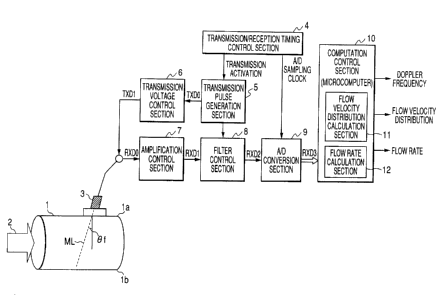
FIG. 1 is a diagram showing the schematic structure of
a Doppler ultrasonic flowmeter according to an exemplary
embodiment of the present invention.
FIG. 2 is a diagram for illustrating a quantization
error occurring in spatial resolution.
FIG. 3 is a diagram illustrating a method of correcting
a flow rate calculation equation according to the present
invention.
FIG. 4 is a diagram for illustrating a channel.
FIG. 5 is a diagram showing an exemplary experiment
result of an experiment.
FIG. 6 is a diagram illustrating a conventional flow
velocity distribution and flow rate computation.
Detailed Description
FIG. 1 is a diagram showing the schematic structure of
a Doppler ultrasonic flowmeter according to the present
invention.
The Doppler ultrasonic flowmeter shown in the
drawing includes an ultrasonic transducer 3, a
transmission/reception timing control section 4, a
transmission pulse generation section 5, a
9
CA 02497607 2005-02-18
transmission voltage control section 6, an amplification
control section 7, a filter control section 8, an A/D
conversion section 9, and a computation control section 10.
The computation control section 10 is exemplified by a
microcomputer (CPU/MPU), and includes a flow velocity
distribution calculation section 11, and a flow rate
calculation section 12.
Herein, the above-described components are
collectively referred to as an ultrasonic wave
transmission/reception section, i.e., the ultrasonic
transducer 3, the transmission/reception timing control
section 4, the transmission pulse generation section 5,
the transmission voltage control section 6, the
amplification control section 7, the filter control
section 8, and the A/D conversion section 9. As will
be described below, the ultrasonic wave
transmission/reception section forwards ultrasonic pulses
to a measurement fluid subject 2 in a tube 1 with an
arbitrary repetition frequency, and receives ultrasonic
echoes that are reflection waves derived by a
reflector or a tube inner wall. Thereby a Doppler shift
component is extracted for A/D conversion. Note here
that the Doppler ultrasonic flowmeter shown in the
drawing is the above-described clamp-on ultrasonic
CA 02497607 2005-02-18
flowmeter.
Note also here that the flow velocity distribution
calculation section 11 and the flow rate calculation
section 12 are implemented by the above-described
microcomputer (CPU or MPU; computer) executing a
predetermined program that is stored in an internal or
external storage device such as memory, which is not
shown in the drawing. Moreover, any data needed for such
program execution is also stored in the above-described
storage device.
The above-described ultrasonic pulse is repeatedly
transmitted with any predetermined pulse repetition
intervals. This pulse repetition interval is under the
control of the transmission/reception timing control
section 4. That is, the transmission/reception timing
control section 4 follows the pulse repetition interval
itself in order to instruct the transmission pulse
generation section 5 to generate a transmission pulse
every time a pulse transmission time occurs. The
transmission pulse generation section 5 has a quartz
oscillator that generates an electric signal TXDO of a
predetermined frequency of f0, and forwards the electric
signal TXDO (transmission pulse) to the transmission
voltage control section 6 responding to the
11
CA 02497607 2005-02-18
instruction. The transmission voltage control section 6
changes the voltage of the electric signal TXDO to a
predetermined voltage (transmission voltage), and forwards
the resulting electric signal TXD1 to the ultrasonic
transducer 3. In this manner, from the ultrasonic
transducer 3 into the tube 1, forwarded are the ultrasonic
pulses of an amplitude corresponding to the transmission
voltage.
The ultrasonic transducer 3 is a transmitter/receiver
for ultrasonic pulses, and the ultrasonic pulses provided
from the above-described ultrasonic transducer 3 are to
enter the fluid 2 flowing inside ~of the tube 1 with
an angle of 8f with respect to the normal to the tube
pipe axis in the upstream direction of the fluid 2.
These ultrasonic pulses are straight-line beams with
little divergence, the pulse width of which is of
about 5 mm, for example, and the pulses travel over a
measurement line ML shown in the drawing. Note that
in FIG. 1, a tube wall of the tube 1, to which the
ultrasonic transducer 3 is attached, is shown as a
tube wall la (entrance wall), and another tube wall
on the opposite side is shown as a tube wall lb
(opposite wall). Herein, the tube 1 has an internal
diameter of D.
12
CA 02497607 2005-02-18
After receiving ultrasonic echoes as a result of the
above-described ultrasonic pulses reflecting on a
reflector (e. g., air bubbles, foreign substances) included
in the fluid 2, the ultrasonic transducer 3 converts
those into electric signals, and forwards the resulting
echo waves RXDO to the amplification control section 7.
These echo waves RXDO are low in voltage level, and
by the amplification control section 7, those echo waves
RXDO are thus amplified with a predetermined
amplification ratio. After amplification the resulting
echo waves (i.e. amplification-controlled outputs RXD1)
are forwarded to the filter control section 8.
The filter control section 8 subjects the
amplification-controlled outputs RXD1 to separation into
transmission frequency components and Doppler shift
components. Thereafter , only the Doppler shift components
are extracted using a low-pass filter. Thus extracted
Doppler shift components are filter-controlled outputs
RXD2, and these are forwarded to the A/D conversion
section 9. The A/D conversion section 9 subjects the
filter-controlled outputs RXD2 to A/D conversion based
on a predetermined sampling clock, and passes the resulting
A/D-converted outputs RXD3 (digital data) to the
computation control section 10. Here, the sampling clock
13
CA 02497607 2005-02-18
for the A/D conversion section 9 to use at the time of A/D
conversion is the one generated and output by the
transmission/reception timing control section 4, and the
sampling clock is input.
Regardless of the fact that this is conventional
technology, the above-described filter control
section 8 is described here in detail for clarity. First
of all, with respect to the frequency of the transmission
pulses, the frequency of the reflection echoes shifts
in accordance with the flow velocity (i.e. speed of the
reflector) of the fluid (i.e. Doppler shift). Assuming
here that the transmission pulse have a frequency of
900 (kHz), and the reflection echoes have a frequency of
902 (kHz) , the frequency as a result of shifting as above
(hereinafter referred to as the Dopplerfrequency) will
be 2 (kHz). In the above-described filter control
section 8, signal components of the Doppler frequency
(i.e. Doppler shift components) are extracted. To be
specific, to extract the Doppler shift components, the
frequency of the transmitted ultrasonic pulses is
combined with the frequency of the received reflection
echoes, and then the transmission frequency componentsare
filtered. To be more specific, for such component
extraction, applied is a method of deriving analysis
14
" CA 02497607 2005-02-18
signals by orthogonal detection. In the method, with
respect to the reflection echo waves, multiplication is
performed to sine components and cosine components of the
transmission frequency so as to separate the reflection
echo waves into transmission frequency components and
Doppler shift components. Thereafter, a low-pass filter
is used to extract only the Doppler shift components.
Then, signals of thus extracted Doppler shift
components are converted into digital data in the A/D
conversion section 9 prior to input into the computation
processing section 10 exemplified by a microcomputer.
From the Doppler shift components~(cosine, sine), the
computation processing section 10 calculates the change
of phase angle in a predetermined period, and using the
result, the flow velocity distribution is derived. From
the flow velocity, the flow rate is derived by integration
computation.
Note that the transmission frequency is of the order
from hundreds of kHz to a few MHz, and the Doppler
frequency is of the order of a few kHz or less.
After the computation processing section 10
receives the output from the above-described A/D
conversion section 9, the flow velocity distribution
calculation section 11 first computes the flow velocity
,' CA 02497607 2005-02-18
of a measurement range along the above-described
measurement line ML, Moreover, based on the calculated
flow velocity distribution specifically for a
predetermined integration range, the flow rate computation
processing section 12 performs integration to calculate
the flow rate. In this example, although the flow
velocity distribution calculation section 11 is the same
as the conventional one, the flow rate computation
processing section 12 performs flow rate calculation
using a flow rate calculation equation in which a
quantization error occurring in a spatial resolution is
corrected.
Described below is the flow rate calculation
equation for use by the flow rate computation processing
section 12.
Here, first of all, the conventional flow rate
calculation equation in the flow rate computation
processing section 12 is described.
In this description, for example, the integration
method applies midpoint rule (midpoint rule; also
referred to as intermediate coordinate system), and the
integration range covers from the tube center (tube
axis) to the opposite wall Ib. The number of channels
found in such an integration range is assumed to be
16
CA 02497607 2005-02-18
N+1 including Channel 0 to channel N. As such, the
flow rate computation processing section 12 is
assumed to calculate the flow rate using Equation (1)
below, for example.
N N
Flow ratefa =tar v(r)-r~dr=2n v;-r;-dr,- 2~r-r,-dr; ~v;
- ~ ~ ~ . . . Equation ( 1 )
o mo ~.o 'w"~-~
Flow rate conversion factor
V;: Flow velocity of channel i
r;: Distance from center of tube to center of channel i
Dr: Width of channel i
In detail, the flow rate in a specific channel is
derived by calculating, for the respective channels, the
area of the tube cross section occupied by the
corresponding channel, and the thus calculated area is
multiplied by the flow velocity of the channel. Then,
the flow rates for each of the channels is added
together.
In this case, as shown in FIG. 2, as to the channels
locating at both ends in the integration range
(channel 0 and channel N), their areas may not be
entirely fit in the integration range. With this
being the case, using the above equation (1) to
calculate the flow rate will result in the inclusion
of the area that is not part of the integration
range. As a result, the calculation result will show
a higher flow rate than the actual flow rate. Such
17
CA 02497607 2005-02-18
an error is referred here to as quantization error
occurring in the spatial resolution (or integration
error resulted therefrom).
In this example, as to the channels locating at the
starting position and the end position of the
integration range (channel 0 and channel 1), the
above-described Equation (1) is corrected in such a
manner that any region occupied by the channel but not
being a part of the integration range is not
considered. For such correction, a description is
provided below referring to FIG. 3.
First of all, the channel 0 is described. In this
example, as shown in FIG. 3, the distance from the
center of the tube to the center of the channel 0 is ro.
In other words, in the area of the channel 0, the part
that is not part of the integration range (the shaded
area in the drawing) has a length of "Or/2-ro".
In the following description, the information
identifying which channel is channel 0, and the value of
ro in the above are derived.
First of all, as an input parameter, the distance DCx
from the entrance wall la to a capture starting
position is input. Here, the capture starting
position is a starting position for measurement of the
18
CA 02497607 2005-02-18
flow velocity distribution, and may be arbitrarily
determined by designers or others. As described in
the background art, the flow velocity is measured also
in the channels) that do not fit in the integration
range. Asshown in FIG.4,for example,a channel setting
can be made so that the center thereof comes at a
position having the distance D~H from the entrance
wall la, and the resulting channel is regarded as the
measurement starting channel for the flow velocity
distribution (i.e. CH(0) in the drawing). From CH(0),
channel setting continues at 0r intervals until the
opposite wall lb is reached. That is, CH(0) to CH(Z)
shown in FIG. 4 are set. Thereafter, through calculation
of the flow velocity on a channel basis, the flow
velocity distribution can be derived. However,
calculation of the flow rate is performed using the flow
velocity for each of the channels locating in the
integration range. In this example, as described in the
foregoing, the integration range covers the area having
the length of D/2 from the center of the tube to the
opposite wall. Accordingly, in FIG. 4 example, CH(M) is
the starting channel of the integration range, and this
corresponds to channel 0 in FIGS. 2 and 3. Note here
that the reason why M is replaced with 0 is to
19
CA 02497607 2005-02-18
permit application to the above Equation (1).
As such, through use of the above-described
distance D~H and Or, the distance CHD (X) from the
entrance wall la to the center of the respective
channels can be derived from the following Equation (2).
CHD (X) - D~ + Or x X . . . Equation ( 2 )
(X; 0 to Z )
The result of the calculation indicates that the
channel whose CHD(X) satisfies the following conditional
Equation (3) is the starting channel of the
above-described integration range (i.e. CH(M) of FIG. 4
and channel 0 of FIG. 3). Note here that the end
channel of the integration range can also be derived
from the conditional equation in which D/2 in the
following conditional equation is replaced with D.
D/2 - Or/2 <_ CHD(X) <_ D/2 + Or/2 ...Equation (3)
In FIG. 4, for example, CHD(M) satisfies the
conditional Equation (3), and thus the following
Equation (4) will lead to ro in the above.
ro = CHD(M) - D/2 ... Equation (4)
CA 02497607 2005-02-18
Further, ri in the above-described Equation (1)
can be derived from
ri = ro + Dr x i . . . Equat ion ( 5 )
Thereby, first of all, using ro in the above and the
distance rl from the center of the tube to the center
of the next channel 1 (rl - ro + 0r), the following
Equations (6) and (7), can be used to derive the width
Oro' and the central point ro' in the region of the
channel 0 that fit in the integral range (i.e. the
part not including the shaded area in the drawing).
Oro' - (ro + rl) /2 . . . Equation (6)
ro' - 0. 5 x (ro + rl) /2 . . . Equation (7)
Moreover, as to the channel N, presumably
herein, as shown in FIG. 3, the distance from the
center of the tube to the center of the channel N is
rN, and the distance from the center of the tube to
the center of the previous channel N-1 is rN_1 (these
values can be derived as described above). If this is
the case, in the area of the channel N, the area
fitting in the integration range (i.e. the area not
including the shaded area in the drawing), the width
21
CA 02497607 2005-02-18
OrN, and the central pointrN,thereof can be derived as
follows.
~N ~ _ D _ r,~_, +rN ~ rN,= _1 D + rH_, + r~,
2 2 2~(2 2
... Equation (9)
If the above-described Equation (1) is corrected
based on the result derived as above, the resulting
flow rate calculation equation after correction will be
the following Equation (8).
H-I
Flow rate Q Q=2~Cvo'ro~'d'o~+~v:'r'd;+v"~rN'~dr"'
~.I J
o.~l.~~.~ro+r,~ "'' ".CI.rD r"_,+r"~~'~D r"I +r"~
=2~t v l2 2 J 2 +~ (r .d;) 'v~ +v z l Z + 2 2 2 - ... Equation ($)
Flow rate coefficient of how rate conversion factor ~~oW' rate coefficient of
end
starting channel channel
That is, for the channels at a starting
position and at an end position, applied thereto is
such a calculation equation that the area occupied by
the channels but not being part of the integration
range is not taken into consideration.
The flow rate computation processing section 12
calculates the flow rate using Equation (8). Accordingly,
with no influence by quantization errors occurring in
the spatial resolution, the flow rate measurement can be
performed with a high precision.
22
CA 02497607 2005-02-18
FIG. 5 shows an exemplary experimental result
derived through an experiment.
With this experiment, a tube having the internal
diameter D of 50 (mm) is used, the fluid flowing inside
of the tube is water, and the division number (the
number of channels) is 40. For the fluid flowing with
average flow velocities of 5 (m/s) and of 3(m/s), the
flow rate computation processing section 12 measures
the flow rate using the corresponding flow rate
calculation equation, i.e., corrected or not corrected.
Moreover, an electromagnetic flowmeter is used as a
reference meter.
As a result, as shown in the drawing, in a case where
the average flow velocity is 5 (m/s), the flow rate
measurement result using the electromagnetic flowmeter
is 647.17 (L/min), and the result using the
not-corrected equation is 723.54 (L/min). The error is
11.80 (%). On the other hand, the result using the
corrected equation is 649.11 (L/min) with little error
(about 0.3 %). The result is almost the same for the
case with the average flow velocity of 3 (m/s).
Therefore, when the flow rate calculation
Equation (8) having been corrected as described above
is used, the flow rate measurement can be performed
23
CA 02497607 2005-02-18
with a very high precision. Note that, in spite of the
advantage of achieving flow rate measurement with a
high precision, the electromagnetic flowmeter has a
drawback of requiring time and effort for installation
at very high cost compared with the clamp-on type flowmeter.
Note that described above is the case of applying
the midpoint rule as the integration method. This
example is not meant to be limiting; this method is
applicable with other integration methods (e. g.
trapezoidal rule, Simpson's rule).
Description of Reference Numerals
1 tube
2 fluid
3 ultrasonic transducer
4 transmission/reception timing control section
5 transmission pulse generation section
6 transmission voltage control section
7 amplification control section
8 filter control section
9 A/D conversion section
10 computation control section
11 flow velocity distribution calculation section
12 flow rate calculation section
24