Note: Descriptions are shown in the official language in which they were submitted.
CA 02497670 1994-10-31
DEVIANDES OU BREVETS VOEU1~IINEIJX
LA PRESENTE PARTIE DE CETTE DEIYLaNDE OU CE BREVETS
COyIPREND PLUS D'LrN T0lViE.
CECI EST LE TOIYIE ~ DE
NOTE: Puur les tomes additionels, veillez contacter 1e Bureau Canadien des
Brevets.
JiJMBO APPLICATIONS / PATENTS
TI'!IS SECTION OF THE APPLICATION l PATENT CONTAINS lViORE
THAN ONE VOLUME.
THIS IS VOLUME ~ OF
NOTE: For additional volumes please contact the Canadian Patent Office.
CA 02497670 1994-10-31
A Method For Commnunicating In A Wireless
Comanunication System
This is a divisional application of Canadian Patent
Application Serial No. 2,303,751, which in turn is a
division of Canadian Patent Application No. 2,134,695 filed
October 31, 1994.
This application contains subject matter which is
related to U.S. Patent 5,353,332 entitled "Method and
Apparatus for Communication Control in a Radiotelephone
System" issued October 4, 1994; U.S. Patent 5,404,355
entitled "Digital Control Channel" issued April 4, 1995 and
U.S. Patent 5,610,917 entitled "Layer 2 Protocol for the
Random Access Channel and the Access Response Channel"
issued March 11, 1997. It should be understood that the
expression "the invention" and the like encompasses the
subject matter of both the parent and the divisional
applications.
1
CA 02497670 1994-10-31
Patent Application
Docket #15735/0073
E813 3
BACKGROUND OF THE INVENTION
Field of the invention
The present invention relates to wireless
communication systems, and more particularly, to a method
and apparatus for communicating information in wireless
communications systems including, far example, a cellular
radio system.
history of the Prior Art
Cellular Telephone Service
Cellular mobile telephony is one of the fastest
growing segments in the worldwide telecommunications
market. Between 1984 and 1992, for example, the number
of mobile telephone subscribers in the United States grew
from around 25,000 to over 10 million. It is estimated
that the number of subscribers will rise to nearly 22
million by year end 1995 and to 90 million by the year
2000.
Cellular telephone service operates much like the
fixed, wireline telephone service in homes and offices,
except that radio frequencies rather than telephone wires
are used to connect telephone calls to and from the
mobile subscribers. Each mobile subscriber is assigned
a private (10 digit) directory telephone number and is
billed based on the amount of "airtime" he or she spends
talking on the cellular telephone each month. Many of
the service features available to landline telephone
users, e.g., call waiting, call forwarding, three-way
calling, etc., are also generally available to mobile
subscribers.
2
CA 02497670 1994-10-31
Patent Application
Docket #15735/0073
E8133
In the United States, cellular licenses are awarded
by the Federal Communications Commission (FCC) pursuant
to a licensing scheme which divides the country into
geographic service markets defined according to the 1980
Census. Only two cellular licenses are awarded for each
market. The two cellular systems in each market are
commonly referred to as the "A" system and "B" system,
respectively. Each of the two systems is allocated a
different frequency block in the 800 MHz band (called the
A-band and B-band, respectively). To date, the FCC has
released a total of 50 Mhz for cellular services (25 MHz
per system).
Mobile subscribers have the freedom to subscribe to
service from either the A-system or the H-system operator
(or both). The local system from which service is
subscribed is called the "home" system. When travelling
("roaming"j outside the home system, a mobile subscriber
may be able to obtain service in a distant system if
there is a roaming agreement between the operators of the
home and "visited" systems.
The Cellular System
In a typical cellular radio system, a geographical
area, e.g., a metropolitan area, is divided into several
smaller, contiguous radio coverage areas called "cells."
The cells are served by a series of fixed radio stations
called "base stations." The base stations are connected
to and controlled by a mobile services switching center
(MSC). The MSC, in turn, connected to the landline
(wireline) public switched telephone network (PSTN). The
3
CA 02497670 1994-10-31
Patent Application
Docket #15735/0073
E8133
telephone users (mobile subscribers) in the cellular
radio system are provided with portable (hand-held),
transportable (hand-carried) or mobile (car-mounted)
telephone units (mobile stations) which communicate voice
and/or data with the MSC through a nearby base station.
The MSC switches calls between and among wireline and
mobile subscribers, controls signalling to the mobile
stations, compiles billing statistics, and provide$ for
the operation, maintenance and testing of the system.
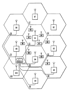
FIG. 1 illustrates the architecture of a
conventional cellular radio system built according to the
Advanced Mobile Phone Service (AMPS) standard. In FIG.
1, an arbitrary geographic area may be seen divided into
a plurality of contiguous radio coverage areas, or cells,
C1-C10. While the system of FIG. 1 is, for illustration
purposes, shown to include only ten cells, the number of
cells may be much larger in practice. Associated with
and located in each of the cells C1-C10 is a base station
designated as a corresponding one of a plurality of base
stations B1-B10. Each of the base stations 81-B10
includes a plurality of channel units, each comprising a
transmitter, a receiver and a controller, as is well
known in the art.
In FIG. 1, the base stations H1-B10 are located at
the center of the cells C1-C10, respectively, and are
equipped with omni-directional antennas transmitting '
equally in all directions. In this case, all the channel
units in each of the base stations B1-B10 are connected .
to one antenna. However, in other configurations of the
4 -
CA 02497670 1994-10-31
Patent Application
Docket #15735/0073
E8133
cellular radio system, the base stations H1-H10 may be
located near the periphery, or otherwise away from the
centers of the cells C1-C10 and may illuminate the cells
C1-C10 with radio signals directionally. For example,
the base station may be equipped with three directional
antennas, each one covering a 120 degrees sector cell as
shown in FIG. 2. In this case, some channel units will
be connected to one antenna covering one sector cell,
other channel units will be connected to another antenna
covering another sector cell, and the remaining channel
units will be connected to the remaining antenna covering
the remaining sector cell. In FIG. 2, therefore, the
base station serves three sector cells. However, it is
not always necessary for three sector cells to exist and
~15 only one sector cell needs to be used to cover, for
example, a road or a highway.
Returning to FIG. 1, each of the base stations B1-
B10 is connected by voice and data links to a mobile
switching center (MSCj 20 which is, in turn, connected to
a central office (not shown] in the public switching
telephone network (PSTNj, or a similar facility, e.g., an
integrated system digital network (ISONj. The relevant
connections and transmission modes between the mobile
switching center MSC 20 and the base stations H1-B10, or
between the mobile switching center MSC 20 and the PSTN
or ISDN, are well known to those of ordinary skill in the
art and may include twisted wire pairs, coaxial cables,
fiber optic cables or miczowave radio channels operating
in either analog or digital mode. Further, the voice and
5
CA 02497670 1994-10-31
Patent Application
Docket (15735/0073
E8133
data links may either be provided by the operator or
leased from a telephone company (telco).
With continuing reference to FIG. 1, a plurality of
mobile stations M1-M10 may be found within the cells C1
C10. Again, while only ten mobile stations are shown in
FIG. 1, the actual number of mobile stations may be much
larger in practice and will generally exceed the number
of base stations. Moreover, while none of the mobile
stations M1-M10 may be found in some of the cells C1-C10,
the presence or absence of the mobile stations M1-M10 in
any particular one of the cells C1-C1o depends on the
individual desires of each of the mobile subscribers who
may travel from one location in a cell to another or from
one cell to an adjacent or neighboring cell.
Each of the mobile stations M1-M10 includes a
transmitter, a receiver, a controller and a user
interface, e.g., a telephone handset, as is well known in
the art. Each of the mobile stations M1-M10 is assigned
a mobile identification number (MIN) which, in the United
States, is a digital representation of the telephone
directory number of the mobile subscriber. The MIN
defines the subscription of the mobile subscriber on the
radio path and is sent from the mobile station to the MSC
20 at call origination and from the MSC 20 to the mobile
station at call termination. Each of the mobile stations
M1-M10 is also identified by an electronic serial number
(ESN) which is a factory-set, "unchangeable" number
designed to protect against the unauthorized use of the
mobile station. At call origination, for example, the
6
CA 02497670 1994-10-31
Patent Application
Docket #15735/00?3
E8133
mobile station will send .the ESN to the MSC 20. The MSC
20 will compare the received ESN to a "blacklist" of the
ESNs of mobile stations which have been reported to be
stolen. If a match is found, the stolen mobile station
~ will be denied access.
Each of the cells C1-C10 is allocated a subset of
the radio frequency (RF) channels assigned to the entire
cellular system by the concerned government authority,
e.g., the Federal Communications Commission (FCC) in the
United States. Each subset of RF channels is divided
into several voice or speech channels which are used to
carry voice conversations, and at least one paging/access
or control channel which is used to carry supervisory
data messages, between each of the base stations B1-B10
and the mobile stations M1-M10 in its coverage area.
Each RF channel comprises a duplex channel (bidirectional
radio transmission path) between the base station and the
mobile station. The RF channel consists of a pair of
separate frequencies, one for transmission by the base
station (reception by the mobile station) and one for
transmission by the mobile station (reception by the base
station). Each channel unit in the base stations B1-H10
normally operates on a preselected one of the radio
channels allocated to the corresponding cell, i.e., the
transmitter (TX) and receiver (RX) of the channel unit
are tuned to a pair of transmit and receive frequencies,
respectively, which is not changed. The transceiver
(TX/RX) of each mobile station M1-M10, however, may tune
to any of the radio channels specified in the system.
7
CA 02497670 1994-10-31
Patent Application
Docket #15735/0073
E8133
Depending on capacity needs, one cell may have 15
voice channels, while another may have over a 100 voice
channels, and corresponding channel units. Generally
speaking, however, there is only one control channel (CC)
in each omnidirectional or sector cell served by a base
station, i.e., a base station serving an omnidirectional
cell (FIG. 1) will have one control channel unit while a
base station serving three sectors cells (FIG. 2) will
have three control channel units. The RF (control and
voice) channels allocated to any given cell may be
reallocated to a distant cell in accordance with a
frequency reuse pattern as is well known in the art. To
avoid radio interference, all radio channels in the same
cell will operate on different frequencies and,
I5 furthermore, the radio channels in any one cell will
operate on a set of frequencies which is different from
that used in any neighboring cell.
When in the idle state (turned on but not in use),
each of the mobile stations M1-M10 tunes to and then
continuously monitors the strongest control channel
(generally, the control channel of the cell in which the
mobile station is located at that moment) and may receive
or initiate a telephone call through the corresponding
one of the base stations B1-B10 which is connected to the
mobile switching center MSC 20. When moving between
cells while in the idle state, the mobile station will
eventually "lose" radio connection on the control channel
of the "old" cell and tune to the control channel of the
"new" cell. The initial tuning to, and the change ot,
8
CA 02497670 1994-10-31
Patent Application
Docket (15735/0073
E8133
control channel are both accomplished automatically by
scanning all the control channels in operation in the
cellular system to find the "best" control channel (in
the United States, there are 21 "dedicated" control
channels in each AMPS system, i.e., their TX/RX
frequencies are predefined and cannot be changed, which
means that the mobile station has to scan a maximum
number of 21 channels). When a control channel with good
reception quality is found, the mobile station remains
tuned to this channel until the quality deteriorates
again. In this manner, all mobile stations are always
"in touch" with the system.
While in the idle (standby) state, each of the
mobile stations M1-M10 continuously deteraines whether a
page message addressed to it has been received over the
control channel. When, for example, an ordinary
(landline) subscriber calls one of the mobile
subscribers, the call is directed from the PSTN to the
MSC 20 where the dialed number is analyzed. If the
dialed number is validated, the MSC 20 requests some or
all of the base stations B1-B10 to page the called mobile
_ station throughout their corresponding cells Ci-C10.
Each of the base stations 81-B10 which receive the
request from the MSC 20 will then transmit over the
control channel of the corresponding cell a page message
containing the MIN of the called mobile station. Each of
the idle mobile stations M1-M10 will compare the MIN in
the page message received over the control channel being
monitored With the MIN stored in the mobile station. The
9
CA 02497670 1994-10-31
Patent Application
Docket #15735/0073
E8133
called mobile station with the matching MIN will
automatically transmit a page response over the control
channel to the base station which forwards the page
response to the MSC 20.
Upon receiving the page response, the MSC 20 selects
an available voice channel in the cell from which the
page response was received, turns the selected voice
channel transceiver on, and requests the base station in
that cell to order the mobile station via the control
channel to tune to the selected voice channel (the MSC
keeps a list of all of the channels in its service area
and their status, i.e., free, busy, blocked, etc., at any
time). A through-connection is established once the
mobile station has tuned to the selected voice channel.
When, on the other hand, a mobile subscriber
initiates a call, e.g., by dialing the telephone number
of an ordinary subscriber and pressing the "send" button
an the telephone handset in the mobile station, the MIN
and ESN of the mobile station and the dialed number are
sent over the control channel to the base station and
forwarded to the MSC 20 which validates the mobile
station, assigns a voice channel and establishes a
through-connection for the conversation as before.
If the mobile station moves between cells while in
the conversation state, the MSC will perform a "handoff"
of the call from the old base station to the new base
station. The MSC selects an available voice channel in
the new cell and then orders the old base station to send
to the mobile station on the current voice channel in the
CA 02497670 1994-10-31
Patent Application
Docket X15735/00?3
~8133
old cell a handoff message which informs the mobile
station to tune to the selected voice channel in the new
cell. The handoft message is sent in a "blank and burst"
mode which causes a short but hardly noticeable break in
9 the conversation. Upon receipt of the handoff message,
the mobile station tunes to the new voice channel and a
through-connection is established by the MSC via the new
cell. The old voice channel in the old cell is marked
idle in the MSC and may be used for another conversation.
In addition to call originations and page responses,
an AMPS mobile station may access the cellular system for
registrations. Two types of registrations are possible
in AMPS: (i) periodic registration which is based on time
or, more specifically, on the REGID value ("current
time") and REGINCR value ("registration period")
transmitted by the base station and the NXTREG value
("wake-up time") stored in the mobile station, and (ii)
system area registration which is based on location or,
more specifically, on the system identification (SID)
transmitted in the serving cellular system. Periodic
registration may be used to determine whether a mobile
station is active (within radio range and switched on) or
not in a cellular system. System area registration may
be used to determine when a mobile station has crossed
the border. from one cellular system to another.
Upon receipt of a R~GID message on the forward
control channel (base station to mobile station), if
registration is enabled in the serving cellular system,
the mobile station compares the R~GID value to the NXTR~G
11
- CA 02497670 1994-10-31
Patent Application
Docket (15735/0073
E8133
value and compares the last received SID value with the
value of the SID of the cellular system in which the
mobile station last registered. If either the value of
REGID is greater or equal to the value of NXTREG
indicating that periodic registration is due, or the
value of the last received SID is different than the
value of the last stored SID indicating that the mobile
station has travelled from one cellular system to another
since the last successful registration, the mobile
station will automatically send a registration access
message over the reverse control channel (mobile station
to base station) and will update the NXTREG value with
the sum of the last received REGID value and REGINCR
value, after receipt of a registration acknowledgement
message on the forward control channel (the mobile
station also updates the NXTREG value after each call
origination or page response).
Radio Transmission Format
From its inception, the radio transmission format in
cellular systems has been analog frequency modulation
(FM). In each cell, the voice (analog) signals and data
(digital) signals form the input signals to a transmitter
(in the base station or the mobile station) which
generates a sinusoidal carrier wave having a constant
frequency corresponding to one of the frequencies
allocated to the cell. With FM, the frequency of the
carrier wave is modulated (varied) in proportion to the
instantaneous amplitude of the input signal. The
modulated carrier occupies a relatively narrow region of
12
CA 02497670 1994-10-31
Patent Application
Docket X15735/0073
E8133
the spectrum about a nominal center frequency (the
unmodulated carrier frequency). The resulting deviation
of the modulated carrier wave frequency about the
unmodulated (center) frequency is normally limited (by
the use of bandpass filters) within a certain bandwidth,
e.g., 30 IUiz in the U.S., to avoid overlapping adjacent
RF channels and causing adjacent channel interference.
Each analog voice signal, therefore, occupies 30 IUiz of
spectrum, and a voice conversation requires 60 I~iz.
In the conventional AMPS system, therefore, an
analog speech signal modulates the carrier wave used for
transmission over the RF channel. The AMPS system uses
analog frequency modulation (FM) and is a single-channel-
per-carrier (sCPC) system, i.e., one voice circuit
(telephone conversation) per RF channel. The radio
channel access scheme in the AMPS system is frequency
division multiple access (FDMA) in which multiple users
have access to the same set of RF channels, each user is
assigned one of the available RF channels on demand, and
different users are assigned different RF channels.
The Migration from Analoq_,to Digital
Recent developments have ushered in a new digital
era for cellular communications. The main driving force
behind the switch to digital has been the desire to
increase spectrum efficiency to meet the ever-increasing
demands on system capacity. As each cellular system is
allocated a finite amount of radio spectrum, capacity may
be increased by reducing the amount of bandwidth required
for each voice channel or, conversely, by sharing each RF
13
CA 02497670 1994-10-31
Patent Application
Docket X15735/0073
E8133
channel among several voice conversations. This is made
possible with the use of digital technology.
By encoding (digitizing and compressing) speech from
several voice circuits prior to modulation and
transmission, a single RF voice channel may be shared by
several digital speech channels instead of being occupied
by only one analog speech channel (one voice
conversationj. In this manner, the channel capacity and,
consequently, the overall system capacity, may be
increased dramatically without increasing the bandwidth
of the voice channel. As a corollary, the cellular radio
system is able to serve a substantially greater number of
mobile stations at a significantly lower cost, e.g., a
smaller number of channel units (transceivers) required
in the base stations. Furthermore, the digital format
facilitates integration of the cellular system with the
emerging digital network.
In the United States, the migration from analog to
digital has been spearheaded by the Electronics
Industries Association (EIAj and the Telecommunication
Industry Association (TIAj. The EIA/TIA have undertaken
the task of fonaulating a common air interface standard
to meet industry requirements for the next generation
digital cellular systems. To date, the EIA/TIA has
published two separate air interface standards which are
based on different radio channel multiple access schemes.
The first EIA/TIA interim standard (ISj is based on a
time division multiple access (TDMAj scheme and is known
as the "Dual-Mode Mobile Station-Base Station
14
CA 02497670 1994-10-31
Patent Application
Docket #15735/0073
E8133
Compatibility Standard" (IS-54B). The second standard is
based on a code division multiple access scheme (CDMA)
and is known as "Mobile Station-Base Station
Compatibility Standard for Dual-Mode Wideband Spread
Spectrum Cellular System" (PN-3118 to be published as IS-
95). Copies of these standards and the various revisions
thereof may be obtained from the Electronics Industry
Association;
2001 Pennsylvania Avenue, N.W., Washington; D.C. 20006.
The term "dual-mode" in these two standards refers
to the capability of the system to operate in either an
analog or a digital mode. The analog mode of operation
uses analog FM and draws on the older EIA/TIA-553
standard which is based on the AMPS standard. The
digital mode of operation uses TDMA (IS-54B) or CDMA (PN-
3118). The dual-mode capability facilitates the
deployment of digital systems through a gradual reduction
in analog capacity, i.e., the removal of RF channels from
analog FM service to provide digital service. This was
deemed desirable to ease the transition from analog to
digital and to provide so-called "backward" compatibility
with the existing analog system. Although the analog and
digital modes of operation can exist alone, the goal is
for them to coexist, at least in the short term, in order
to allow roaming in existing systems which have not
deployed the new digital technology. In the transition
phase, existing analog-only mobile stations will continue
CA 02497670 1994-10-31
Patent Application
Docket ~15T35/0073
E8133
to be served while the use of digital-capable mobile
stations and base stations becomes more widespread.
A mobile station which complies with the defined
specifications (IS-54B or PN-3118) can obtain service
from an analog-only base station, a digital-only base
station or an analog-digital (dual-mode) base station.
The type of system serving the mobile station will depend
on the availability of digital service (TDMA or CDMA) in
the geographic area of the mobile station and the
preference of the mobile subscriber. At call set-up or
handoff, a dual-mode mobile stations can access either an
analog voice channel (AVCj or, alternatively, a digital
traffic channel (DTC). An analog-only or a digital-only
mobile station, however, can only be assigned an AVC or
DTC, respectively.
DMA Systems
TDMA is a multiple access scheme which is based on
time division multiplexing (TDM) techniques long used in
the land-line telephone network to carry multiple
telephone conversations simultaneously over one physical
channel. In the wire-line telephone network, analog
speech signals transmitted by local telephone subscribers
over separate lines (subscriber loops) to the local
telephone company (telco) central office are sequentially
sampled and the amplitudes of the samples are quantized
and then encoded into binary numbers represented by
constant amplitude pulses in a process called pulse code
modulation (PCM). A predetermined number of PCM channels
(digital speech channels) are transmitted in a series of
16
CA 02497670 1994-10-31
Patent Application
Docket #15735/0073
E8I33
frames, each containing a burst of information (coded
samples) from each of the PCM channels. The bursts from
the different PCM channels occupy different time slots
(time intervals) in each frame transmitted on the
physical channel, e.g., copper wire plant. Most long-
distance telephone calls are transmitted through the
switching hierarchy using TDM. This technique can also
be applied to transmissions on the RF channels of a
cellular radio system.
An RF channel operating in TDM mode is divided into
a series of repeating time slots (periodic train of time
intervals) each containing a burst of information from a
different data source, e.g., encoded speech from a source
coder for a voice circuit. The time slots are grouped
into frames of a predetermined duration. The number of
time slots per frame varies depending on the number
digital channels sought to be accommodated on the RF
channel given the coding rates of the digital channels,
the modulation level and the bandwidth of the RF channel.
Each slot in a frame normally represents a different
digital channel. The length of each TDM frame on the RF
channel, therefore, is the minimum amount of time between
two repeating time slots which are used by the same
digital channel (assigned to the same user). In other
words, each TDM frame consists of no more than one slot
for each user.
According to IS-54B, each digital TDM RF channel can
carry from three to six digital speech channels (three to
six telephone conversations) depending on the source rate
17
CA 02497670 1994-10-31
Patent Application
Docket #15735/0073
E8133
of the speech coder used for each digital speech channel
(the modulation level and channel bandwidth are set in IS-
54B). The speech coder for each digital traffic channel
(DTC) can operate at either full-rate or half-rate (full-
rate speech coders are expected to be used in the near
future until half-rate coders are developed which produce
acceptable speech quality). A full-rate DTC requires twice
as many time slots in a given time period as a half-rate
DTC. In IS-548, each TDM RF channel can carry up to three
full-rate DTCs or six half-rate DTCs.
The TDM RF channel frame structure for IS-54B is shown in
FIG. 3. The TDM channel occupies one of the 30 KHz channels
of the existing analog system. Each "frame" on the TDM RF
channel comprises six equally sized time slots (1-6) and the
length of the frame is 40 ms (25 frames per second). Each
full-rate DTC uses two equally spaced slots of the frame
shown in FIG. 3, i.e., slots 1 & 4, or slots 2 & 5, or slots
3 & 6. When operating at full-rate. the TDM RF channel may
be assigned to three users (A-C), i.e., user A is assigned
to slots 1 & 4; user B is assigned to slots 2 & 5; and user
C is assigned to slots 3 & 6 of the "frame" shown in FIG. 3
(for full-rate, therefore, each TDM frame actually consists
of three slots and not six slots, and is 20 ms long and not
40 ms long). Each half-rate DTC uses one time slot of the
frame shown in FIG. 3. At half-rate, the TDM RF channel may
be assigned to six users (A-F) with each of the users A-F
being assigned to one of the six slots of
18
CA 02497670 1994-10-31
Patent Application
Docket #15735/0073
E8133
the frame shown in FIG. 3 (for half-rate, each TDM frame
actually consists of six slots and coincides with the
definition of "frame" in IS-548).
Hence, unlike an analog FDMA cellular system in
which the base station and the mobile station transmit
and receive continuously over an RF channel, a TDMA
cellular system operates in a.buffer and burst dis
continuous transmission mode. Each mobile station
transmits (and receives) in an assigned slot on the RF
channel. At full rate, for example, the mobile station
of user A would transmit on slot 1, hold for slot 2,
receive in slot 3, transmit in slot 4, hold for slot 5,
and receive in slot 6, and then repeat the cycle (the
transmit and receive slots are offset from each other to
I5 avoid using duplexer circuitry which would otherwise be
needed to allow the transmitter and receiver at the
mobile station to operate simultaneously). The mobile
station, therefore, transmits (or receives) in a fraction
of the time (one third for full rate and one sixth for
half-rate) and can be switched off to save power the rest
of the time.
CDMA Systems
CDMA is a multiple access scheme which is based on
spread spectrum communication techniques long used in
military communications to counteract radio jamming and
to protect against interception. Unlike FDMA and TDMA
systems in which each transmission (signal) , at any given
time, is confined to its own separate frequency and its
own distinct channel isolated from adjacent channels,
19
CA 02497670 1994-10-31
Patent Application
Docket #15735/0073
E8133
CDMA systems transmit multiple signals simultaneously
over the same spectrum band. The two chief spread
spectrum techniques are frequency-hopping spread spectrum
and direct-sequence or noise-modulated spread spectrum.
In frequency-hopping spread spectrum, a relatively
wide band of frequencies (e.g. , several MIiz) is divided
into a large number of much narrower channels. -The
transmitter "hops" from one channel to another, i.e.,
transmits a very short burst in one channel after
another. The hopping sequence is pseudo-random,
generated according to a key which is available to both
transmitter and receiver. The total transmission, viewed
over a longer period than the individual bursts, appears
to occupy the entire bandwidth thus "spreading" the
spectrum, although at any moment, for any one burst, it
occupies only a small percentage of the channel. Many
users can share the same channel with each user's
transmissions following an orthogonal pseudorandom
sequence of frequency hops.
The PN-3118 standard uses direct sequence or direct
coding spread spectrum which is a digital version of
-~ noise modulation. In noise modulation, the original
signal is added to (mixed with) a stronger noiselike
signal with known characteristics. The resulting signal
modulates a carrier for transmission to a receiver. At
the receiver, a copy of the noiselike input to the
transmitter is subtracted from the received signal to
recover the original signal. In direct sequence, a fast
rate pseudorandom binary sequence is used for the
CA 02497670 1994-10-31
Patent Application
Docket #15735/0073
E8133
noiselike signal. This pseudonoise (PN) sequence is
added to the digital information signal (e. g., digital
speech) and the resulting bit stream is transmitted. At
the receiver, the PN sequence is subtracted to yield the
information signal. Because the transmitted signal has
a high bit rate (e. g., 100 Mbps), a "spread spectrum"
(i.e., wide band) is required (e. g., 100 MHz), as with
frequency hopping spread spectrum. Unlike frequency-
hopping spread spectrum, however, direct sequence spread
spectrum transmissions occupy the entire' channel
bandwidth all of the time. Here also, many users can
share the same channel with each user being assigned a
code for generating the orthogonal random sequence which
is mixed with the information signal. The signals are
separated in each receiver by using a correlator or a
matched filter which accepts only signal energy from the
assigned binary sequence for despreading.
FIG. 4 shows the overall structure of the forward
(base station to mobile station) CDMA channel specified
in PN-3118. The forward CDMA channel occupies a 1.23 MFiz
segment of spectrum centered on one of the 30 FUiz
channels of the existing analog system. According to PN-
3118, the forward CDMA channel consists of up to 64 code
channels (WO-W63) assigned to different uses, far
example, a pilot channel (WO), a synchronization channel
(W32), seven paging channels (W1-W7), and fifty five
traffic channels (W8-W31 and W33-W63). Each of these
code channels is spread by an orthogonal PN sequence at
a fixed chip rate of 1.23 Mcps (a "PN chip" is one bit in
21
CA 02497670 1994-10-31
Patent Application
Oocket (15735/0073
E8133
the PN sequence),. Multiple for-.rard CDMA channels may be
transmitted by a base station in a frequency division
multiplexed manner.
The pilot channel carries an unmodulated direct
sequence spread spectrum signal which is continuously
transmitted on each active forward CDMA channel of a base
station. A mobile station operating within the coverage
area of the base station uses this signal for
synchronization (acquisition, timing and phase reference
for coherent demodulation) and for signal strength
comparisons between base stations to determine when to
handoff . Each base station uses a time offset of the
pilot PN sequence to identify the forward CDMA channels.
Different base stations are, therefore, identified by
different pilot PN sequence offsets.
The sync channel is used by the mobile station to
obtain system configuration and timing information (e.g.,
system identification, system time, pilot PN sequence
offset, paging channel data rate, etc.). Each traffic
channel (user) is identified by a distinct long code
sequence (1.23 Mcps) which is added to the information
bits prior to spreading by the PN sequence. Each paging _
channel is divided into a number of 80 ms time slots. A
mobile station can operate in either "slotted" or "non-
slotted" mode for purposes of receiving paging and
control messages on the paging channel. In the slotted
mode, the mobile station monitors the paging channel only
during certain assigned slots. In the non-slotted mode,
22
CA 02497670 1994-10-31
Patent Application
Docket X15735/0073
E813 3
the mobile station monitors all slots of the paging
channel.
~iybrid Systems
Some systems use a combination of access methods.
The IS-54B digital cellular standard, for example, uses
a combination of FDMA and TDMA. More specifically, IS
54B uses 30 Khz FDMA channels which are subdivided into
3 or 6 time slots for TDMA transmissions (3 or 6 voice
calls per 30 Khz of bandwidth). Similarly, the CDMA
system can also be a hybrid of FDMA and CDMA techniques
where the total system bandwidth is divided into a set of
wideband channels, each of which contains a large number
of CDMA signals.
Personal Communications Services fPCS1
Cellular telephony had its origin in the provision
of car telephone service. More recently, however, there
has been an increasing shift towards the use of
lightweight pocket telephones in homes, offices, public
meeting places, and in virtually any other place the user
can obtain service. The next step in this evolution is
the emerging concept of "personal communication services"
(PCS) , or what has sometimes been referred to as services
at "walking speeds." The idea is that not only telephone
calls but also facsimile, computer data, paging messages
and even video signals can be transmitted and received by
a user moving around, for example, inside a building, a
factory, a warehouse, a shopping mall, a convention
center, an airport, or an open area.
23
CA 02497670 1994-10-31
Patent Application
Docket #15735/0073
E8133
PCS systems operate on lower power, and use smaller
cellular structures than conventional wide area
(vehicular) cellular systems, to provide the high-
quality, high-capacity radio coverage needed for business
and other applications. By reducing the transmit power
of the base station, the size of the cell (or cell
radius) and, with it, the frequency reuse distance are
reduced resulting in more channels per geographic area.
Additional benefits of a smaller cell include a longer
talk-time (battery life time) for the user since the
mobile station will use substantially lower transmit
power than in a larger cell.
The industry has grown accustomed to using the terms
"macrocell," "micocell," and "picocell" to distinguish
the relative size of the cells required for a particular
application (indoor or outdoor). The term "macrocell"
generally refers to a cell which is comparable in size to
cells in a conventional cellular telephone system (e. g.,
a radius of 1 Km or more). A macrocell serves rapidly
moving users and covers low to medium usage areas. The
terms "microcell" and "picocell," on the other hand,
refer to the progressively smaller cells which are used
in a PCS system, for example. A microcell serves the
slowly moving users and may cover a public indoor or
outdoor area, e.g., a convention center or a busy street.
A picocell may cover an office corridor or a floor of a
high rise building. Microcells and picocells can also
cover high-density pedestrian areas or busy thorough-
24
CA 02497670 1994-10-31
Patent Application
Docket #15735/0073
E8133
fares (streets or highways) in a conventional cellular
system.
It is now clear that future cellular systems will
likely implement a hierarchial cell structure of
macrocells, microcells and picocells. From a system
(MSC) perspective, the base stations in the microcells
and picocells can be viewed as extensions of the base
stations in adjoining or overlapping macrocells. In this
case, the microcell and picocell base stations may be
connected to the macrocell base station via digital
transmission lines, for example. Alternatively, the
microcells and picocells may be treated just like
macrocells and be connected directly to the MSC.
From a radio coverage perspective, the macrocells,
microcells and picocells may be distinct from each other
or, alternatively, overlaid one on top of the other to
handle different traffic patterns or radio environments.
For example, handoff between microcells may sometimes be
difficult to perfona around street corners, particularly
where the users are moving so rapidly that the signal
strength variations are in excess of 20 d8 per second.
In this situation, it may be possible to use an
"umbrella" macrocell for the rapidly moving users and to
use microcells for the slowly moving users. By managing
different types of users differently in this way, handoff
between microcells may be avoided for the rapidly moving
users Which are subject to the severe street corner
ef f ects .
CA 02497670 1994-10-31
Patent Application
Docket #15735/0073
E8133
It will be readily appreciated that the capacity
improvements sought for the next generation cellular
systems can be achieved by more advanced macrocellular
technology, e.g., digital TDMA or CDMA, or by the
introduction of microcells and picocells to the specific
areas where increased capacity is needed, or by a
combination of both approaches. Thus, for example,
analog microcells may be implemented to cover "dead
spots" (areas where topography, zoning or other
restrictions prevent penetration of radio signals) or
"hot spots" (areas with heavy localized traffic). In
this instance, coverage or capacity may be improved for
the existing subscriber base of analog mobile stations.
The effectiveness of the microcellular concept in
increasing capacity, however, is maximized by the use of
digital technology which requires new digital-capable
mobile stations.
Control Channel
The continued need to serve existing analog-only
mobile stations has led to the specification in IS-54B
and PN-3118 of an analog control channel (ACC) which has
been inherited from the prior AMPS or the equivalent
EIA/TIA-553 standard. According to EIA/TIA-553, the
analog forward control channel (FOCC) on the down-link
from the base station to the mobile stations carries a
continuous data stream of messages (words) in the format
shown in FIG. 4. Several different types (functional
classes) of messages may be transmitted on the analog
FOCC. These messages include a system parameter overhead
26
CA 02497670 1994-10-31
Patent Application
Docket #15735/0073
E8133
message (SPOM), a global action overhead message (GAOM),
a registration identification message (REGID), a mobile
station control message, e.g., a paging message, and a
control-filler message. The SPOM, GOAM and REGID are
overhead messages which are intended for use by all
mobile stations in the coverage area of the base station.
Overhead messages are sent in a group called an overhead
message train (OMT). The first message of each OMT must
always be the SPOM which is transmitted every 0.8 ~ 0.3
seconds.
The format of the analog FOCC shown in FIG. 4
requires an idle mobile station listening to the FOCC to
read all the messages transmitted in each OMT (not just
paging messages) even though the information contained in
these messages may not have changed from one OMT to the
next OMT. This requirement tends to unnecessarily limit
the mobile station battery life. One of the goals of the
next generation digital cellular systems, however, is to
extend the "talk time" for the user, that is, the battery
life of the mobile station. To this end, U.S. Patent
5,404,355, entitled "Digital Control Channel"
issued April 4, 1995 discloses a digital
FOCC which can carry the types of messages specified for
the analog FOCC, but in a format which allows an idle
:5 , mobile station to read overhead messages when locking
onto the FOCC and thereafter only when the information
has changed, and to enter "sleep mode" at all other
times. While in sleep mode, the mobile station turns off
most internal circuitry and saves battery power.
27
CA 02497670 1994-10-31
Patent Application
Docket #15735/0073
E8133
The above-referenced U.S. Patent Serial No.
5,404,355, which issued April 4, 1995, shows how a digital
control channel (DCC) may be defined alongside the digital
traffic channels (DTC) specified in IS-54B. Referring to
FIG. 3, a half-rate DCC would occupy 1 slot, while a full-
rate DCC would occupy 2 slots, out of the 6 slots in each
40 ms frame. For additional DCC capacity, additional
half-rate or full-rate DCCs may be defined in place of the
DTCs until there are no more available slots on the
carrier (DCCs may then be defined on another carrier if
needed). Each IS-54B RF channel, therefore, can carry
DTCs only, DCCs only, or a mixture of both DTCs and DCCs.
Within the IS-54B framework, each RF channel can have up
to 3 full-rate DTCs/DCCs, or 6 half-rate DTCs/DCCs, or any
combination in-between, for example, one full-rate and
four half-rate DTCs/DCCs.
In general, however, the transmission rate of the
DCC need not coincide with the half-rate and full-rate
specified in IS-54B, and the length of the DCC slots may
not be uniform and may not coincide with the length of
the DTC slots. FIG. 6 shows the more general case of a
forward DCC configured as a series of time slots. These
DCC slots may be defined on an IS-54B RF channel and may
consist, for example, of every nth slot in the TDM
stream. In this case, the length of each DCC slot may or
may not be equal to 6.66 ms, which is the length of a DTC
slot according to IS-54B (there are 6 DTC slots in each
40 ms frame). Alternatively (and without limitation on
other possible alternatives), these DCC slots may be
28
CA 02497670 1994-10-31
Patent Application
Docket X15735/0073
E8133
defined on the paging channel specified in PN-3118 but
may or may not be 8o ms long, which is the length of each
paging channel slot according to PN-3118.
The DCC slots shown in FIG. 6 may be organized into
higher-level structures called "superframes." Each
superframe consists of logical channels which carry
different kinds of information. One or more DCC slots
may be allocated for each logical channel in the
superframe. FIG. 6 shows an exemplary superframe which
includes at least three logical channels, namely, a
broadcast control channel (HCCH) , a paging channel (PCH) ,
and an access response channel (ARCH) . The HCCH, which
in this example is allocated 6 DCC slots, carries
overhead messages. The PCH, which is allocated one DCC
slot, carries paging messages. The ARCH, which is also
allocated one DCC slot, carries channel assignment and
other messages. The exemplary superframe of FIG. 6 may
contain other logical channels, including additional
paging channels. If more than one PCH is defined,
different groups of mobile stations identified by
different traits (e.g., last digit of MIN) may be
assigned to different PCHs.
For purposes of efficient sleep mode operation and
fast cell selection, the BCCH may be divided into a
number of subchannels. The aforementioned
U.S. Patent 5,404,355 discloses a BCCH
structure which allows the mobile station to read only a
minimum amount of information at power up (when locking
onto a DCC) before being able to access the systeiu (place
29
CA 02497670 1994-10-31
Patent Application
Docket #15735/0073
E8133
or receive a call). After power up, the idle mobile
station needs to regularly monitor only its assigned PCH
(paging slot) in each superframe and can return to sleep
mode during other slots.
SUMMARY OF THE INVENTION
In one aspect, the present invention provides a
method for communicating information to a remote station
which comprises the steps of grouping the information
into a plurality of time slots; grouping the time slots
into a plurality of superframes; grouping the superframes
into a plurality of paging frames; assigning the remote
station to one of the time slots in each of the paging
frames, the assigned slot being used for paging the
remote station; and sending to the remote station in the
assigned slot an indication of a change in paging frame.
In another aspect, the present invention provides a
method for registration of a remote station with a
communications system comprising the steps of sending a
registration number from the system to the remote
station; comparing in the remote station the received
registration number with a list of registratibn numbers
stored in memory; sending a registration message from the
remote station to the system if the registration number
is found in the list; sending a List of registration
numbers from the system to the remote station; and
replacing the list of registration numbers stored in the
CA 02497670 1994-10-31
Patent Application
Docket X15735/0073
E8133
remote station with the list of registration numbers
received from the system.
In yet another aspect, the present invention
provides a method for acknowledging registration of
remote stations, each of which is assigned an identity
number, with a communications system comprising the steps
of receiving a plurality of registration messages sent
from the remote stations; and transmitting to at least
two of the remote stations an acknowledgement message
containing the identity numbers of at least the two
remote stations.
In a further aspect, the present invention provides
a method for communicating information to a remote
station comprising the steps of grouping the information
into a plurality of repeating time slots; grouping the
time slots into a plurality of superframes; assigning the
time slots in the superframes to a plurality of logical
channels; and varying the repetition rate of messages
transmitted in at least one of the logical channels.
In another aspect, the present invention provides a
method for identifying to a remote station the services
available in one of a plurality of communication systems
comprising the steps of assigning an operator code to
each of the systems; storing in the remote station a list
of the services associated with each of the operator
codes; sending from the remote station a request for an
31
CA 02497670 1994-10-31
r
Patent Application
Docket #15735/0073
E8133
operator code; and sending the operator code from one of
the systems to the remote station.
In yet another aspect, the present invention
provides a method for communicating information to a
remote station comprising the steps of grouping the
information into a plurality of time slots; grouping the
time slots into a plurality of superframes; and sending
in each slot in each of the superframes superframe phase
information to enable the remote station to identify the
start of each superframe.
In a further aspect, the present invention provides
a method for supervising the transmission of messages
from a communications system to a remote station
comprising the steps of segmenting each message into
layer two (L2) frames; sending the frames over a first
channel from the system to the remote station; sending
over a second channel from the system to the remote
station an indication of the identity of the remote
station; and sending over a third channel from the remote
station to said system, if the identity indication
matches an identity indication stored in the remote
station, an indication of whether each of the frames has
been received correctly.
In another aspect, the present invention provides a
method of registration of a remote station with a
communications system comprising the steps of sending
32
CA 02497670 1994-10-31
from the system to the station a message containing a list
of communication channels in neighboring cells, an
indication of whether registration is required in each of
the corresponding cells and an indication of signal strength
hystersis for each cell; and using the signal strength
hystersis for selecting one of the channels if registration
is required in the corresponding cell.
In another aspect, the present invention provides a
method for monitoring radio link quality in a
to radiocommunication system comprising the steps of
initializing a counter, performing a cyclic redundancy check
(CRC) on information read during a timeslot of a paging
frame, incrementing the counter if the CRC is successful,
decrementing the counter if the CRC fails, and indicating a
radio link failure when the counter reaches zero.
In yet another aspect, the present invention provides a
mobile station comprising a receiver for receiving
information in a timeslot of a paging frame, a counter, and
a processor configured to initialize the counter when the
mobile station camps on a control channel, perform a CRC on
the information, and selectively update the counter based on
a result of the CRC.
33
CA 02497670 1994-10-31
BRIEF DESCRIPTION OF THE DRAWINGS
The present invention will be better understood and its
numerous objects and advantages will become apparent to
those skilled in the art by reference to the following
drawings in which:
FIG. 1 shows the architecture of a conventional
cellular radio system;
FIG. 2 shows a three sector cell which may be used in
the system shown in FIG. 1;
l0 FIG. 3 shows the structure of the forward time division
multiple access (TDMA) channel according to IS-54B, a known
cellular industry standard;
FIG. 4 shows the structure of the forward code division
multiple access (CDMA) channel according to PN-3118, another
known cellular industry standard;
FIG. 5 shows the format of the forward analog control
channel (ACC) specified IS-54B and PN-3118;
FIG. 6 is a generalized view of a digital control
channel (DCC) having time slots which are grouped into
2o superframe;
33a
CA 02497670 1994-10-31
Patent Application
Docket #15735/00?3
E8133
FIG. 7 shows the logical channels of the DCC;
FIG. 8 shows an exemplary TDMA frame structure;
FIG. 9 shows exemplary slot formats on the DCC;
FIG. 10 shows the BRI field in FIG. 9C;
FIG. 11 shows the partitioning of the data before
channel endoding.
FIG. 12 shows the mapping of the CPE into the slot
format;
FIG. 13 shows the R/N field in FIG. 9C;
FIG. 14 shows the CFSP field in FIG. 9C;
FIG. 15 shows the Hyperframe structure;
FIG. 16 shows the Paging frame structure;
FIG. 17 shows the SMS Frame structure;
FIG. 18 shows an example of SMS subchannel
multiplexing;
FIG. 19 shows a list of DCCs broadcasted on the
HCCH;
FIG. 20 shows the relationship between the uplink
timeslots and the downlink SCF flags;
FIG. 21 shows an L3 acknowledged dialogue between MS
and BS;
FIGS. 22A-L show RACH Layer 2 Frames;
FIGS. 23A-C show F-BCCH Layer 2 Frames;
FIGS. 24A-C show E-BCCH Layer 2 Frames;
FIGs. 25A-C show F-BCCH Layer 2 Frames;
FIGS. 26A-N show SPACH Layer 2 Frames;
FIGs. 27A-H show the Random Access Procedures for MS
and BS;
34
CA 02497670 1994-10-31
Patent Application
Docket #15735/0073
E8133
FIGS. 28A-H show MS and HS operation in SPACH ARQ
Mode;
FIG. 29 shows the Mobile Station State diagram; and
FIGS. 30-37 show various aspects of authentication
procedures acccording to the present invention.
FIG. 38 illustrates an exemplary cellular mobile radio
telephone system.
DETAILED DESCRIPTION
Although the description hereinafter focuses on
systems which comply with IS-54B, the principles of the
present invention are equally applicable to a variety of
wireless communication systems, e.g., cellular and
satellite radio systems, irrespective of the particular
mode of operation (analog, digital, dual-made, etc. ) , the
access technique (FDMA, TDMA, CDMA, hybrid
FDMA/TDMA/CDMA, etc.), or the architecture (macrocells,
microcells, picocells, etc.). As will be appreciated
from the preceding discussion of FDMA, TDMA and CDMA
systems, the logical channel which carries speech and/or
data may be implemented in different ways at the physical
layer level. The physical channel may be, for example,
a relatively narrow RF band (FDMA), a time slot on a
radio frequency (TDMA), a unique code sequence (CDMA), or
a combination of the foregoing. For purposes of the
present invention, therefore, the term "channel" means
any physical channel which can carry speech and/or data,
and is not limited to any particular mode of operation,
access technique or system architecture.
The description below, together with the description
in Appendix A hereto, provide a detailed framework for
CA 02497670 1994-10-31
Patent Application
Docket X15735/0073
E813 3
operation on the AVC, ACC, DTC and DCC. The description
below is primarily directed to the DCC air interface and
is divided into distinct sections for Layer 1, Layer 2
and Layer 3 operation. Appendix A addresses the air
interface requirements for the ACC, DTC and AVC through
modifications to the IS-54H standard. In what follows,
the term "IS-548" shall mean the existing IS-54B
standard, or the IS-54B standard as amended by Appendix
A, depending on the context.
l0
GLOSSARY OF TERMS
ACC Analog control channel
AG Abbreviated guard time
ARCH Access response channel
ARQ Automatic retransmission request
AVC Analog voice channel
BC Begin Continue
HCN Broadcast channel change notification flag
BER Bit error rate
HMI Base station, MSC and interworking function
BMR Base measurement requirement
BP Hit position
HRI Husy Reserved Idle
BS Base station
BSCO Hase station challenge order
SSMC Base station manufacture code
BT Burst type
BU Burst usage
36
CA 02497670 1994-10-31
Patent Application
Docket #15735/0073
E8133
CDL Coded DCC locator
CDVCC Coded DVCC
CLI Continuation length indicator
CPE Coded partial echo
CR Continue repeat
CRC Cyclic redundancy check
CSFP Coded superframe phase
DCC Digital control channel
OL DCC locator
. DTC Digital traffic channel
DVCC Digital verification color code
E-BCCH Extended broadcast control channel
ECS Extended broadcast channel cycle start
F-BCCH Fast broadcast control channel
FRNO Frame number
G Guard time
HP Hyperframe
IDT Mobile station identity type
IMSI International mobile station identification
L3DATA Layer 3 data
L3LI Layer 3 message length indicator
MAC Media access control
MACA Mobile assisted channel allocation
MAHO Mobile assisted handoff ,
MLRQ Monitoring of radio link quality
MS Mobile station
MSC Mobile telephone service center
37
CA 02497670 1994-10-31
Patent Application
Docket #15735/0073
E8133
MSID Mobile station identification
PCH Paging channel
PCON Page continuation
PE Partial echo -
PF Paging frame
PFM Paging frame modifier
PREAM Preamble
R Ramp time
R/N Received/not received
RACH Random access control channel
RDCC Reverse digital control channel
RSS Received signal strength
RSVD Reserved
S-HCCH Short message service-Broadcast control
channel
SAP Service access point
SCF Shared control feedback
SF Superframe
SMS Short message service
SMSCH Short message service point to point channel
SMSN Broadcast short-message service change
motif ication
SOC System operator code
SPACH SMS, PCB and ARCH
SSD Shared secret data
SYNC Synchronization
SYNC+ Additional SYNC for abbreviated RACH burst
TDMA Time division multiplex access
38
CA 02497670 1994-10-31
Patent Application
Docket #15735/0073
E813 3
TID Transaction identifier
WER Word error rate
DCC Logrical Channel Definition
The DCC comprises the logical channels shown in FIG. 7.
The DCC logical channels include the HCCH (F-HCCH, E-
HCCH, S-HCCH), SPACH, PCH, ARCH, SMSCH and RACH.
broadcast Control Channel ~BCCH)
The HCCH is an acronym used to refer collectively to
the F-HCCH, E-BCCH and S-BCCH logical channels. These 3
logical channels are used, in general, to carry generic,
system-related information. The attributes of these 3
channels are: unidirectional (downlink), shared, point-
to-multipoint, and unacknowledged.
Fast Broadcast Control Channel lF-BCCH) T h i s
logical channel is used to broadcast time critical system
2o information.
Extended BCCH (E-BCCH).
This logical channel is used to broadcast system
information that is less critical than the information
sent on the F-BCCH.
SMS Brgadcast BCCH tS-BCCH)
This logical channel is used to broadcast short
messages used for the SMS broadcast service.
39
CA 02497670 1994-10-31
Patent Application
Docket #15735/0073
E8133
t,Paaina and Access Resnon~e Ch
This logical channel is used to send information to
specific mobile stations regarding SMS point-to-point
(SMSCH) paging and to provide an access response channel
(ARCH) as described below. The SPACH may be considered
to be further subdivided into 3 logical channels, the
SMSCH, ARCH and PCH, as also described below. The
attributes of the SPACH are: unidirectional (downlink),
shared, and unacknowledged. The SMSCH is point-to-
multipoint. The ARCH and SMSCH are point-to-point.
paging Channel IPCHI
This logical a subset of the SPACH dedicated to
delivering pages and orders.
access Response Channel IARCH1
This logical channel is a subset of the SPACH to which
the mobile station autonomously moves upon successful
completion of an access on an RACH. The ARCH may be used
to convey AVC or OTC assignments or other responses to
the mobile access attempt. Layer 2 ARQ is possible using _
acknowledgement message(sj on the RACH.
,~'.KS Point-to=Point Channel fSMSCHI
This logical channel is used to deliver short messages
to a specific mobile station receiving SMS services.
ao
CA 02497670 1994-10-31
Patent Application
Docket X15735/0073
E8133
Random Access Channel (RACH) This logical channel is a
random access channel used to request access to the
system. The attributes of this channel are:
unidirectional (uplink), shared, point-to-point, and
acknowledged. Contention resolution and/or collision
avoidance feedback is provided on ,the corresponding
forward subchannel.
Layered A,pgroach
IO For a better understanding of the structure and
operation of the present invention, the DCC may be
divided into three (3) layers: Layer 1 (physicah layer),
Layer 2 and Layer 3. The physical layer (L1) defines the
paramaters of the physical communications channel, e.g.,
RF spacing, modulation characteristics, etc. Layer 2
(L2) defines the techniques necessary for the accurate
transmission of information within the constraints of the
physical channel, e.g., error correction and detection,
etc. Layer 3 (L3) defines the procedures for reception
and processing of information transmitted over the
physical channel.
Physical Layer
Radio Frecruencv Carrier Spacing' and Designation
The radio frequency carrier spacing and designation
used in IS-548 may also be used in the present invention.
41
CA 02497670 1994-10-31
Patent Application
Docket #15735/0073
E8I33
Modulation Characteristics
The modulation characteristics of the radio frequency
carrier can be similar to those of IS-548.
TDMA Frame Structure
An exemplary frame structure is shown in FIG. 8 (FIG.
8 is similar to FIG. 3). The frame length on each DCC
TDMA RF channel is 40 milliseconds (MS). Each frame
consists of six equally-sized time slots (1-6), exactly
162 symbols (324 bits) in length. The Bit Position (BP)
of forward and reversed slots/bursts are numbered
sequentially from 1 to 324.
TDMA Slot Structure
Possible slot formats for the DCC uplink and downlink
are shown in FIG. 9. FIG. 9A shows the normal slot
format MS-BS on DCC. FIG. 98 shows the abbreviated slot
format for MS-BS on DCC. FIG. 9C shows the slot format
for HS-MS on DCC.
In the forward direction, the first transmitted bit of
the SYNC word has BP = 1 and the last transmitted bit of
the RSVD field has BP equal to 324. In the reverse
direction, the first transmitted bit of the Guard has HP
- 1. In the normal slot format, the last transmitted bit
of the DATA field has BP equal to 324. In the abbreviated
slot format, the last transmitted bit of the AG field has
HP equal to 324.
42
CA 02497670 1994-10-31
Patent Application
Docket X15735/0073
E8133
The field AG denotes guard time for the abbreviated
access burst format. The field is 22 symbols (44 bits)
in length.
BRI
The field HRI is used to indicate whether the channel
is Busy, Reserved or Idle. The field totals 6 bits in
length and is divided into two 3 bit fields. The bits of
the HRI are transmitted as shown in FIG. 10.
I?ATA
User data bits are mapped onto the Field DATA for
transmission. In the forward direction, the field is 260
bits in length. In the reverse direction, the length of
the DATA field is 244 bits for the full length slot
format and 200 bits for the abbreviated slot format.
Encod incz
FIG. 11 shows the partitioning of the data before
channel encoding. All logical channels, HCCH, SPACH and
RACH (normal and abbreviated), use a 1/2 rate
convolutional encoding. The same encoding polynomials as
for full rate speech in IS-548 may be used. The first bit
received from Layer 3 is the left most bit in FIG. 11 and
shall be the first bit delivered to channel encoding.
The last five bits sent to the channel encoder are set to
zero (tail bits). The CRC polynomial may be the same as
in IS-54B. Generally, the DVCC is added as information
43
CA 02497670 1994-10-31
Patent Application
Docket X15735/0073
E8133
bits when calculating the CRC as in IS-548. However, for
the F-HCCH, the DVCC value is set to zero before
calculating the CRC.
The length of the Information field in FIG. li depends
on the burst length (See FIGS. 9A-C):
SPACH and BCCH: - 130-16-5 = 109
RACH (normal length): - 122-16-5 = 101
RACH (abbreviated length) - 100-16-5 = 79
lnterleavincr
For all channel types and burst lengths, all bits are
sent within one burst, i.e., only intra-burst
interleaving is performed. The output bits from the
interleaver are sent in sequential order, i . e. , the first
bit out is the first bit transmitted in the first Data
field. After the first Data field has been completed, the
output of the interleaver is sent in the first position
in the second Data field.
Downlink fSPACH~
The 260 encoded data bits are interleaved in a 13 rows
by 20 columns matrix. The data bits are placed into a -
rectangular interleaving array as shown in the matrix
below, where the bits have been numbered 0 - 259,
corresponding to their order at the output of the
encoder. The data bits are entered into the array
column-wise. The bits are then transmitted row-wise using
the following algorithm:
Do row ~ 0 to 12
44
CA 02497670 1994-10-31
Patent Application
Docket #15735/0073
E8133
Do column to 19
= 0
Transmit (array(row, column))
End Do
End Do
0 13 26 ... 234 247
1 14 27 ... 235 248
2 15 28 ... 236 249
... ... ... ... ... ...
11 24 37 ... 245 258
12 25 38 ... 246 259
Thus, the bits are transmitted in the order of:
0,13,...,247 (raw 1),
1,14,....,248 (row 2),
...
12,25,...,259 (row 13).
U lin
Normal Length Hurst
The 244 encoded data bits are interleaved in a 12 rows
by 20 columns matrix with an extra partial column of 4
bits. The data bits are placed into a rectangular
interleaving array as shown in the matrix below, where
the bits have been numbered 0 - 243, corresponding to
their order at the output of the encoder. The data bits
CA 02497670 1994-10-31
Patent Application
Docket #15735/0473
E8133
are entered into the array column-wise. The bits are
then transmitted row-wise using the following algorithm:
Do row
= 0 to
3
Do column to 20
= 0
Transmit (array(row,column))
End Do
End Oo
Do row
= 4 to
11
Do column to 19
= 0
Transmit (array(row,column))
End Do
End Do
0 12 2f ,.. 228 240
1 13 25 ... 229 241
2 14 26 ... 230 242
3 15 27 ... 23 1 243
... ... ... ... ...
11 23 35 ... 239 -
Thus, the bits are transmitted in the order of:
0,12,...,240 (row i),
1,13,....,241 (row 2),:
...
11,3,...,239 (row 12).
46
CA 02497670 1994-10-31
Patent Application
Docket #15735/0073
E813 3
abbreviated Length Hurst
The 200 encoded data bits are interleaved in a 12 rows
by 16 columns matrix with an extra partial column of 8
bits. The data bits are placed into a rectangular
interleaving array as shown in the matrix below, where
the bits have been numbered 0 - 199, corresponding to
their order at the output of the encoder. The data bits
are entered into the array column-wise. The bits are
then transmitted row-wise using the following algorithm:
Do row = 0 to 7
Do column = 0 to 16
Transmit (array(row, column))
End Do
End Do
Do row = 8 to 11
Do column = 0 to 15
Transmit (array(row, column))
End Do
End Do
0 12 24 ... 180 192
1 13 25 ... 181 193
2 14 26 ... 182 i94
... ... ... ... ... ...
10 22 36 ... 190
11 23 35 ... 191
47
CA 02497670 1994-10-31
Patent Application
Docket X15735/0073
E8133
Thus, the bits are transmitted in the order of:
0,12,...,192 (row 1),
1,13,....,193 (row 2),
11,23,...,191 (row 12).
G
Field G in FIGs. 9A-B provides guard time and is 3
symbols (6 bits) in duration. During this time, the ms
shall maintain carrier-off condition.
CPE
The Partial Echo (PE) in FIG. 9-C is used to identify
which mobile was captured after the initial burst of a
random access, or to identify for which mobile a slot is
marked as reserved. The channel encoding of the PE into
CPE is similar to how CDVCC is handled in IS-54B(i.e., a
(12,8) code). The d7 bit in IS-54B is omitted (set to
zero) in the encoding process and not transmitted as part
of CDL. The LSB of PE is d0. After the encoding,
according to the IS-54B CDVCC process, the mapping into
the slot format is as shown in FIG. 12. The check bits
- b3, b2, bl and bo are all inverted, i.e., EXORed with (1,
1, 1, 1), before forming the resulting CDL information.
PREAM
The PREAM (preamble) field in FIGs. 9A-H allows the BS
to perform automatic gain control (AGC) and obtain symbol
synchronization before the subsequent data and burst
48
CA 02497670 1994-10-31
Patent Application
Docket #15735/0073
E813 3
synchronization portions of the received burst are
reached. The field consists of the bit pattern 1001
repeated four times.
The R field in FIGS. 9A-B denotes a power ramp-up
interval and is 3 symbols (6 bits) in duration.
The R/N field in FIG. 9 is used to convey the
received/not received status of individual bursts sent to
the base station on the RACH. The bits of the R/N are
transmitted as shown in FIG. 13.
i5 SVD
These two bits are set to 11 (FIG. 9C).
CSFP (Coded Super Frame Phase)
The CSFP field in FIGS. 9C is used to convey
information regarding the~Superframe Phase (SFP) so that
mobile stations can find the start of the superframe.
The content in this field may also be used _to
discriminate between DCC and DTC in that the CSFP of a
DCC and the CDVCC of a DTC have no common codewords.
This is accomplished by using the same basic coding
method together with changing the checkbits of all CSFP
codewords before transmission. The CFSP field is 12 bits
in length.
49
CA 02497670 1994-10-31
Patent Application
Docket #15735/0073
E8133
The channel encoding of the SFP into CSFP is similar to
how DVCC is handled in IS-54B (i.e. a (12,8) code). The
least significant bit (LSB) of SFP, i.e., the bit which
is incremented each TDMA block is d0 (a TDMA block is 20
. ms. long). The bits d7, d6 and d5 are reserved and all
set to zero (000). After the encoding, according to the
IS-54B DVCC process, the check bits b3~ b2~ bl, bo are all
inverted, i.e., EXORed with (1,1,1,1,), and denoted F3,
b2~ Fl, bo, before forming the resulting CSFP information.
The bits are transmitted as shown in FIG. 14 (exact as
CDVCC) .
SYNC
The SYNC word in FIGS. 3A-C may be similar in content
and function to the SYNC word in IS-54B.
S C+
The SYNC+ field in FIGS. 9A-B provides additional
synchronization information to improve ,BS receiver
perfonaance. The SYNC+ word is specified by the
following phase changes in radians: ~r/4, -~r/4, 3rr/4,
-3rr/4, -~/4, -~r/4, -3~t/4, 3~r/4, 3~r/4, ~r/4, ~r/4k and -n/4.
Su,~e~f~ame
8uperf,~ame Definition
A Superframe is defined as the interval between non-
consecutive F-HCCH slots. The length of the Superframe
(SF) is fixed. The length is 32 TDMA blocks (l6 for half
rate), i.e., 32 * 20 - 640 ms. The Superframe Phase
CA 02497670 1994-10-31
Patent Application
Docket #15735/0073
E8133
counter is hence assigned 5 bits. The ffirst~F-BCCH SFP
value in a Superframe is assigned the value 0, the next
slot of the same logical DCC is assigned 1, etc. For
half rate DCC, the values 0, 2, 4,... are used in the
consecutive bursts assigned to the DCC.
Master and Slave DCC
A OCC may be a master or slave DCC. Each frequency
carrying a DCC must have one master DCC assigned to time
slot 1, and may have additional slave DCCs. Only a master
DCC carries BCCH. A MS assigned to a slave DCC uses the
BCCH on the corresponding master DCC.
DCCs ors Different Frequencies
If several DCCs are assigned to different frequencies
so that there are several master DCCs, a different number
of slots may be allocated to the combined BCCH (F-HCCH,
E-BCCH and S-HCCH) on each master DCC. Layer 2/3
information may also be different for each master DCC.
A mobile station must therefore always acquire all its
BCCH information on the same frequency as its PCH channel
(see PCH allocation Algorithm below). The first step in
the PCH assignment algorithm is to select the frequency.
If the MS is assigned to a different frequency than the
one it is currently locked onto, it must re-read the DCC
structure message on the new frequency before it
continues with the PCH slot assignment calculation.
51
CA 02497670 1994-10-31
Patent Application
Docket #15735/0073
E8133
~ygerframe Definition
The hyperframe structure is shown in FIG. 15. A
Hyperframe (HP) consists of two Superframes. Every SPACH
in the first Superframe is always repeated in the second
Superframe. This is denoted "specification guaranteed
repeat". The slots in the first SF in an HF are referred
to as "primary" while the slots in the second SF are
referred to as "secondary'. The F-HCCH carries the same
information in every Superframe until a change flag
toggles (changes value) in the PCH. At this point, new
data may be placed on the F-BCCH. The E-BCCH and S-BCCH
information may be different from SF to SF.
Mules of SPACH Continuation
If the PCON bit in the assigned PCH is set, the mobile
station shall read a number of additional SPACH slots
indicated by the parameter PCH DISPLACEMENT which is sent
on the BCCH. The additional .slots to be read are
separated by 40 ms from the assigned PCH for both full
and half rate DCC. For full rate OCC operation, this
means that the mobile station reads every other SPACH
slot up to the limit indicated by the information element
PCH DISPLACEMENT. BCCH slots and reserved slots are not
be counted as part of the page reading continuation
process.
The transmission of ARCH or SMSCH messages to one
mobile station may be interrupted to allow for the
transmission of messages to another mobile station. Each
interruption of an ARCH and SMSCH message by another
52
CA 02497670 1994-10-31
Patent Application
Docket #15735/0073
E813 3
SPACH message may be limited to no more than n -times lots,
or L3 timeout for SMSCH or ARCH. The number of
interruptions for each mobile station may also be
limited.
~ac,~ing Frame Definition
A Paging Frame (PF) is defined as an integer number of
Hyperframes (see FIG. 16). There are four PF classes
defined PF1...PF4. PFl is considered the "lowest" PF
class and PF4 the "highest". There are three terms used
to define the operation of the PF classes: Default PF
:class, Assigned PF class, and Current PF class.
A Mobile Station is assigned to one of the PF classes
at time of subscription. This is referred to as the
Default PF class. If the Default PF class is higher than
the highest class supported as defined by the parameter
MAX SUPPORTED PFC broadcasted on the BCCH, the mobile
shall use the PF class defined by MAC SUPPORTED PFC.
The MS can also be assigned to another PF class at
registration. When the MS makes a registration, it shall
temporarily change the PF class to PFl until it receives
a registration response. If the response contains a PF
class, the MS shall use that PF class; otherwise it shall
use the previous PF class. The resulting PF class
according to the registration response or broadcast
information is referred to as the assigned PF class.
The actual used PF class is referred to as the current
PF class. The current PF class is equal to the assigned
PF class if the Paging Frame Modifier (PFM) transmitted
53
CA 02497670 1994-10-31
Patent Application
Docket ~15735J0073
E8133
on the SPACH is not set, or is equal to the assigned PF
class + 1 if PFM is set. The highest PF class is PF4 for
all conditions.
A Hyperframe counter and a Primary SF indicator are
provided in the BCCH. These two counters together (2*HF
counter + Primary SF indicator) constitute the Superframe
counter. The least common multiple of the Paging Frame
classes is 12. Hence the HF counts: 0,1..11,0,1...
In FIG. 16, a Secondary PCB is always placed into the
next superframe. For PF(i), i = 2, 3, 4, only the PCB
assignments which are aligned to HFO are shown for
illustration purposes.
Verifying Status of E-BCCH Information
The Mobile Station shall store the value of the E-BCCH
change notification flag transmitted in the F-HCCH before
reading the E-HCCH. After the Mobile Station has acquired
the relevant information (which may be dependent on the
specific task the mobile is engaged in), the Mobile
Station shall read the E-BCCH change notification flag
again. The process of updatingJinitiating of the E-BCCH
messages set is considered successful only if the flag is
the same before and after E-BCCH reading.
SMS Broadcast
SMS broadcast (S-BCCH) is a broadcast channel in the
superframe.
54
CA 02497670 1994-10-31
Patent Application
Docket X15735/0073
E8133
SMS Frame
The S-HCCH channel is organized into fixed length SMS-
frames each consisting of 24 superframes, as shown in
FIG. 7. The SF number is derived from the Hyperframe
Counter and Primary Superframe Indicator sent on the HCCH
(SF number = 2*HF counter + primary SF indicator). The
first S-BCCH slot within each SMS frame (Superframe 0)
contains a header that describes the structure of the SMS
channel. The number of Superframes within each SMS frame
is fixed. Thus, the number of slots assigned to the SMS
frame are 0,24,48,72...depending on how many slots per
superframe are assigned to S-BCCH. The SMS frame is
aligned to start at HF counter equal to zero.
Furthermore, regardless of which set of Paging Frames are
supported, the system must increment the Hyperframe
counter (0 to 11 mod 12) to provide SMS frame
synchronization information to the mobile station.
SMS Subchannels
SMS subchannels are defined to allow different
repetition cycles for different messages. Each subchannel
has its own repetition cycle deffined in terms of units of
possible SMS frames. The number of sub-channels are:
0,1...N. To limit the subchannel repetition time, Max N
may be set equal to 4. Subchannels are sub-multiplexed
on the S-BCCH channel in units of SMS frames, SMS(i),
where i - 1..N. FIG. 18 shows an example of SMS
subchannel multiplexing in which N=4.
CA 02497670 1994-10-31
Patent Application
Docket #15735/0073
E8133
According to L2 information found in every first slot
in each SMS frame, the set of messages in SMS(i) may span
M(i) number of SMS frames before a cycle is completed.
Regardless of varying message set cycles among the sub-
s channels, SMS frame number "i" is always followed by
frame number ((i+1) mod N+1) in order of transmission.
A transition flag (TF) is provided for each SMS
subchannel (SMSN). The flags for all SMS subchannels are
submultiplexed onto a single flag transmitted on the
SPACH channel and which points to the Next logical SMS
frame (see FIG. 18). If there is a transition in the
flag for a :subchannel, the MS has to read the S-BCCH
header field at the start of the next logical SMS frame
to obtain further information, as described more fully
below.
deader Information
The header information describes the sub-channeling of
the broadcast SMS and is provided in the first slot of
every SMS frame. The MS can also find the L3 structure
of the SMS frame associated with this header. The SMS
Header Element (start of every SMS frame) is shown in the
table below.
Information Element Range (Logical) Bits
Nnmb<r of Subchaanels i-4 2
Subchaanei Number i~ 2
56
CA 02497670 1994-10-31
Patent Application
Oocket #15735/00?3
E8133
Phase l:wgth of Subch. Cycle I-64 - 6
Phase Number of Subch. Cycle I-64 6
Number of SMS Messages (I~ 154 (sei to ! plus 6
value in
field)
SMS Message tD (Note I) 0-255 (unique ID is 8
~ I2 Frame Start (Note 1) cycle) 8
0-Z55 (L2 frame identifier)
Note l: N instances of these two elements are sent
consecutively.
Even though the SMS data may span several SMS frames,
the change flag may interrupt the sub-channel cycle
(cycle clearing). The MS now assumes that the next sub-
channel is the start of the new cycle. There are two
ways to change the data provided on the broadcast SMS:
changing the L3 messages within the SMS (messages may be
added and/or deleted from any position in the cycle), and
changing the structure of the sub-channels.
The SMS Message IDs and their associated L2 Frame
Starts comprise a list of all messages-appearing in this
SMS frame. IDs must be unique for each SMS frame and all
256 values must be used before re-use to aid the mobile
in searching for the changed messages) and avoiding
reading messages which have not changed. The L2 Frame
Start parameter is provided to point to the start of the
L2 frame in which this message begins (the message does
not have to be at the start of the L2 frame). Refer to
57
CA 02497670 1994-10-31
Patent Application
Docket #15735/0073
E8133
the S-BCCH L2 format for a description of message
delivery.
In the example shown in the table below, 4 messages
make-up SMS frame 1. In this example, 1 slot is
~ dedicated to S-BCCH per superframe and, hence, there are
24 slots per SMS frame.
Pt~ious SMS New SMS
Frame 1 Header Frame 1 Header
Number of subchanaeis 3 Number of subchaanels 3
Subchaanel number I Subchaanei cumber 1
Leagth of subch. 2 Leagth of subch. cycle 2
cycle
Phase of subch. I Phase of subch. cycle !
cycle
Number of SMS 4 Number of SMS messages 5
messages (N) (I~
0! SMS message I ~l SMS message ID 1
ID
o l L2 Frame StartI a I L2 Frame Start 1
02 SMS message 2 ~2 SMS message ID 2
ID
02 L2 Flame Start2 ~2 L2 Frame Start 2
a3 SMS message 3 a4 SMS mrssage ID 4
ID
~3 L2 Frame Stan2 04 L2 Frame Stars 2
a4 SMS mGSSage 4 ~5 SMS message ID 5
ID
~4 L1 Ftame Start3 ~5 L2 Frame Stet 3
a6 SMs aussage ID 6
a6 L2 Fcamc Start 3
58
CA 02497670 1994-10-31
Patent Application
Docket #15735/0073
E8133
In the table above, the mobile is assumed to be
monitoring the SPACH when the SMSN toggles to indicate a
change in the S-BCCH. The mobile knows from the
Superframe Counter that SMS subchannel three is currently
being broadcast and now determines that the SMSN points
to a change in SMS subchannel one. When SMS subchannel
one begins, the MS reads the SMS header. It determines
that message 3 is removed, the position of message 4 has
changed (but the ID is the,same so the mobile does not
need to re-read this message), and new messages 5 and 6
have been added and must be read. The mobile may skip
the appropriate number of ~L2 frames to read the new
messages.
PCH AllQcat'on to MSs
Each MS shall be allocated a specific PCH subchannel
within the paging frame on a specific DCC. The available
PCH subchannels and DCCs can be identified by the DCC
parameters broadcasted on HCCH. The subchannel to be
used is defined by the MSs IS-54H MIN identity which is
referred to below as MSID.
QCC Selection
The DCCs are identified in a list broadcasted on BCCH.
This list must be identical for all DCC frequencies. The
list contains:
1. The frequency or channels (fi, i~l..k). For the
current DCC, the position in the list (i) is
broadcasted instead of the frequency.
59
CA 02497670 1994-10-31
Patent Application
Docket #15735/0073
E8133
2. The number of slots used for DCC (ni, i=l..k),
where k is the number of DCC frequencies in the list.
One frequency can have any one of the number of DCC
slots shown in he first table below. The used slots (sj)
are numbered as shown in the second table below.
Number of Slots (n~ Used SIots (s), Rate
j=O..n,-1)
1 1 half
2 1.4 full
4 t .4,2,5 2 felt
6 1,4,2,5.3,6 3 full
'Ihe used slots (s~ are numberod as follows:
j
0 1
1 4
2 2
3 5
4 3
5 6
CA 02497670 1994-10-31
Patent Application
Docket X15735/0073
E8133
The DCCs are numbered according to the order of
appearance in the list (fi) and in FIG. 16 as follows:
p = SUM(nm, m=O..i-1)+j, np = 0, j = O..ni-1, i = l..k
DCCp = fi~ sj,
Note that a full rate DCC is given two numbers. The. total
number of slots assigned to the DCCs is N - SUM(ni,
i=0. .k) .
FIG. 19 shows an example of a list broadcasted on HCCH
(after including the current frequency). This is a case
with two frequencies, fl with 4 slots and fZ with i~slot.
The total number of DCCs is N = 5. The DCCs are numbered
as follows:
DCC Number Frequaicy Slot Rate
1 f, 1 full
2 f, 4 full
3 f, 2 full
4 f, 5 full
2 0 5 f= 1 half
A MS is assigned to a DCC according to the following
algorithm:
OCC GROUP = MSID mod N, where N is defined above.
61
CA 02497670 1994-10-31
Patent Application
Docket X15735/0073
E8133
DCC GROUP is the DCC number (p) according to the list
above. It it (implicitly) indicates a full rate channel
(ni>1), the whole full rate channel shall be assigned.
The following PCH assignments are based on the parameters
broadcasted on the assigned DCC frequency.
PCH SubchaQnel
Selection
A MS is assigned to a PCH slot within the superframe
according to the following algorithm:
Case 1: Master Half~rate, (j=0, ni=1)
PCH SUBCH = [(MSID div N) mod NP + NB]'2
NP = 16-NB
Case 2: Master Full rate, (j=0,1, ni>1)
PCH SUBCH = (MSID div N+j mod 2) mod NP + NB
NP = 32-NH
Case 3: Slave Full rate, (j=2,3,4,5)
PCH SUHCH = (MSID div N+j mod 2) mod NP +
NB+2*
NP = 32-4-NB
where:
* = The slots in frames corresponding to
HCCH and one frame before and after can
not be used for PCH on a slave DCC.
NB - NFH+NEH+NSB+NSS
NFH = number of F-HCCH
NEH = number of E-BCCH
NSH = number of S-BCCH
NSS a number of skipped slots
N,j,ni = defined above.
62
CA 02497670 1994-10-31
Patent Application
Docket X15735/0073
88133
PCH SUHCH is the TDMA block number of the PCH
subchannel within the superframe. The TDMA block numbers
(SF phase counter] are broadcasted in the CSFP field.
NCH Hyperframe Selection
A MS is assigned to a PCH hyperframe within'the paging
frame according to the following algorithm:
(MSID div N div NP) mod PFC = HFC mod PFC return
where:
PFC = Paging Frame Class ( 1. . 4 ) for the actual MS .
HFC = Hyperframe counter (broadcasted on HCCH).
Subchanneli~g of the RACH
General
In order to allow for some processing time in the base
station and the mobile station, a multiplexing of the
RACH is performed. In addition, it is required that the
time between the transmission of the burst and the SCF
response corresponding to that burst is the same on both
a full rate and a half rate DCC. Thus, the number of sub
channels for a full rate DCC may be set, for example, to
six. _ -
SCF Flaas - Uplink and Downlink Hurst Relations
FIG. 20 shows the relation between the uplink time
slots and the downlink SCF flags. Thus, following the
arrows from left to right on subchannel P1, the HRI
reading of the SCF flags indicates the availability of
the following P1 uplink slot as shown in the figure. If
63
CA 02497670 1994-10-31
Patent Application
Docket (15735/0073
E8133
an uplink burst is transmitted in that time slot, the R/N
status of the next P1 downlink SCF, as given by the
arrows, indicates whether that burst was received or not.
Also, in the case of the burst being the first burst of
a random access, the consecutive downlink PE value
indicates to the mobiles which mobile was captured. If
the mobile station burst was received correctly, the BS
will set the PE accordingly, which informs the MS to send
its next burst of its message (provided that the message
is longer than one burst) in the next occurrence of P1 in
the uplink. Note that this subchanneling is performed for
SCF information in the downlink payload on the RACH only.
Payload data in the downlink will not be transmitted with
this subchanneling.
In case of a reservation based access (as distinguished
from a random access), the partial echo value is used
together with the reservation flag in the preceding
occurrence of that subchannel downlink in order to
identify a reserved access for a particular mobile. FIG.
21 shows the subchannels in the case of using a full rate
DCC. In the case of a half rate OCC, only sub channels
P1, P3 and P5 are used.
FIG. 21 shows an example of an L3 acknowledged dialogue
between a mobile and a base (only the timeslots 1 and 4
corresponding to a full rate DCC are shown). The mobile
first transmits a two burst message by a random access,
checking the PE after the first burst. The actual
transmit occasions for the MS are marked with X. Within
a predetermined time (generally longer than shown in the
64
CA 02497670 1994-10-31
Patent Application
Docket #15735/0073
E813 3
figure), the base responds with a two burst 1-ong message
(marked Y in the figure). Finally, the mobile transmits
a single burst by a reserved access (this reservation
based access is optional by the BS). FIG. 21 also shows
the relevant SCF values.
Layer 2/3 Information Mapping onto E-BCCH
The set of Layer 3 E-BCCH messages sent on the E-BCCH
forms a message train. The start of the message set is
indicated by the E-BCCH Cycle Start (ECS) found in the L2
header,
Layer 2 oQeration
protocols
The layer 2 protocols used for downlink operation
support the transmission of layer 3 messages on the SPACH
(SMSCH, PCH and ARCH), F-BCCH, E-BCCH, and the S-BCCH.
The layer 2 protocol includes support for an ARQ mode of
operation for the SMSCH and ARCH. The layer 2 protocol
used for uplink operation supports the transmission of
layer 3 messages on the RACH. Because of the Shared
Channel Feedback (SCF) defined for random access channel
operation, no further ARQ capability is explicitly built
into RACH layer 2 protocol.
The layer 2 protocols defined herein are comprised of
Media Access Control (MAC) functionality although higher
level Logical Link Control (LLC) may be included. The
layer 2 protocol frames identified herein are always
CA 02497670 1994-10-31
Patent Application
Docket (15735/0073
E8133
logically transmitted beginning with the left most bit of
a frame and ending with the rightmost bit of a frame.
MACH Protocol
The RACH layer 2 protocol is used on the uplink where
all TDMA bursts are used to carry RACH information. Two
RACH layer 2 protocol frames are constructed so as to fit
Within a 117 or 95 bit envelope. An additional 5 bits
are reserved for use as tail bits resulting in a total of
122 or 100 bits of information carried within each RACH
burst. The layer 2 protocol defined for RACH operates
using the Shared Channel Feedback mechanism and, as such,
supports only an ARQ type of operation. A range of
possible RACH layer 2 frames are shown in FIGS. 22A-L.
A summary of the fields comprising layer 2 protocol
frames for RACH operation is provided in the table below.
Multiple L3 messages may be sent in one transaction.
ormal Length ProtocolFrames
When system broadcast information indicates that normal
length bursts are to be sent during a mobile station
access procedure, the range of layer 2 protocol frames-
shown in FIGS. 22A-F may be used for the entire access.
FIG. 22 shows a BEGIN Frame (MSID type TMS1). FIG. 22B
shows a BEGIN Frame (MSID type IS-54B MIN). FIG. 22C
shows a BEGIN Frame (MSID type IMS1). FIG. 22D shows a
CONTINUE Frame. FIG. 22E shows an END Frame. FIG. 22F
shows a SPACH ARQ Status Frame.
66
CA 02497670 1994-10-31
Patent Application
Docket #15735/0073
E8133
~lormal Length Frame Usage
DEGIN Frame
A BEGIN frame must be used for the initial burst of a
random access transaction. The size of the L3DATA field
changes based on the site of MSIDs and the number of
layer 3 messages indicated by NL3M.. A complete access
transaction may be carried within this burst.
CONTINUE Frame
A CONTINUE frame is used when a random access requires
more than two frames to complete the access transaction.
As many CONTINUE frames as needed are sent to complete a
multi-burst access transaction. The value in the CI
field toggles between 1 and 0 (starting with 0) with
every new (i.e., non-repeated) frame transmitted by the
mobile station as directed by SCF information. If the
SCF requires the re-transmission of a previously sent
frame, the frame shall be repeated and the CI field shall
not toggle.
END Frame
An END frame is sent as the last burst of a random
access requiring more than one frame to complete the
access transaction.
SPACH ARO Status Frame
A SPACH ARQ STATUS frame is used to report the partial
or complete status of an ARQ based transmission received
by the mobile station on the SPACH. The FRNO MAP bit map
67
CA 02497670 1994-10-31
Patent Application
Docket #15735/0073
E8133
field is set to "1" for received or "0" for not received
for each ARQ mode BEGIN or CONTINUE frame received on the
SPACH.
Abbreviated Length Protocol Frames
When system broadcast information indicates that
abbreviated length bursts are to be sent during a mobile
station access procedure, then the range of layer 2
protocol frames shown in FIGS. 22G-L shown in may be
used. FIG. 22G shows BEGIN Frame (MSID type TMS1). FIG.
22H shows BEGIN Frame (MSID type IS548 MIN) . FIG. 22I
shows BEGIN Frame (MSID type IM51). FIG. 22J shows
CONTINUE Frame. FIG. 22K shows END Frame. FIG. 22L
shows SPACH ARQ status Frame. The size of the L3DATA
field changes based on the size of MSIDs and the number
of layer 3 messages indicated by NL3M.
Abbreviated Length Frame Usage
The abbreviated length frame usage does not differ from
the Normal Length Frame Usage.
NCH Field Summaries
Th following table summarizes the RACH Layer 2 protocol
ffields:
68
CA 02497670 1994-10-31
Patent Application
Docket #15735/073
>=8/33
Field Name Length (bits)Values
BT = Bun: Type 3 000 ~ BEGIN
OOl = CONTINUE
010 = END
011 = SPACH ARQ Status
100..111 = Reserved
RSVD = Reserved 1 Set to uro.
CI = Change Indicator 1 Starts at 0, toggles
for every
new transmitted Game.
Stays
the same for every
rrpeated
frame.
IDT = identity Type 2 00 = 20 bit TMSI
O1 = 34 bit MIN per
IS-S4B
- 10 = 50 bit IMSI
11 = Reserved
MSiD = Mobile Station Identity20/34/50 20 bit TMSI
34 bit IS-54B MIN
50 bit IMSI
NL3M = Number of Layer 3 Menages2 00 = 1 layer 3 message
O1 = 2' ' '
10=3' ' '
I1 =4' ' '
L3LI = Layer 3 Length Indicator8 Variable ieagth layer
3
messages supported
ttp io a
maximum of 255 octets.
69
CA 02497670 1994-10-31
Patent Application
Docket #15735J0073
E8133
L3DATA = Layer 3 Dats Variable Contains a portion
(sonic or
all) of
the layer 3 message
having as
overall length as
indicated by
L3LI. The portion
of this field
not used to carry
layer 3
information is filled
with zeros.
PE = Partial Echo 7 The 7 least signi6caat
bits of
the awbile station
IS-S48
MIN.
TID ~ Transaction Identity 2 Indicates which ARQ
mode
transaction the status
report is
associated with.
FRNO MAP = Frame Numbu Map 32 A partial or complete
bit map
representation of
the receive
status of sa ARCH
or
SMSCH ARQ mode
transaction (1 =
Frame
Roceived, 0 = Frame
Not
Received).
FILLER = Burst Fillu Variable All filter bits are
set zero.
CRC = Cyclic Redundancy Code 16 Same generator polynomial
as
IS-54B (includes
DVCC)
F-BCCH Protocol
The F-BCCH layer 2 protocol is used whenever a TDMA
burst is used to carry F-BCCH information. The first F-
HCCH slot of a superframe must have its Superframe Phase
value set to zero. All F-BCCH slots in a superframe
assume a DVCC value of zero for the purpose of
CA 02497670 1994-10-31
Patent Application
Docket (15735/0073
E8133
calculating the layer 2 CRC value. It should be noted
that a full cycle of F-BCCH information (i.e., a set of
layer 3 messages) always starts in the first F-BCCH slot
of a superframe and is completed within the same
superframe using as many F-BCCH slots as necessary.
A single F-BCCH layer 2 protocol frame is constructed
so as to fit within a 125 bit envelope. An additional 5
bits are reserved for use as tail bits resulting in a
total of 130 bits of information carried within each F-
BCCH burst. The layer 2 protocol defined for F-BCCH
operation supports only unacknowledged operation. A
range of possible F-BCCH layer 2 frames is shown in FIGS.
23A-C. A summary of the fields comprising layer 2
protocol frames for F-HCCH operation is provided in the
table below.
F-BCCH Frame Usage
BEGIN Frame
FIG. 24A shows a F-BCCH BEGIN Frame (mandatory
minimum) . FIG. 24B shows another F-BCCH BEGIN Frame (two
L3 messages with the second L3 message continued). The
BEGIN frame is used for starting the delivery of one or
more L3 messages on the F-BCCH. If the first L3 message
is shorter than one frame, the BE is added to the end of
the L3 DATA field to indicate whether or not an additional
L3 message is started within the BEGIN frame. If the BE
is equal to "END", the rest of the BEGIN frame is padded
with FILLER. If the BE is equal to "BEGIN", a new L3
message is started in the BEGIN frame. If the L3DATA
71
CA 02497670 1994-10-31
Patent Application
Docket #15735/0073
E8133
field ends on a frame boundary, there will be no BE bit.
The 'END' is implied. If the L3DATA field ends with less
than 9 bits remaining in the frame, BE is set to 'END'
and the rest of the frame is padded with FILLER.
CONTINUE Frame '
FIG. 24C shows a F-HCCIi CONTINUE Frame (mandatory
minimum). The CONTINUE frame is used for continuation of
a L3 message which was too long to fit into the previous
frame. The CLI indicates how many bits of the frame
belong to the continued message. Since the CLI is given
in bits, the preceding L3 message may have to be padded
with FILLER. If the BE is equal to "END", the rest of the
CONTINUE frame is padded with FILLER. If the BE is equal
to "BEGIN", a new L3 message is started in the CONTINUE
frame. If the L3DATA field ends on a frame boundary,
there will be no BE bit. The 'END' is implied. If the
L30ATA field ends with less than 9 bits remaining in the
frame, BE is set to 'END' and the rest of the frame is
padded with FILLER. CLI makes it gossible for mobile
stations to receive any message starting in a
continuation frame even if the preceding frame was not
received.
F-BCCH Field Summaries
The following table summarizes the F-HCCFi Layer 2
Protocol fields:
72
CA 02497670 1994-10-31
Patent Application
Docket X15?35/0073
E8133
Field Name Length alues
(bits)
EC = E-HCCH Change 1 oggles to indicate
a change in the E-
BCCH.
BC = Begin / Continue 1 0 = Begin
1 = continue
LI = Continuation Length 7 Number of bits
Indicator remaining in the
previous L3
essage.
L3LI = Layer 3 Length 8 ariable length
Indicator layer 3 messages
supported up to a
aximum of 255
octets
73
CA 02497670 1994-10-31
Patent Application
Docket #15735/0073
E8133
L3DATA = Layer 3 Data ariable Contains a portion
(some or all) of
the layer 3 message
having an overall
length as indicated
by L3LI. The
portion of this
field not used to
carry layer 3
information is
filled with zeros.
HE = Begin / End 1 0 = Begin
1 = End
FILLER = Burst Filler ariable 11 filler bits are
set zero.
CRC = Cyclic Redundancy Code 16 Same generator
polynomial as IS-
54B. A zero value
for DVCC is
applied in the
calculation of CRC
for each F-BCCH L2
f tame .
74
CA 02497670 1994-10-31
Patent Application
Docket #15735/0073
E8133
E-BCCH Protocol
The E-BCCH layer 2 protocol is used whenever a TDMA
burst is used to carry E-BCCH information. It should be
noted that a full cycle of E-BCCH information ( i . a . , a
set of layer 3 messages) need not be aligned to start in
the first E-BCCH slot of a superframe and may span
multiple superframes. A single E-BCCH layer 2 protocol
frame is constructed so as to fit within a 125 bit
envelope. An additional 5 bits are reserved for use as
i0 tail bits resulting in a total of 130 bits of information
carried within each E-BCCH burst. The layer 2 protocol
defined for E-HCCH operation supports only unacknowledged
operation. A range of possible E-BCCH layer 2 frames is
shown in FIGS. 24A-C. FIG. 24A shows on E-BCCH BEGIN
Frame (mandatory minimum). FIG. 248 shows another E-BCCH
BEGIN Frame (two L3 messages with-the second L3 message
contineud). FIG. 24C shows an E-BCCH CONTINUE Frame
(mandatory minimum). A summary of the fields comprising
layer 2 protocol frames for E-BCCH operation is provided
in the table beiow.
E-BCCH Frame Usage
The E-BCCH Frame usage is the same as the F-BCCH Frame
usage except that,
1. ECS is the opening field of E-BCCH frames as
opposed to EC used in F-BCCH frames.
2 . An E-BCCH BEGIN ( ECS=1 ) must be used as the first
frame of the E-HCCH cycle.
CA 02497670 1994-10-31
Patent Application
Docket X15735/0073
E8133
~-BCH Field Summaries
The following table summari2es the E-BCCH Layer 2
protocol fields:
Fieid Name Length Values
(bits)
ECS = E-HCCH Cycle Start 1 0 = Nat the start
of as E-
HCCH cycle
I = Start of as E-SCCH
cycle
BC = Begin / Continue i 0 = Begin
I = Continue
Cu = Continuation Length Indicator7 Number of bits remaining
is
the previous L3 message.
L3u = Layer 3 Length Indicator 8 Variable length layer
3
messages supported
up to a
maximum of 255 octets
ZO L3DATA = Layer 3 Data Variable Contains a portion
(some or
all) of the layer
3 message
having as overall
length as
;adicaua by L3u.
The
portion of this field
not used
to carry layer 3
iziformatioa
is fillod with zeros.
BE = Begin / Ead 1 0 = Beginning
1 = Ead
FILLER = Burst Filler V:riable All filler bits are
set zero.
76
CA 02497670 1994-10-31
Patent Application
Docket X15735/0073
E8133
CRC = Cyclic Redundancy Code 16 Samo generator polynomial as
IS-54B. 'the aominal DVCC
is applied in the calculation
of CRC for each E-BCCH L2
frame.
S-BCCH Protocol
The S-BCCH layer 2 protocol is used whenever a TDMA
burst is used to carry S-BCCH information. A single S
BCCH layer 2 protocol frame is constructed so as to fit
within a 125 bit envelope. An additional 5 bits are
reserved for use as tail bits resulting in a total of 130
bits of information carried within each S-HCCH burst.
The layer 2 protocol defined for S-BCCH operation
supports only unacknowledged operation. A range of
possible S-BCCH layer 2 frames is shown in FIGs. 25A-C.
FIG. 25A shows S-BCCH BEGIN Frame (Mandatory Minimum).
FIG. 258 shows S-BCCH BEGIN Frame (Two L3 Messages with
the Second L3 Message continued). FIG. 25C shows S-BCCH
CONTINUE Frame (Mandatory Minimum). A summary of the
fields comprising layer 2 protocol frames for S-BCCH
operation is provided in the table below.
ZO S-BCCH Frame Usaqe
The S-BCCH frame usage is the same as the F-BCCH frame
usage with the following exceptions:
1. SCS is the opening field of S-BCCH frames as
opposed to EC used in F-BCCH frames.
2. An S-BCCH BEGIN must be used as the first frame of
the S-HCCH cycle.
77
CA 02497670 1994-10-31
Patent Application
Dvcket #15735/0073
E8133
Field Name Leagth Values
(bits)
SCS = S-BCCH Cycle Start I 0 = Not the start
of as S-
BCCH cycle
I = Start of as S-BCCH
cycle
BC = Begia / Continue I 0 = Begin
1 = Continue
CL.I = Contiaua<ion Gatgth 7 Number of bits reauiining
Indicator in
the previous L3 message.
L3LI = Layer 3 Ircagth Indicator8 Variable leagth layer
3
messages supported
up to a
maximum of 255 octets
L3DATA = Layer 3 Data Variable Contains a portioa
(some or
all) of the layer
3 message
having as overall
length as
indicated by L3LI.
The
portion of this field
not used
to carry layer 3 iaformatioa
is
filled with zeros.
BE = Begia / Ead 1 0 = Beginning
1 = Ead
FILLER = Burst Filler Variable All filler bits arse
xt zero.
CRC = Cyclic Redundancy Code 16 Same generator poiynoaual
as
tS-saB. the noa~i~t
Dvcc
is appliod is the
calculatioa
of CRC far each E-BCCH
I2
frame.
78
CA 02497670 1994-10-31
Patent Application
Docket X15735/0073
E8133
S PACH ~rotoco 1
The SPACH layer 2 protocol is used whenever a TDMA
burst is used to carry point-to-point SMS, Paging, or
ARCH information. A single SPACH layer 2 protocol frame
is constructed so as to fit within a 125 bit envelope.
An additional 5 bits are reserved for use as tail bits
resulting in a total of 130 bits of information carried
within each slot assigned for SPACH purposes. FIGS.
26A-N show a range of possible SPACH layer 2 protocol
frames under various conditions. A summary of the
possible SPACH formats is provided in the first table
below. A summary of the fields comprising layer 2
protocol frames for SPACH operation is provided in the
second table below.
SPACH Frame Usaae
Similar frame formats are used for all SPACH channels
such that all frames will always have a common Header A:
The contents of Header A determine whether or not Header
B is present in any given SPACH frame. Header A
discriminates between hard (dedicated) page frames, PCH
frames; ARCH frames and SMSCH frames. A Hard Triple Page
frame containing three 34-bit MSIDs can be sent on the
PCH (HU = Hard Triple Page) . A Hard Quadruple Page frame
containing tour 20 bit or 24 bit MSIDs can be sent on the
PCH (BU = Hard Quadruple Page).
One or mora L3 messages may be transmitted in one
frame, or continued over many frames. MSIDs are only
carried within frames where HU = PCH, ARCH or SMSCH with
79
CA 02497670 1994-10-31
Patent Application
Docket X15735/0073
E813 3
BT - Single MSID, Double MSID, Triple MSID, Quadruple
MSID or A.RQ Mode BEGIN. The IDT field identifies the
format of all MSIDs carried within a given SPACH frame
(i.e., no mixing of MSID formats is allowed). Pages
carried on the PCH are not allowed to continue beyond a
single SPACH frame (even though the protocol allows for
it). All other PCH messages may continue beyond a single
SPACH frame.
For non ARQ mode operation, the L2 SPACH protocol
supports sending a single L3 message to multiple MSIDs in
addition to the fixed one-to-one relationship between
MSIDs and L3 messages. The.Message Mapping field (MM) is
used to control this aspect of layer 2 frame operation.
A valid SPACH frame requires that all L2 header pertinent
to a given L2 frame be included entirely within that
frame (i.e., L2 header from a given SPACH frame cannot
wrap into another SPACH frame). The Offset Indicator
field (OI) is used to allow both the completion of a
previous started layer 3 message and the start of a new
layer 3 message to occur within a single SPACH frame.
Summary of SPACH Frame Formats
The following table summarizes the possible SPACH
formats
80
CA 02497670 1994-10-31
Patent Application
Docket #15735/0073
E8133
Can Be Continued
SMS PCH ARCH
Single MSID Y Y Y Y
Doubly MSID N Y Y Y
Triple MSID N Y Y Y
- Quadruple MSID N Y Y Y
Hard Triple Page N Y N N
(MIN)
Hard Quadruple Page N Y N N
(MINI)
Continue Y Y Y Y
ARQ Mode BEGIN Y N Y Y
ARQ Mode CONTINUE Y N Y Y
FIG. 26A shows the SPACH Header A. FIG. 26H shows the
SPACH Header B. FIG. 26C shows the Null Frame. FIG. 26D
shows the Hard Triple Page Frame (34 bit MIN). FIG. 26E
shows the Hard Quadruple Page Frame (24 bit MIND. FIG.
26F shows the Single MSID Frame (PCH) . FIG. 26G shows
the Double MSID Frame (ARCH). FIG. 26H shows the Double
MSID Frame with Continuation (ARCH). FIG. 26I shows the
Continue Frame (ARCH). FIG. 26J shows the Offset Single
MSID Frame (ARCH). FIG. 26K shows the Triple MSID Frame
81
CA 02497670 1994-10-31
Patent Application
Docket #15735/0073
E8 I3 3
(ARCH, 1 L3 Message for 3 MSIDs). FIG. 26L shows the
Continue Frame (ARCH). FIG. 26M shows the ARQ Mode Begin
(SMSCH). FIG. 26N shows the ARQ Mode Continue (SMSCH).
SPACH Header A
The SPACH Header A contains burst usage information and
flags for managing mobile stations in~sleep mode. The BU
field provides a high level indication of burst usage.
The flags indicate changes in sleep mode configuration as
well as BCCH information. This header is always present
in all possible SPACH frame types.
SPACH Header B
The SPACH Header B contains supplementary header
information used to identify the remaining content of the
layer 2 frame. This header is present when Header A
indicates a burst usage of type PCH, ARCH or SMSCH.
Null Frame
The Null frame is sent as necessary by the BMI when
there is nothing else to be transmitted for any given
SPACH burst.
Hard Triple Page Frame
A Hard Triple Page is a single frame page message
containing three 34-bit MINs.
82
CA 02497670 1994-10-31
Patent Application
Docket X15735/0073
E8133
Hard Quadruple Paae Frame
A Hard Quadruple Page is a single frame page message
containing four 20 or 24-bit MINs as determined by IDT.
Single MSID Frame
The Single MSID frame is used for starting the delivery
of ARCH or SMSCH L3 messages in non ARQ mode. In
addition, this frame may also be used for sending a L3
PCH messages (pages or otherwise) which are non ARQ by
definition. Page messages sent using a Single MSID frame
cannot be continued into another frame.
If an ARCH or SMSCH L3 message is too long to fit into
Single MSID frame then the remaining L3 information is
carried using additional CONTINUE frames or MSID frames
as necessary. If a complete ARCH or SMSCH L3 message
does fit within a Single MSID frame, it is padded with
FILLER as necessary.
If a non-page PCH L3 message is too long to fit into
Single MSID frame then the remaining L3 information is
carried using additional CONTINUE frames or MSID frames
as necessary. If a complete PCH L3 message does fit
within a Single MSID frame, it is padded with FILLER as
necessary.
Double ~ISID Frame
The Double MSID frame is used for starting the delivery
of two ARCH messages in non ARQ mode or two PCH L3
messages. The number of MSIDs is indicated in the BT
field with the same IDT format used for both instances of
83
CA 02497670 1994-10-31
Patent Application
Docket #15735/0073
E8133
MSID. Page messages sent using a Double MSID frame
cannot be continued into another frame.
Triple MSID Frame
The Triple MSID frame is used for starting the delivery
of three ARCH L3 messages in non ARQ mode or three PCH L3
messages. The number of MSIDs is indicated in the HT
field with the same IDT format used for all instances of
MSID. Page messages sent using a Triple MSID frame
cannot be continued into another frame.
Quadruple MSID Frame
The Quadruple MSID frame is used for starting the
delivery of four ARCH L3 messages in non ARQ mode or four
PCH L3 messages. The number of MSIDs is indicated in the
BT field with the same IDT format used for all instances
of MSID. Page messages sent using a Quadruple MSID frame
cannot be~continued into another frame.
CONTINUE Frame
The CONTINUE frame is used far continuation of the L3
messages which are too long to fit into the previous
frame. Note that L2 header which is specific to any
given SPACH frame must always be carried entirely within
that frame (i.e., L2 header associated with a given
SPACH frame shall not be completed using a subsequent
SPACH frame) .
84
CA 02497670 1994-10-31
Patent Application
Docket #15735/0073
E8133
ARO Mode BEGIN
The ARQ Mode BEGIN frame is used for starting the
delivery of a L3 ARCH or SMSCH message in ARQ mode. The
ARQ Mode BEGIN frame contains only one MSID within its L2
header as well as a portion of the L3 message itself. If
the L3 message is too long to fit into a single ARQ Mode
BEGIN frame, then the remaining L3 information is carried
using additional ARQ Mode CONTINUE frames as necessary.
If the L3 message does fit within a single ARQ Mode BEGIN
frame, it is padded with FILLER as necessary.
The PE field in conjunction with TID field identifies
the transaction initiated by ;the ARQ Mode BEGIN frame and
serves to associate any subsequent ARQ Mode CONTINUE
frames with this same transaction. An ARQ Mode BEGIN
frame has an implicit FRNO value of zero associated with
it.
ARO Mode CONTINUE Frame
The ARQ Mode CONTINUE frame is used for continuing a L3
ARCH or SMSCH message which is too long to fit into the
previous ARQ Mode frame (BEGIN or CONTINUE). The FRNO
field identifies the CONTINUE frames within the context
of the overall L3 message. The FRNO field value is
incremented for each CONTINUE frame sent in support of a
given transaction (i.e., multiple CONTINUE frames may be
sent to complete the transaction initiated by the ARQ
Mode BEGIN frame). The ARQ Mode Continue frame is also
used to repeat any previously sent ARQ Mode CONTINUE
frames received incorrectly by the mobile station.
CA 02497670 1994-10-31
Patent Application
Docket X15735/0073
E8133
SPACH Field Summaries
The following table summarizes the SPACH Layer 2
Protocol fields:
Field Name L.eagth
(bits) Values
BU = Burst Usage 3 000 a Hard Triple Page
(34 bit
MSID)
00l = Hard Quad Page
(20 or
24 bit MSID)
O10 = PCH Burst
O11 = ARCH Burst
t00 = SMSCH Burst
101 = Reserved
110 = Reserved
111 ~ Null
PCON = PCH Continuation 1 0 = No PCH Coatinuatioa
1 = PCH Continuation,
Activiated
BCN = BCCH Change Notification 1 Transitions whenever
thers is a
change is F-BCCH information.
SMSN = SMS Notification 1 Transitions whenever
there is a
change in S-BCCH information.
Paging Frame Modifier 1 0 = Use assigned PF
PFM = -
_ 1 = Use one higher
than
assigned PF
86
CA 02497670 1994-10-31
Patent Application
Docket (15735/0073
E8133
BT = Burst Typo 3 000 = Single MSID Frame
001 = Double MSID Frame
Ol0 = Triple SiSID
Frame
011 = Quadruple MSID
Frame
100 = Continue Frame
lOl = ARQ htode Begin
110 = ARQ hfodc Continue
111 = Reserved
IDT = Ideatitp 'Type 2 00 = 20 bit TMSI
01 = 24 bit MIN1 per
IS-548
10 = 34 bit MIN per
IS-54B
11 = 50 bit ~tSI
MSID = Mobile Stitioa Identity 20/24/3420 bit TMSI
/50 24 bit MINI
34 bit MIN
50 bit IMSI
MM = Massage Mapping 1 0 = One instance of
L3LI and
L3 DATA per instance
of MSID.
1 = One instance of
L3LI and
L3DATA for multiple
MSIDs.
OI = Offset Indicator 1 0 = No message offset
included.
1 = Message offxt iachrded.
CLI = Continuation Length Indicator7 Number of bits rta~aining
is the
previous L3 m~age.
L3LI = Layer 3 L,eagth Indicator8 Variable length Layer
3 messages
sugportod up to a maximum
of
Z55 octets.
87
CA 02497670 1994-10-31
Patent Application
Docket X15735/0073
E8133
L3DATA = L.tyer 3 Data VariableCoatains t portion
(some or all)
of the layer 3 message
haviag
to overall length
as indicated
by I-3L.I. The portion
of this
field not used to
carry layer 3
infocmatioa is filled
with neros.
Pl: = Partial Echo 7 . The 7 least significant
bits of the
mobile station IS-54B
MIN.
TID = Trmsaciion Identity 2 Indicates which ARQ
mode
transaction is being
transmitted
on the ARCH or SMSCH.
FRNO = Frame Number S Uniquely identifies
specific
' frames xat in support
of an
ARQ mode transaction.
FILLER = Burst Filler VariableAll filler bits are
set zero.
CRC = Cydic Rodttndaacy Code 16 Say generator polynomial
as
IS-54B (includes DVCC)
Random Access
States MS Side
Start Random Access
A mobile station shall be in the "start random access"
state before the first unit of a message that is to be
transmitted by a random access has been transmitted.
Start Reserved Access
The mobile station shall be in the "start reserved
access" state before the first unit of a message that is
88
CA 02497670 1994-10-31
Patent Application
Docket X15735/0073
~8133
to be transmitted by a reservation based access has been
transmitted.
More units
The mobile station shall be in the "more units" state
if there are more units associated with the same access
event pending for transmission
After Last Burst
The~mobile station shall be in the "after last burst"
state if the last unit of an access event has been
transmitted.
Success
The mobile station shall be in the "success" state
after a message has been sent successfully.
Protocol ~lements
Forward Shared Control Feedback Flags
Ge a
The f onward shared control feedback ( SCF) f lags are
used to control the reverse channel, i.e., the RACH.
usv -/ Reserved / Idle
The busy/reserved/idle (HRI) flag is used to indicate
whether the corresponding uplink RACH slot is Busy,
Reserved or Idle. Six bits are used for these flags and
the different conditions are encoded as shown in the
table below:
89
CA 02497670 1994-10-31
Patent Application
Docket X15735/0073
E8133
BRI, BRi, BRI, BRI ~RI, BRID
Busy I I I I o 0
Reserved 0 0 I I I I
Idle 0 0 0 0 0 0
eceived / Not Received
The received/not received (R/N) flag is used to
indicate whether or not the base station received the
last transmitted burst. A five times repetition code is
used for encoding this flag as shown in the table below:
R/N~ R/N, R/N= R/N, R/No
Received I I I I I
Not Received 0 0 0 0 0
Partial Echo
The partial echo information is used to identify which
MS was correctly received after the initial burst of
random access and/or which MS is intended to have access
to the reserved slot. The seven LSBs of IS-54B MIN are
assigned to PE. The channel coding is described in the
Physical Layer description above.
CA 02497670 1994-10-31
Patent Application
Docket X15735/0073
E8133
SCF FlaQS Decoding
HRI and R/N
The following table shows how the mobile shall decode
received flags according to the Layer 2 state. Note that
only the flags relevant to the Layer 2 state are shown.
In the "Start random access" state, the BRI flag is the
only relevant flag. During a multiburst message
transmission both the BRI and R/N flags are relevant. In
the summations in the following table, bi equals the bit
value.
hater 2 St:taeB~/Raenad/Idk Reod~edlNa R,eod~reid
Busy R~aa Idle Rexivcd Na toxivrd
od
111100 001111000000 11111 00000
Start random 4 6
axas
Idle N/A N!A
IF
~bi
< 2
AND
~bi
< 2
i=i
i=3
Start teservodReserved N!A N/A
access IF
< 3
big
difIatsxx
to
Raaved
Oa.~
code
value
2 0 Motz units Busy 5 5
IF
< 4
bits
difftxmcs
to
Busy
flag ~bi 2 ~bi <
code 4 4
value
~
i=1 i=i
After last Busy 3 5
burst !F
< 4
big
difftxt;sxx
o0
Busy
Ihg ~bi 2 ~bi <
aode 4 4
ralne
i=i i=i
91
CA 02497670 1994-10-31
Patent Application
Docket #15735/0073
E8133
partial Echo
The mobile station interprets a received coded partial
echo value as having been correctly decoded if it differs
by less than 3 bits from the correct coded partial echo
(CPE). This is referred to as PE match.
~,andom Access Procedures
Mobile Station Side
A mobile station is allowed a maximum of Y+1, where
Y=(0..7j, transmission attempts before considering the
attempt to transfer a message as a failure. The random
delay period used in the mobile station after a Not Idle
condition or after a transmission attempt is uniformly
distributed between 0 and 200 ms with a granularity of
6.667 ms (the length of a time slot). A mobile station
is not allowed to make more than Z, where Z=(0..3j,
consecutive repetitions of an individual burst.
Start Random Access
When the mobile station is in the start "random access"
state, it shall look in the first occurrence of a
downlink DCC slot, regardless of sub channels (see
Physical Layerj of the current DCC. If the mobile station
finds the slot to be Idle, it shall send the first unit
of the message in the corresponding sub channel uplink
RACH. If the slot is found to be either Busy or
Reserved, the mobile station shall generate a random
delay time. After the random delay time has expired the
mobile shall repeat the foregoing procedure. The search
92
CA 02497670 1994-10-31
Patent Application
Docket (15735/0073
E8133
for an Idle is to be repeated a maximum of X+l, where
X=(0,9), times for each transmission attempt. With the
exception of an origination, the MS must still monitor
its PCH during random access procedures.
Start Reserved Access
When the mobile station is in the "start reserved
access" state it shall look continuously in all downlink
slots of the current DCC, regardless of sub channels, for
a slot that is marked as reserved by the BRI flag and a
PE match. The BS can assign reserved slot for a given MS
regardless of which subchannel the MS previously used. If
the mobile station finds this slot, the mobile station
shall send the first unit of the message in the
corresponding uplink RACH subchannel. If the mobile
station does not find this slot within a predetermined
time-out period (Tj, the mobile shall enter the "start
random access" state.
Chef for PE Match
After the first burst of a random access has been
transmitted, the mobile shall read the partial echo field
in the next slot of the corresponding subchannel of the
DCC. If a PE match is found, the mobile shall assume that
the SCF flag in the downlink has been assigned to it and
shall then enter either the after last burst state or the
more units state. If the mobile does not find a PE match,
it shall generate a random delay time and enter the start
random access state.
93
CA 02497670 1994-10-31
Patent Application
Docket X15735/0073
~8133
More Units
If the mobile station has more units to send, it shall
decode the SCF flags of the corresponding subchannel. If
it finds that the R/N flag is set, it shall consider the
last transmitted burst to be received; otherwise, it
shall consider it to be not received. If it finds that
the channel is set to reserved or idle, it shall also
consider the burst to be not received. If more than S+1,
where S=(O,lj, consecutive Not Busy readings are made by
the mobile, it shall abort the transmission of the
message and start another transmission attempt after a
random delay. If the burst is considered to be received,
the mobile shall transmit the next burst of the message
in the next slot of the subchannel. If the burst is found
to be not received, the mobile shall re-transmit the last
transmitted burst.
After Last Burst
If the mobile reads the SCF flags of the currently used
subchannel after it has transmitted the last burst and
determines from the R/N f lag that this burst has been
received, the MS side of the SCF protocol shall consider
the message to have been correctly transmitted. If it
finds the burst to be not received and the channel is set
to reserved or idle, it shall also consider the burst to
be not received. If more than S+1, where S=(0,1),
consecutive combined Not Received and Not Busy readings
are made by the mobile station, it shall abort the
transmission of the message and start another
94
CA 02497670 1994-10-31
Patent Application
Docket #15?35/0073
E8133
transmission attempt after a random delay. If the burst
is found to be not received, the mobile shall re-transmit
the last transmitted burst.
MS and BS Random Access Flow Charts
The foregoing random access procedures are illustrated
in FIGS. 27A-B. FIG. 27A illustrates the random access
procedure for the MS while FIG. 27B illustrates the
random access procedure for the BS. Set forth below is
an itemized description of the use of the truth table in
the flow chart shown in FIG.27A:
1. The truth table is examined at start ~of a
contention based access. If SCF = "reserved" or
"busy" the mobile station shall increment the
Busy/Idle counter and then compare it to X. If SCF
- "idle" the mobile station shall set Unit ctr to
1 and send the first burst of the access.
2. The truth table is examined after sending a given
burst of an access with at least one more burst
pending. If SCF = "idle" or "reserved" the mobile
station shall increment Stop ctr and PB ctr and
then compare Stop ctr to S. If SCF = "busy" and
"not received" the mobile station shall increment
PB ctr and then compare it to Z. If SCF = "busy"
and "received" the mobile station shall increment
Unit ctr and set PB ctr to zero.
3. The truth table is examined after sending last
burst of an access. If SCF = °received" then the
mobile station shall increment Stop ctr and PB ctr
CA 02497670 1994-10-31
Patent Application
Docket (15735/0073
E8133
and then compare Stop_ctr to S. If SCF
"reserved" and "not received" the mobile station
shall increment Stop_ctr and PH ctr and then
compare Stop ctr to S. If SCF = "busy" and "not
received" the mobile station shall resend the last
burst of the access.
4. The truth table is examined at start of a
reservation based access. If SCF - "busy" or
"idle" then the mobile station examines the
reservation timer. If SCF = "reserved" and the PE
does not match then the mobile station examines
the reservation time. If SCF = "reserved" and the
PE does match then the mobile station shall set
Unit ctr to 1 and send the first burst of the
access.
Monitorinct of Radio Link Ouality lMRLO)
Measurement ,procedure and Processinq
The mobile shall measure the Word Errors during reading
of one slot in each Paging Frame. During each Paging
Frame, the MS may read one or more SPACH slots depending
on the PCH continuation and the structure of the
primary/secondary Superframes. However, only one reading
shall update the MRLQ Word Error parameter, i.e., only
one update per Paging Frame. During RACH operation, the
MS must also read one forward slot per Paging frame for
this purpose.
The MS shall initially set the MRLQ counter to ten ( 10)
upon camping on a cell. Each MRLQ updating shall
96
CA 02497670 1994-10-31
Patent Application
Docket #15735/0073
E813 3
increase the MRLQ counter by one (1) if the CRC check vas
successful. A non- successful reading shall decrease the
MRLQ counter by one (1). If the MRLQ counter value
exceeds ten (10), the MRLQ counter shall be truncated to
the value of ten (10), i.e., its value shall never exceed
ten ( 10 ) .
adio Link. ai ur_eCriteria
Whenever the MRLQ counter reaches zero (0), a Radio
Link Failure is declared. In such a case, the MS shall
examine the Full reselect~data parameter. The MS shall
continue to perfora RSS measurement on the frequencies in
the NL until a the Full reselect data parameter equals
one.
obile Assisted Channel Allocation (MACH
General
When the mobile is in the Idle state, the mobile shall
inform the system about the quality of the forward DCC
(this function is referred to herien as Function i). The
mobile generated report shall include results from Word
_ Error Rate (WER), Hit Error Rate (BER) and Received
Signal Strength (RSS) measurements. During the Idle
state, the mobile shall also measure RSS on other
frequencies and report to the system (this other function
is referred to herein as Function ii).
Mode of Operation
97
CA 02497670 1994-10-31
Patent Application
Docket X15735/0073
E8133
From infonaation received on the HCCH, the system can
select the following modes:
1. MACA Disabled (M.~CA_STATUS = 00)
2. Function i (MACA STATUS = xl)
3. Function ii (MACH STATUS = ix)
4. Enable Functions (i) and (ii) according to the
type of access attempts (page response,
origination and registration) by the MACA TYPE
parameter (MACA TYPE = 01, 10 and 11,
respectively).
Hroadcasted Information
The HCCH contains the following information:
1. MACA STATUS: No MACA, Function i, Function ii, or
both Function i and ii.
2. MACA LIST: The system sends a list of up to 8
frequencies on the HCCH where the mobile shall
measure Signal Strength.
2Q 3. MACA TYPE: What type of access shall include
Function i or ii information, if any, as part of
MACA reports.
M_ACA_ Report Information Contents
The MACH reports shall contain the following
information:
1. What type of MACA report is being made (Functions
i and i i ) .
98
CA 02497670 1994-10-31
Patent Application
Docket #15735/0073
E8133
2. Whether a MACA report is based on a full
measurement interval.
3. The measurement result for the specified MACA
report.
Procedures
Measurement Procedure on Serving DCC (Function iZ
Measurement Units
The mobile shall report Channel Quality and Signal
Strength measurements. Channel Quality is defined as
Word Error Rate (WER) and Bit Error Rate (BER). Signal
Strength is measured in dBm.
Measurement Time Interval
The mobile performs a running average over the last 32
Paging Frames of its associated PCH for both Signal
Quality and Signal Strength. The first SPACH reading
shall update all three variables. Averaging of Signal
Strength is done in dBm units. The averaging process may
be similar to IS-54B MAHO.
Measurements Procedure on Other Channels (Function iii
Measurement Units
The mobile shall report Signal Strength in units of
dBm.
Measurement Time Interval
The mobile shall measure each frequency at least 4
times. The minimum time between measurements on the same
99
CA 02497670 1994-10-31
Patent Application
Docket #15735/0073
E8133
frequency shall be 20 ms. The maximum time between
measurements on the same frequency shall be 500 ms.
Averaging of Signal Strength is done in dBm units. The
MS may make the measurements continuously or only before
an access.
MACH Report
The mobile informs the system through Mobilethe
Complete MACH Interval flag whether a full measurement
interval was completed at the time the MACA report is
sent.
SPACH ARQ
BMI Side
Start ARO Mode
The BMI starts an ARQ Mode transaction by sending an
ARQ Mode BEGIN frame containing the Mobile station
identity (MSID), Partial Echo (PE) which is set to the 7
least significant bits of the mobile station's IS-54B
MIN, Transaction identifier (TID) which uniquely
identifies which instance of an ARQ mode transaction is
_being sent to .the mobile station, L3 length indicator
(L3LIj which a mobile station shall use to calculate the
number of continuation frames expected to follow the ARQ
Mode BEGIN frame, and a portion of the L3 data (L3DATA).
Start ARO Mode Acknowledgment
After sending an ARQ Mode BEGIN frame, the BMI may wait
foz an acknowledgment from the mobile station since this
100
CA 02497670 1994-10-31
Patent Application
Docket #15735/0073
E8133
frame contains information critical to the overall
success of an ARQ Mode transaction. If the BMI decides
not to wait for a mobile station acknowledgment, it shall
proceed to send an ARQ Mode CONTINUE frame. Otherwise,
the BMI shall proceed as follows: The BMI polls the
mobile station by setting the BRI flag to "reserved" and
by setting PE to the value corresponding to the target
mobile station in the same downlink slot. The HMI then
waits for an uplink ARQ Status message on the same access
path on which it polled the mobile station. If an ARQ
Status message is not received on the reserved access
,slot or is received but with an incorrect indication of
outstanding frames, the BMI shall resend the Start ARQ
mode message up to a predetermined number of times. If
the BMI does not receive a correct ARQ Status message
after a certain number of attempts, it~shall terminate
the ARQ Mode transaction. If the BMI does receive a
correct ARQ Status message after a certain number of
attempts, it shall proceed to send an ARQ Mode CONTINUE
frame.
ode Continuatio
The BMI sends ARQ Mode CONTINUE frames to complete the
initiated ARQ Mode transaction. These frames contain
the Partial Echo (PE) which is set to the 7 least
significant bits of the mobile station's IS-54B MIN,
Transaction identifier (TID) which uniquely identifies
which instance of an ARQ mode transaction is being sent
to the mobile station, Continuation Frame Number (FRNO)
101
CA 02497670 1994-10-31
Patent Application
Docket X15735/0073
E8133
which identifies individual continuation frames, and a
portion of the L3 data (L3DATA). An ARQ Mode BEGIN frame
has an implicit FRNO value of 0 associated with it
whereas ARQ Mode CONTINUE frames have explicit FRNO
values which start at 1. The FRNO value is incremented
for each new ARQ Mode CONTINUE frame sent by the HMI in
support of a specific ARQ Mode transaction.
The BMI may poll the mobile station after sending any
intermediate ARQ Mode CONTINUE frame. If the BMI decides
IO to issue an intermediate poll it shall proceed as
follows: The BMI sets the BRI flag to "reserved" and
sets PE to the value corresponding to the target mobile
station within the same downlink slot. The BMI then
waits for an uplink ARQ Status message on the same access
I5 path on which it polled the mobile station. If an ARQ
Status message is not received on the reserved access
slot the BMI shall resend the Start ARQ mode message up
to a predetermined number of times. If the BMI does not
receive a correct ARQ Status message after a certain
20 number of attempts, it shall terminate the ARQ Mode
transaction. If the BMI receives an ARQ Status message,
it shall continue to send ARQ Mode CONTINUE frames
beginning with those marked as being received
incorrectly. When the BMI sends the last ARQ Mode
25 CONTINUE frame, it shall proceed as indicated in the next
section.
102
CA 02497670 1994-10-31
Patent Application
Docket (15735/0073
E8133
RO Mode Termination
The BMI polls the mobile station after sending the last
ARQ Mode CONTINUE frame as follows: The BMI sets the HRI
flag to "reserved" and sets PE to the value corresponding
to the target mobile station within the same downlink
slot. The BMI then waits for an uplink ARQ Status
message on the same access path on which it polled the
mobile station. If an ARQ Status message is not received
on the reserved access slot, the BMI shall resend the
Start ARQ mode message up to a predetermined number of
times. If the HMI does not receive a correct ARQ Status
message after a certain number of attempts, it shall
terminate the ARQ Mode transaction. If the BMI receives
an ARQ Status message and the FRNO MAP indicates "all
correct", the ARQ Mode transaction is considered to be
successfully completed. If the BMI receives an ARQ
Status message and the FRNO MAP does not indicate "all
correct", it shall resend those ARQ Mode CONTINUE frames
marked as being received incorrectly. The BMI shall
resend any given ARQ Mode CONTINUE frame up to a
predetermined maximum number of times before terminating
the ARQ Mode transaction. _
MS Side
Start ARO Mode
After a mobile station has entered start ARQ Mode and
successfully completed transmission of the first burst of
an ARCH or SMSCH message (as indicated by the SCF flags) ,
the mobile station shall read the ARCH or SMSCH in up to
103
CA 02497670 1994-10-31
Patent Application
Docket #15735/0073
E9133
a predetermined number of SPACH frames beginning 40ms
after successfully completing the transmission of this
burst. When it receives an ARQ Mode HEGIN frame with a
MSID matching its own, the mobile station shall proceed
~ as follows: The TID shall be stored for ARQ Mode
transaction identification purposes,. The number of
pending ARQ Mode CONTINUE frames shall be calculated
based on the received L3LI. The FRNO MAP shall be set to
RECEIVED for FRNO zero (corresponding to the ARQ Mode
BEGIN] and NOT RECEIVED for all pending ARQ Mode CONTINUE
frames. The FRNO MAP supports HMI transmissions up to 32
ARQ Mode frames in~length (1 BEGIN and 31 CONTINUE). The
portion of the L3 message carried in L3DATA shall be
stored. The mobile station shall then proceed as
described in the next section.
ARO Mode Continuation
The mobile station shall read SPACH frames and respond
as follows: If a poll occurs (i.e., a PE match occurs
along with an SCF reservation indication), the mobile
station shall send an ARQ Status to the BMI with a FRNO
MAP that indicates the current FRNO reception status. If
the FRNO MAP indicates that an "ail correct" condition
exists, the mobile station consider the corresponding ARQ
Mode transaction to be successfully completed. If an ARQ
Mode CONTINUE frame is correctly received for an
outstanding ARQ Mode transaction (i.e., PE and TID match)
the mobile station shall store the L3DATA contained
therein and set the corresponding FRNO MAP position to
104
CA 02497670 1994-10-31
Patent Application
Docket X15735/0073
E8133
RECEIVED. If no ARQ Mode CONTINUE frame or poll is
received for a predetermined period, the mobile station
shall transmit an ARQ Status message using a contention
based random access. A maximum number of such
spontaneous ARQ Status transmissions may be sent before
the corresponding ARQ Mode transaction is terminated.
FIGS. 28A-B illustrate operation in SPACH ARQ Mode for
the MS (FIG. 28A) and BS (FIG. 28Bj.
~ sayer 3 and Biaher Layers
Layer 3 operation
FIG. 29 illustrates the mobile station state diagram
which is discussed in more detail below.
Mobile Station State Descriptions
gull State (D1)
A mobile station shall be in the "Null" state if it is
powered down. When a power up occurs, a mobile station
shall enter the "Control Channel Scanning and Locking"
state.
Control Channel Scanning and Locking State 1D2~)
A mobile station shall be in the "Control Channel
Scanning and Locking" state when it is in the process of
selecting a candidate service provider (ACC or DCC).
While in this state, a mobile station may at'any time
determine that an analog control channel (ACC) is the
preferred service provider in which case it shall enter
the Initialization task (see 2.6.1 of IS-54B).
105
CA 02497670 1994-10-31
Patent Application
Docket #15735/0073
E8133
Otherwise, the mobile station shall attempt to find a
digital control channel (DCC) service provider. It may
search for a candidate DCC as described below in the
section on DCC Scanning and Locking procedure. If a
mobile station finds a candidate DCC, it shall execute
the Cell Selection procedure discussed below. If the
candidate DCC satisfies the criteria described in the
Cell Selection procedure, the mobile station shall enter
the "DCC Camping" state discussed.below. Otherwise, the
mobile station shall search for another candidate DCC.
~e DCC Camping State (D3)
A mobile station shall be in the "DCC Camping" state as
long as it is logically connected to the "best" cell
according to the cell selection rules set forth below.
The mobile station will leave this state at cell
reselection or when accessing the system for a mobile
originating call, a mobile terminating call, a
registration, an SSD Update or a Point-to-Point SMS
(mobile station terminated). The mobile station shall
not exit the "DCC Camping" state when reading the
broadcast information of its current DCC or of a neighbor
DCC. While in this state, the mobile station performs
different tasks depending on which information is
received.
If a BCCFI message is received, the mobile station shall
update stored BCCIi information according to the received
message. If a Registration Parameters message is
received and the optional information element "REGID
106
CA 02497670 1994-10-31
Patent Application
Docket #15735/0073
E8133
Parameters" is not part of this message, then the mobile
station shall not increment REDID on this DCC. If the
optional information elements "REDID Parameters" and "RED
Period" are part of this message, the mobile station
shall keep an updated copy of REDID either by
continuously monitoring it or by internally incrementing
it every REDID PER superframes. The mobile station shall
then invoke the Registration procedure described below.
If a BCCH Neighbor Cell message is received, the mobile
station shall begin monitoring the neighbor DCCs for cell
reselection purposes by invoking the Cell Reselection
procedure as necessary.
The mobile station shall respond to the following
conditions as indicated:
PER COUNTER Timeout: The Registration procedure shall be
invoked.
REREG TI~t Timeout: The Registration procedure shall be
invoked.
REDID Increment Event: The Registration procedure shall
be invoked.
Power Down Event: The Registration procedure shall be
invoked.
107
CA 02497670 1994-10-31
Patent Application
Docket X15735/0073
E8133
FDCC Indication primitive received containing a PCH
message: The Termination procedure shall be invoked.
User Origination: The Origination procedure shall be
invoked.
Current DCC Harred: If the current, DCC becomes barred
the mobile station shall invoke the Cell Reselection
procedure in order to select a new service provider from
its neighbor list.
,registration Proceeding (D61 v
A mobile station shall be in the "Registration
Proceeding" state after it has sent a Regi..stration
message to the base station but has not yet received an
answer. The mobile station shall respond to the
following conditions as indicated:
REG T1~2 Timeout: If the mobile station has resent its
registration up to the maximum of 5 times, it shall
terminate this procedure and then enter the DCC Camping
state. Otherwise, it shall set REREG TI~t timer to a
random time uniformly distributed in the interval 10 to
100 seconds, terminate this procedure and then enter the
DCC Camping state.
ARCH message received: If a registration Accept message
is received, the mobile station shall terminate this
procedure and then invoke the Registration Success
108
CA 02497670 1994-10-31
Patent Application
Docket #15735/0073
E8133
procedure described below. If a registration Reject
message is received the mobile shall terminate this
procedure and then invoke the Registration Failure
procedure.
PCH message received: Stop REG TMR, ter~ainate this
procedure and then invoke the Termination procedure
described below.
i0 Origination Proceeding ~D4)
A mobile station shall be in the "Origination
Proceeding" state after it has successfully sent an
Origination message but has not yet received a response
from the BMI. The mobile station shall respond to the
following conditions as indicated:
ORIG TI~t Timeout: Terminate this procedure and then
enter the DCC Camping state.
ARCH message received: If a Digital Traffic Channel
Designation message is received the mobile station shall
stop ORIG TMR, update the parameters as received in the
message, invoke the Registration Update procedure and
then enter the Confirm Initial Traffic Channel task (see
2.6.5.2 of IS-54Bj. If a Analog Traffic Channel
Designation message is received the mobile station shall
stop ORIG TMR, update the parameters as received in the
message, invoke the Registration Update procedure and
109
CA 02497670 1994-10-31
Patent Application
Docket #15735/0073
E8133
then enter the Confirm Initial Voice Channel task (see
2.6.4.2 of IS-54B).
Waitinct for Order (D51
A mobile station shall be in the "Waiting for Order"
state after it has successfully sent a Page Response in
response to a Page but has not yet received a response
from the HMI. The mobile station shall respond to the
following conditions as indicated:
WAFO TMR Timeout: Terminate this procedure and then
enter the DCC Camping state.
ARCH message received: If a Digital Traffic Channel
Designation message is received the mobile station shall
stop WAFO TMR, update the parameters as received in the
message, invoke the Registration Update procedure and
then enter the Confirm Initial Traffic Channel task (see
2.6.5.2 of IS-54B). If a Analog Traffic Channel
Designation message is received the mobile station shall
stop WAFO TMR, update the parameters as received in the
message, invoke the Registration Update procedure and
then enter the Confirm Initial Voice Channel task (see
2.6.4.2 of IS-54B).
SMS Point-to-Point Proceeding (D81
A mobile station enters the "SMS Point-to-Point
Proceeding" state after it has successfully sent a SPACH
Confirmation in response to an SMS Notification but has
110
CA 02497670 1994-10-31
Patent Application
Docket #15735/0073
E8133
not yet received a response from the HMI. The mobile
station shall respond to the following conditions as
indicated:
SMS TMR Timeout: Terminate this procedure and then enter
the DCC Camping state.
ARCH message received: If an R-DATA message is received
and accepted by the mobile station, it shall stop
SMS TMR, update the information as received in the
message, send an R-DATA ACCEPT message, terminate this
procedure and then enter the DCC Camping state. If an R-
DATA message is received and rejected by the mobile
station, it shall stop SMS TMR, send an R-DATA REJECT
message, terminate this procedure and then enter the DCC
Camping state.
PCH message received: Stop SMS TMR, terminate this
procedure and then invoke the Termination procedure
described below.
SSD Update Proceeding (D7l
A mobile station shall be in the "SSD Update
Proceeding" state after it has successfully sent a HMI
Challenge Order in response to an SSD Update Order but
has not yet received a response from the BMI. The mobile
station shall respond to the following conditions as
indicated:
111
CA 02497670 1994-10-31
Patent Application
Docket #15735/0073
E813 3
SSDU TMR expires: Terminate this procedure and then
enter the DCC Camping state.
ARCH message received: If a BMI Challenge Order
Confirmation is received the mobile station shall stop
SSDU TMR, update the parameters as received in the
message, send an SSD Update Order Confirmation message,
terminate this procedure and then enter the DCC Camping
state.
PCH message received: Stop SSOU T1~, terminate this
procedure and then invoke~the Termination procedure
described below.
Procedures
pCC Scanning and Locking
Finding DCC
Two techniques may be used to expedite the acquisition
of a DCC by the mobile station: DCC probability
assignment and OCC locator.
ACC Probability Assignments
To aid the mobile in searching for a DCC, the available
frequencies may be grouped into blocks which are assigned
different probabilities which reflect the relative
likelihood cf finding a DCC in each block. In this
manner, the time required for service acquisition by the
mobile station may be significantly decreased. The
112
CA 02497670 1994-10-31
Patent Application
Docket #15735/0073
~8133
following two tables illustrate how the channels in the
A-Band and B-Band, respectively, may be assigned
different relative probabilities for supporting DCC
accquisition. This technique is typically used by a
mobile station before it has received any DCC locator
information (described below). Once a mobile station has
received DCC locator information, it shall use this
information in lieu of the channel block probability
scheme described herein.
A-Block B-Block
Chance! Relative Cbannc! Relative
Numbers Ptopability Numbers Probability
1-~ 1 334-354 16
27-52 2 355-380 1
1 5 53-78 3 381-406 2
79-104 4 407-432 3
105-130 5 433-458 4
131-156 6 459-484 5
1~7_;g2 7 485-510 6
183-208 8 511-536 7
209-234 9 537-562 8
235-260 10 563-588 9
113
CA 02497670 1994-10-31
Patent Application
Docket (15735/0073
E8133
261-286 11 589-614 10
287-312 l2 61540 I 1
313-333 16 641-666 12
66791 13 717-741 13
692-716 14 742-766 14
991-1023 IS 767-799 15
OCC Locator
The DCC Locator (OL) is a 7-bit parameter which
provides information to assist a mobile station in
finding a DCC. The DL identifies for the mobile station
the RF channels which carry DCC. DL values 1,2,3,...127
are encoded to form the CDL which is sent on the DTC in
bit positions 314 to 324 in a TDMA slot (see physical
layer description). DL values 1,2,3...127 are mapped to
channel numbers 1-8,9-16,17-24,...1009-1016,
respectively. Thus, for example, if a DCC occupies
channel number 10, then a DL value of 2 would be sent on
the DTCs in the same cell. The DL value of zero does not
provide any DCC location information, but instead
indicates that no DL information is being provided by the
system.
Priorit5r Channel Assiqnments
All channel numbers are valid candidates for DCC
assignment. Considering that the DL does not uniquely
114
CA 02497670 1994-10-31
Patent Application
Docket #15735/0073
E8133
identify any particular channel number, it is desirable
that a priority scheme be established within each channel
block. A mobile station receiving the DL value
associated with a particular channel block will not
automatically search all channels, but wil instead search
for a DCC in this block in accordance with the priority
scheme. Thus, for example, for a OL value of 1, a mobile
station shall examine channel numbers 8 through 1
starting with channel 8 then 7, etc., in an attempt to
find the DCC.
Discrimination Between DCC and DTC
CDVCC and CSFP Field Information
Although the IS-54B DTC and DCC downlink slot format
have structural commonality, there are certain
differences which allow for distinguishing a OCC from a
DTC. First, because of the differences in the channel
coding of DVCC and SFP, there are always 4 bits out of 12
which are different in every pair of CDVCC and CSFP
codewords regardless of which CDVCC or CSFP codeword is
transmitted by a base station (bit errors introduced due
to radio channel impairments, however, may change the
extent to which tzansmitted codewords differ once they
are received by a mobile station). Secondly, the CDVCC
content is fixed from slot to slot on a DTC whereas the
content of the CSFP changes in a predictable fashion from
slot to slot on a DCC.
115
CA 02497670 1994-10-31
Patent Application
Docket #15735/0073
E8133
DATA Field Information
The channel coding and interleaving employed on a DTC
is different from that employed on a DCC regardless of
the DTC service (speech or FACCH). This difference may
be used to discriminate between the DCC and DTC.
SACCH and RESERVED Field Infor-~nation
The IS-54B SACCH and RESERVED fields have different
functionality on a DCC. Hence, these fields may also be
used to distinguish between a DCC and a DTC.
Cell Selection
The Cell Selection procedure is executed in order to
allow a mobile station to determine whether or not a
given candidate OCC is acceptable for camping purposes.
The mobile station shall always execute the Path Loss
Determination procedure (described below) and may
optionally execute the Service Aspects Determination
procedure (also described below). The mobile station
shall then return to the invoking procedure.
Path Loss Determination
The mobile station uses the "path loss criterion" C PL
> 0 to determine whether or not a candidate DCC is
suitable for camping purposes:
C PL = RSS - RSS ACC MIN - MAX(MS ACC PW - P, 0) > 0
where:
RSS is the averaged received signal strength. Signal
strength measurements may be performed in a manner
116
CA 02497670 1994-10-31
Patent Application
Docket #15735/0073
E8133
similar to the Signal Strength Measurement Technique task
in IS-54B.
RSS ACC MIN is a parameter broadcasted on BCCH. It is
the minimum received signal level required to access the
cell.
MS ACC PW is a parameter broadcasted on the BCCH. It
is the maximum output power that the mobile station may
use when initially accessing the network.
P is the maximum output power of the mobile station as
defined by its power class according to IS-54B.
If the candidate DCC does not meet the path loss
criteria, it shall be rejected by the'mobile station.
The mobile station shall then return to the'invoking
procedure.
Service Aspects Determination
Mandatory
If the candidate DCC is identified as Barred according
to the "Cell Barred" parameter broadcast in the Access
Parameters message, it shall be rejected by the mobile
station. If this procedure was invoked as a result of a
Cell Selection, and the iSP flag broadcast in the Cell
Selection Parameters is set, the mobile shall not select
the cell unless there are no other cells that meet the
path loss criteria C PL. If the candidate DCC is marked
Private according to the NETWORK TYPE (see below), and
the PSID match criteria is not met, the mobile station
shall not attempt to camp or register on the private
system.
117
CA 02497670 1994-10-31
Patent Application
Docket ,15735/0073
E8133
Optional
If the candidate cell does not provide a desired
service to the mobile station, the mobile is authorized
to (re)select a cell among the cells that meet the first
set of criteria under Reselection Criteria below (i.e.,
the mobile station may not need to select the best RF
neighbor)
Cell Reselection
The Cell Reselection procedure is executed in order to
allow a mobile station to determine whether or not a
given neighbor DCC constitutes a better service provider
than its current DCC. The mobile station shall always
execute the Cell Reselection Algorithm and the
Reselection Criteria procedure described below, and then
return to the invoking procedure.
Scanning Procedure
There are two information elements sent on the BCCH
related to the scanning process: SCANFREQ and HL FREQ.
SCANFREQ is sent in the cell selection message on the F
HCCH and informs the mobile about the default minimum
required number of Signal Strength (SS) measurement per
Superframe. The MS shall perform a total of SCANFREQ SS
measurement per SF regardless of the size of the Neighbor
List (NL). However, this default rule may be modified by
the HL FREQ information. The HL FREQ is sent in the NL.
There is one HL FREQ associated with each entry
(frequency) in the NL. If the HL_FREQ is set to HIGH,
118
CA 02497670 1994-10-31
Patent Application
Docket X15735/0073
E913 3
this particular frequency shall be measured according to
the basic rule as defined by the SCANFREQ rule. If the
HL FREQ is sat to LOW, this particular frequency may be
measured with half the frequency required by the default
SCANFREQ rule. For example, if the NL contains 16
entries, some of them having HL FREQ set to HIGH, the
rest set to LOW, and the SCANFREQ is set to 12
measurement per SF, then the number of measurement on
entries marked as HIGH shall be measured with a minimum
rate of 12/16 per SF, and the number of measurement on
entries marked as LOW shall be measured with a minimum
rate of 12/16/2 per SF.
basic Procedure and Requirements
The mobile shall determine the number of measurements
per entry per Superframe according the information in the
NL (frequency & HL FREQ) and the measurement parameter
SCANFREQ. This requirement is defined as the Basic
Measurement Requirement (BMR). Thus, the BMR may require
different measurement frequencies for different entries.
However, a MS may chose to measure all frequencies
assuming all entries are treated as having HL FREQ set to
HIGH. The MS shall spread the timing of the measurement
as even as possible over all frequencies. The default and
potential modified Paging Frame class assigned to the MS
shall not influence the MS procedure.
119
CA 02497670 1994-10-31
Patent Application
Docket #15735/0073
E8133
Qptional Enhancements to Basic Procedure
To facilitate sleep mode efficiency, the MS is allowed
to alter the HMR procedure described in Hasic Procedure
and Requirements and still conform to the specification.
Only the frequency of measurement requirement may be
changed. There are three techniques that may be used by
the MS to minimize the battery drain. All three
techniques may be applied simultaneously if the
prerequisite conditions are satisfied. The three
techniques and the relevant conditions are as follows:
1. If the number of cell reselection executed by the
MS during an extended period of time (> 5 hours)
has been very low (<5) , AND the time expired since
the last cell reselection is > 2 hours, then the
mobile is allowed to reduce the measurement
frequency on all but the serving DCC compared to
the BMR by a factor of 2. This reduction is
revoked if the MS executes a cell reselection.
2. If the rate of change of the Signal Strength (SS)
on the serving DCC is < 5 dB over the last 5
minutes, AND the rate of change of the Signal
Strength (SS) on all the entries in the NL is < 5
d8 over the last 5 minutes, then the mobile is
allowed to reduce the measurement frequency on all
but the serving DCC compared the BMR by a factor
of 2.
120
CA 02497670 1994-10-31
Patent Application
Docket #15735/0073
E8133
3. If the rate of change of the difference between
the SS of the serving DCC and a specific entry in
the NL is < 5 dB over the last 5 minutes, then the
mobile is allowed to reduce the frequency of
measurement on the particular entry of the NL
satisfying the condition above by a factor of 2.
The reductions of the measurement frequency according
to 2 and 3 above is revoked if the rate of change of the
Signal Strength (SS) on the serving DCC is > 5 dB over
the last 20 Paging Frames, or if the rate of change of
the Signal Strength (SS) on any entry in the NL is >5 dB
over the last 100 Superframes.
Processing of Measured Data
Upon camping on a cell the parameter Full reselect data
is set to zero. After each entry in the Neighbor List is
measured 4 time, the Full reselect data parameter is set
to one.
Reselection Criteria
A mobile station uses the "cell reselection criterion"
C_RES to determine the best candidate DCC to camp on.
The mobile station shall select a new serving DCC from
the list of candidates if it fulfills the following
criteria:
~ C_PLnew > 0 ) AND
(T > DELAY) AND
[ (CELLTYPE = PREFERRED AND RSSnew > SS SUFFnew) ~R
121
CA 02497670 1994-10-31
Patent Application
Docket #15735/0073
E8133
(CELLTYPE = REGULAR AND C RES > 0) OR
(CELLTYPE = NON PREFERED AND RSSold<SS SUFFaid)
where:
C RES - C PLnew ' ~ C PLold 'f' RESEL OFFSETnew -
RESEL OFFSETold
C PL is the "path loss criterion".
C PLnew is C PL for a candidate OCC.
C PLoid is C PL for the current DCC.
T is a timer which starts when C PLnew becomes greater
than 0. T is reset when CP Lnew becomes less than or
equal to 0.
DELAY is a parameter broadcasted on HCCH (see below).
RESEL OFFSET is a parameter broadcasted on HCCH (see
below) .
RESEL OFFSETnew is the reselection offset associated
with the candidate DCC.
RESEL OFFSEToid is an offset associated with the
current OCC.
CELLTYPE is a parameter broadcasted on HCCH (see
below). It takes the values REGULAR, PREFERRED, or
NON PREFERRED.
SS SUFF is a parameter broadcasted on HCCH (see below) .
SS SUFFnew is SS SUFF for a candidate DCC.
SS SUFFoid is SS SUFF for the current DCC.
RSSnew is RSS for a candidate DCC.
Sold is RSS for the current DCC.
Whenever candidate DCCs of more than one CELLTYPE
fulfill the criteria, they shall be selected in priority
122
CA 02497670 1994-10-31
Patent Application
Docket X15735/0073
E8133
order of PREFERRED, REGULAR, NON PREFERRED. Whenever
more than one candidate DCC of the same CELLTYPE fulfills
the criteria, the DCC with the maximum C RES value shall
be selected. However, a candidate DCC with a lower C RES
may still be selected if its C RES fulfills the
following:
C RES >= MAX[ MAX[C RES1~ C RES2~,.,.C RESN) - SERV SS, O]
where:
SERV SS is an offset value broadcast on BCCH.
To allow the MS to avoid "ping-pong" cell selection and
reselection, the MS is not required to return to the cell
on which it Was previously camped within 10 seconds after
a reselection.
ermination
When this procedure is invoked the mobile station shall
determine which of the following PCH messages has been
received and respond as indicated:
a e:
The mobile station shall send a Page Response message,
start WAFO TMR, tenainate this procedure and then enter
the Waiting for Order state.
LSD Update Order:
The mobile station shall send a BMI Challenge Order,
start SSDU TMR, terminate this procedure and then enter
the SSD Update Proceeding state.
123
CA 02497670 1994-10-31
Patent Application
Docket #15735/0073
E813 3
SMS Notification:
The mobile station shall send a SPACH Confirmation,
start SMS TMR, terminate this procedure and then enter
the SMS Point-to-Point Proceeding state.
Unidue Challenge Order:
The mobile station shall send a Unique Challenge Order
Confirmation according to the Unique Challenge-Response
procedure, terminate this procedure and then enter the
DCC Camping state.
Message Waiting:
The mobile station shall send a SPACH Confirmation,
terminate this procedure and then enter the DCC Camping
state.
Parameter Update:
The mobile station shall send a SPACH Confirmation,
terminate this procedure and then enter the DCC Camping
state.
Directed Retry:
The mobile station shall send a SPACH Confirmation,
mark the current DCC as barred for the duration
indicated in the Directed Retry message, terminate this
procedure and then enter the DCC Camping state.
Go Away:
The mobile station shall send a SPACH Confirmation,
mark the current DCC as barred for the duration
indicated in the Go Away message, terminate this
procedure and then enter the Control Channel Scanning
and Locking state.
124
CA 02497670 1994-10-31
Patent Application
Docket #15735/0073
E8133
Capability ReQUest:
The mobile station shall send a Capability Report,
terminate this procedure and then enter the DCC Camping
state.
Orisination
When this procedure is invoked the mobile station shall
wait for an F-HCCH Access Parameters message and
examine the Overload Control (OLC) information element
contained therein. The mobile station shall then
proceed as follows: If the mobile station is barred
from making accesses according to OLC, or if the mobile
station has not yet received a full set of F-BCCH
messages on its current DCC, it shall terminate this
procedure and then enter the DCC Camping state.
Otherwise, the mobile station shall formulate an
Origination. If the BMI requires serial number
information (S bit set to 1 on Access Parameters
message), the mobile station shall formulate a Serial
Number message. If the HMI requires authentication
information (AUTH bit set to 1 on Access Parameters
message), the mobile station shall also formulate an
Authentication message according to the Authentication
of Mobile Station Originations procedure. The mobile
station shall then send an origination along with any
other coincidental messages required as described
above, start ORIG TMR and then enter the Origination
Proceeding state.
125
CA 02497670 1994-10-31
Patent Application
Docket X15735/0073
E8133
SMS Point to Point
The layer 3 SMS point to point operation makes use of
3 bi-directional messages: R-DATA, R-DATA ACCEPT and R-
DATA REJECT. The R-DATA message shall be used to carry
the SMS application layer messages. Within the context
of the following layer 3 short message service
procedures, two categories are identified: MS terminated
SMS and MS originated SMS.
MS Terminated SMS Procedure
Within the context of this layer 3 procedure, the MS
terminated SMS includes delivery of a short message
(i.e., SMS DELIVER application message) and SMS feature
status report (i.e., SMS FEAT CTRL STATUS application
message) to the MS.
SMS Delivery on DCC
If the MS is in "DCC camping" state, the BMI shall page
the MS and wait to receive a page response message from
the MS. Once the BMI has received the page response, the
BMI sends the R-DATA message, which contains the SMS
DELIVER application message, to the mobile station by
using a SPACH frame type indicating SMS point to point
and L2 acknowledge mode. The BMI then starts timer X.
Upon reception of the R-DATA message, the mobile station
shall provide a layer 3 acknowledgment to the BMI as
follows: If the R-DATA message is acceptable to the MS,
the MS shall respond by sending a R-DATA ACCEPT message
with the same R-Transaction Identifier present in the R-
126
CA 02497670 1994-10-31
Patent Application
Docket #15735J0073
E8133
DATA message. If the R-DATA message is not acceptable to
the MS, the MS shall respond by sending a R-DATA REJECT
message with the same R-Transaction Identifier present in
R-DATA message, and with the mandatory R-Cause
information element. If the BMI timer X expires prior to
receiving a layer 3 acknowledgment,. the BMI may re-
transmit R-DATA. The 8MI shall not re-transmit R-DATA
more than once.
SMS delivery on DTC
If the MS is already assigned a DTC (e.g., involved in
a call), the HMI sends the R-DATA message which contains
the SMS DELIVER application message, to the mobile
station by using a FACCH or SACCH with the transmission
service indicating L2 acknowledge mode. The BMI then
starts timer Y. Upon reception of the R-DATA message, the
mobile station shall provide a layer 3 acknowledgment to
the HMI, as follows: If the R-DATA message is acceptable
to the MS, it shall respond by sending a R-DATA ACCEPT
message with the same R-Transaction Identifier present in
the R-DATA message. If the R-DATA message is not
_ - acceptable to the MS, it shall respond by sending a R
DATA REJECT message with the same R-Transaction
Identifier present in R-DATA message, and with the
mandatory R-Cause information element. If the BMI timer
Y expires prior to receiving a layer 3 acknowledgment,
the BMI may re-transmit R-DATA. The HMI shall not re-
transmit R-DATA more than once.
127
CA 02497670 1994-10-31
Patent Application
Docket #15735/0073
E8133
MS Originated SMS Procedure
Within the context of this layer 3 procedure, the MS
originated SMS includes: MS originated short message
(i.e., SMS SUBMIT application message), MS user
acknowledgment (i.e., SMS USER ACK application message)
and SMS feature contro 1 by the MS ( i . a . , SMS FEAT CTRL
REQU application message).
~S Origrinated SMS on the OCC
When a MS in "DCC camping" state is required by the MS
SMS application layer to send a short message, the MS
shall first examine the SMS access flag broadcast on the
HCCH indicating the maximum SMS message length the MS is
authorized to send on the RACH. If the MS R-DATA message
length is greater than the maximum SMS message length (in
octets) authorized by the BMI, the MS shall refrain from
transmitting the R-DATA message.
If the MS R-DATA message length is less than the
maximum SMS message length (in octets) authorized by the
BMI, the MS may send the R-DATA message, providing that
the registration rules allow the MS to access the system.
_ The MS initiates transmission of the R-DATA message by
sending a RDCC request primitive to layer 2. If the R
DATA message is sent, the MS starts timer X. Upon'
reception of the R-DATA message, the BMI shall provide a
layer 3 acknowledgment to the MS, as follows: If the R-
DATA message is acceptable to the BMI, it shall respond
by sending a R-DATA ACCEPT message with the same R-
Transaction Identifier present in the R-DATA message to
128
CA 02497670 1994-10-31
Patent Application
Docket X15735/0073
E8133
acknowledge. If the R-DATA message is not acceptable to
the MS, it shall respond by~ sending a R-DATA REJECT
message with the same R-Transaction Identifier present in
the R-DATA message to acknowledge, and with the mandatory
R-Cause information element. If the MS timer Y expires
prior to receiving a layer 3 acknowledgment, the MS may
re-transmit R-DATA. The MS shall not re-transmit R-DATA
more than once.
MS originated on the DTC
If the MS is already assigned a DTC (e.g., involved in
a call), the MS sends the R-DATA message to the BMI by
either using a FACCH or SACCH with the transmission
service indicating L2 acknowledge mode. The MS then
starts timer Z. Upon reception of the R-DATA message,
the BMI shall provide a layer 3 acknowledgment to the MS,
as follows: If the R-DATA message is acceptable to the
BMI, it shall respond by sending a R-DATA ACCEPT message
with the same R-Transaction Identifier present in the R-
DATA message to acknowledge. If the R-DATA message is
not acceptable to the MS, it shall respond by sending a
.R-DATA REJECT message with the same R-Transaction
Identifier present in the R-DATA message to acknowledge,
and with the mandatory R-Cause information element. If
the MS timer Z expires prior to receiving a layer 3
acknowledgment, the MS may re-transmit R-DATA. The MS
shall not re-transmit R-DATA more than once.
129
CA 02497670 1994-10-31
Patent Application
Docket #15735/0073
E8133
Registration
When this procedure is invoked the mobile station shall
wait for an F-BCCH Access Parameters message and examine
the Overload Control (OLC) information element contained
therein. The mobile station shall then proceed as
follows: If the mobile station is barred from making
accesses according to OLC, it shall terminate this
procedure and then enter the DCC Camping state. If the
mobile station is in its home SID area and REGH is
disabled, it shall terminate this procedure and then
enter the OCC Camping state. If the mobile station is
not in its home SID area and REGR is disabled, it shall
terminate this procedure and then enter the DCC Camping
state. Otherwise, the mobile station shall examine the
list of conditions below to see if a registration is
required. These conditions are in priority order so that
if more than one of the conditions are fulfilled only one
registration is sent.
If a power-down condition exists (i.e., the mobile
station has just powered-down) and the PDREG flag sent in
the Registration Parameters message is enabled, the
mobile station shall send a Registration message with a
power-down indication and then enter the Null state. If
a power-up condition exists (i.e., the mobile station has
just powered-up) and the PUREG flag sent in the
Registration Parameters message is enabled, the mobile
station shall send a Registration message with a power-up
indication, start REG Tit, and then enter the
Registration Proceeding state.
130
CA 02497670 1994-10-31
Patent Application
Docket #15735J0073
E8133
If the broadcasted SID value does not match the SID
value stored in semi-permanent memory and the SYREG flag
sent in the Registration Parameters message is enabled,
the mobile station shall send a Registration message with
a geographic indication, start REG T1~2, and then enter
the Registration Proceeding state.
If the broadcasted RNUM value is not part of the RNUM
list stored in semi-permanent memory and the LAREG flag
sent in the Registration Parameters message is enabled,
the mobile station shall send a Registration message with
a geographic indication, start REG TI~t, and then enter
the Registration Proceeding state.
If the current DCC was previously identified as a
registration neighbour (e.g., the REG field in the
neighbour list) the mobile station shall send a
Registration message with a geographic indication, start
REG TIC, and then enter the Registration Proceeding
state.
If the FOREG flag sent in the Registration Parameters
message is enabled, the mobile station shall send a
Registration message with a forced indication, start
REG 2'l~t, and then enter the Registration Proceeding
state.
If the periodic registration timer PER COUNTER has
expired, the mobile station shall send a Registration
message with a periodic indication, start REG Tl~t, and
then enter the Registration Proceeding state.
If the REREG Tit has expired, the mobile station shall
send a Registration message with the same indication as
131
CA 02497670 1994-10-31
Patent Application
Docket #15735/0073
E8133
in its previous registration attempt and then enter the
Registration Proceeding state.
Otherwise, the mobile station shall invoke the Periodic
Registration Determination procedure. If a registration
is not necessary the mobile station shall terminate this
procedure and return to the invoking procedure.
Registration Update
If the mobile station has received a "Periodic
Registration" information element but not the "REGID
Parameters" information element, it shall reset its
PER COUNTER to REGPER * 94 superframes. If the mobile
station has received a "REG Period" and a "REGID
Parameters" information element, it shall set NXTREG =
REGID + REGPER * 94 / REGID PER) and save NXTREG in semi
permanent memory. The mobile station shall update its
semi-permanent memory with the current broadcasted SID
value. After performing these updates, the mobile
station shall terminate this procedure and return to the
invoking procedure.
Periodic Registration Determination
If the mobile station has received a "REG Period" and
a "REGID Parameters" information element, it shall use
the following algorithm to review NXTREG to determine if
REGID has cycled through zero: If NXTREG is greater than
or equal to REGID + (REGPER * 94 / REGID PER) + 5, then
NXTREG shall be replaced by the greater of 0 or
NXTREG - 220, otherwise do not change NXTREG. If REGID
132
CA 02497670 1994-10-31
Patent Application
Docket #15735/0073
E8133
is greater than or equal to NXTREG, the mobile station
shall send a Registration message with a periodic
indication, start REGTMR, and then enter the Registration
Proceeding state. Otherwise, the mobile station shall
terminate this procedure and return to the invoking
procedure.
~teg~istration Success
The mobile station shall stop REG TI~t, invoke the
Registration Update procedure and then proceed as
follows: If ~ a list of RNUM values is provided in the
Registration Accept message the mobile station shall set
its RNUM list in semi-penaanent memory according to the
received list. The mobile station shall only be required
to store the first 50 RNUMs received in any given
Registration Accept message.
The mobile station shall then terminate this procedure
and return to the DCC Camping state.
Registration Failure
If the mobile station has resent its registration up to
the maximum of 5 times, it shall terminate this procedure
and then enter the DCC Camping state. Otherwise, it
shall store the reject cause, set REREG TI~t timer to a
random time uniformly distributed in the interval 10 to
100 seconds, terminate this procedure and then enter the
DCC Camping state.
133
CA 02497670 1994-10-31
Patent Application
Docket #15735/0073
E8133
Authentication
Shared Secret Data lSSD1
SSD is a 128-bit pattern stored in the mobile station
(semi-permanent memory) and readily available to the base
station. As depicted in FIG. 30, SSD is partitioned into
two distinct subsets. Each subset is used to support a
different process. Specifically, SSD-A is used to
support the authentication procedures, and SSD-8 is used
to support voice privacy and message confidentiality.
SSD may be generated according to the procedure specified
in Appendix A to IS-548.
Random Challenge Memory ,(RAND1
RANDB is a 32 bit value held in the mobile station. It
is a value received on the HCCH, and is used in
conjunction with SSD-A and other parameters, as
appropriate, to authenticate mobile station originations,
terminations and registrations.
Call History Parameter ICOUNTe_~
The Call History Parameter is a modulo-64 count held in
the mobile station. COUNTB_p is updated a~ the mobile upon
receipt of a Parameter Update Order Message.
Authentication of Mobile Station Registrations
When the information element RUTH on the BCCH is set to
l, and the mobile station attempts to register, the
following authentication-related procedures shall be
performed: The mobile station, initializes the
134
CA 02497670 1994-10-31
Patent Application
Docket #15735/0073
E8133
authentication algorithm (CAVE) as illustrated in FIG.
31; executes the CAVE procedure; sets AUTHR equal to the
18 bits of CAVE algorithm output; and sends AUTHR
together with RANDC (eight most significant bits of RAND)
and COUNTB_p to the base station via the AUTH message.
The base station compares the received values for RANDC,
and optionally COUNT, with the internally stored values
associated with the received MIN1/ESN; computes AUTHR as
described above (except that it uses the internally
l0 stored value of SSD-A); and compares the value for AUTHR
computed internally with the value of AUTHR received from
the mobile station.
If any of the comparisons by the base station fail, the
base station may deem the registration attempt
unsuccessful, initiate the Unique Challenge-Response
procedure, or commence the process of updating the SSD.
Unicrue Challenge-Response Procedure
The Unique Challenge-Response Procedure is initiated by
the BMI and can be carried out over any combination of
control and/or traffic channels. The base station
generates a 24-bit, random pattern referred to as RANDU
sends RANDU to the mobile station via the Unique
Challenge Order message; initializes CAVE as illustrated
in FIG 32; executes the CAVE algorithm; and sets AUTHU
equal to the 18 bits of the CAVE algorithm output. The
mobile station computes AUTHU as described above using
the received RANDU and its internally stored values for
the remaining input parameters, and send AUTHU to the
135
CA 02497670 1994-10-31
Patent Application
Docket X15735/0073
E8133
base station via the Unique Challenge Confirmation
message. Upon receipt of the Unique Challenge Order
Confirmation from the mobile station, the base station
compares the received value for AUTHU to that
generated/stored internally. Zf the comparison fails, the
base station may deny further access attempts by the
mobile station, drop the call in progress, or initiate
the process of updating the SSD.
Authentication of Mobile Station Originations
When the information element RUTH on the HCCH is set to
01, and the mobile station attempts to originate a call,
the following authentication-related procedures shall be
performed:
In the mobile station, initialize CAVE as illustrated
in FIG. 33; execute the CAVE algorithm; set AUTHR equal
to the 18 bits of the CAVE algorithm output; and send
AOTHR together with RANDC (eight most significant bits of
RAND) and COUNTS_p to the BMI. The base station compares
the received values for RANDC, and optionally COUNT, with
the internally stored values associated with the received
MINl/ESN; computes AUTHR as described above (except that
it uses the internally stored value of SSD-A); and
compares the value for AUTHR computed internally with the
value of AUTHR received from the mobile station. If the
comparisons at the base station are successful, the
appropriate channel assignment procedures are commenced.
Once assigned to a digital traffic channel, the base
station may, at the discretion of the system operator,
136
CA 02497670 1994-10-31
Patent Application
Docket #15735/0073
E8133
issue a Parameter Update Order message to the mobile
station. Mobile stations confirm the receipt of Parameter
Update Orders by sending Parameter Update Order
Confirmations. If any of the comparisons by the base
station fail, the base station may deny service, initiate
the Unique Challenge-Response procedure, or commence the
process of updating the SSD.
Authentication of Mobile Station Terminations
When the infonaation element AUTH in the BCCH is set to
l, and a "Page Match" occurs, the following
authentication-related procedures shall be performed:
The mobile station initializes CAVE as illustrated in
FIG. 34; executes the CAVE algorithm; sets AUTHR equal to
the 18 bits of the CAVE algorithm output; and sends AUTHR
together with RANDC (eight most significant bits of RAND)
and COUNTs_p to the base station via the AUTH message.
The base station, compare the received values for RANDC,
and optionally COUNT, with the internally stored values
associated with the received MIN1/ESN; computes AUTHR as
described above (except that it uses the internally
stored value of SSD-A); and compares the value for AUTHR
computed internally with the value of AUTI~t received from
the mobile station. If the comparisons at the base
station are successful, the appropriate channel
assignment procedures are commenced. Once assigned to a
digital traffic channel, the base station may, at the
discretion of the system operator, issue a Parameter
Update Order message to the mobile station. Mobile
137
CA 02497670 1994-10-31
Patent Application
Docket X15735/0073
E8133
stations confirm the receipt of Parameter Update Orders
by sending Parameter Update Order Confirmation. If any
of the comparisons by the base station fail, the base
station may deny service, initiate the Unique Challenge
procedure, or commence the process of updating the SSD.
SSD Update
Updating the SSD involves the application of CAVE
initialized with mobile station specific information,
random data and the mobile station's A-key. The A-key is
64 bits long; assigned to and must be entered in each
mobile station; stored in the mobile station's permanent
security and identification memory; and known only to the
mobile station and its associated HLR/AC. The latter
feature of the A-Key is intended to enhance the security
of the mobile station's secret data by eliminating the
need to pass the A-key itself from system to system as
the subscriber roams. As a consequence, SSD updates are
carried out only in the mobile station and its associated
HLR/AC, not in the serving system. The serving system
obtains a copy of the SSD computed by the HLR/AC via
intersystem communication (see EIA/TIA IS-41) with the
mobile station's HLR/AC.
Updating the SSD in the mobile station proceeds as
shown in FIG. 35: The BMI sends an SSD Update Order,
with the RANDSSD field set to the same 56-bit random
number used in the HLR/AC computations, to the mobile
station via the SSD Update Order message. Upon receipt
of the~SSD Update order, the mobile station initializes
138
CA 02497670 1994-10-31
Patent Application
Docket X15735/0073
E8133
CAVE as illustrated in FIG. 36; executes the CAVE
algorithm; sets SSD-A NEW equal to the 64 most
significant bits of the CAVE algorithm output and SSD-
H'NEW to the 64 least significant bits of the CAVE
algorithm output; selects a 32-bit random number, RANDBS,
and send it to the BMI in a BMI Challenge Order message;
re-initializes CAVE as illustrated in FIG. 37; executes
the CAVE algorithm; and sets AUTHHS equal to the 18 bits
of the CAVE algorithm output.
Upon receipt of the. BMI Challenge Order, the BMI
initializes CAVE as illustrated in FIG. 37, where RANDBS
is set to the value received in the BMI Challenge order;
executes the CAVE algorithm; sets AUTHHS equal to the 18
bits of the CAVE algorithm output; and acknowledges
receipt of the HMI Challenge Order by including AUTHHS in
the BMI Challenge Order Confirmation message. Upon
receipt of the BMI Challenge Order Confirmation, the
mobile station compares the AUTHBS received to that
generated internally; acknowledges receipt of the SSD
Update Order. If the comparison at the mobile station is
successful, the mobile station sets SSD-A and SSD-B to
SSD-A NEW and SSD-H NEW, respectively, and sends an SSD
Update Order Confirmation message to the HMI with the
SSD UPDATE Information Element set to '1' and all other
parameters set as appropriate. If the comparison at the
mobile station fails, the mobile station discards SSD-
A NEW and SSD-B NEW, and sends an SSD Update Order
Confirmation message to the HMI with the SSD UPDATE
Information Element set to '0' and all other parameters
139
CA 02497670 1994-10-31
Patent Application
Docket #15735/0073
E8133
set as appropriate. If the SSD Update Confirmation
received from the mobile station indicates a success, the
HMI sets SSD-A and SSD-B to the values received from the
HLR/AC (see EIA/TIA IS-41).
Lsyer 3 Message Set
The section below describes the Layer 3 messages. SMS
higher layer messages are described in the following
section. In all messages shown in tabular form below, the
information element in the top row of the tables shall be
regarded as the first element to be delivered to layer 2.
In the information elements, the most significant bit
(the leftmost bit in the tables) is the first bit to be
delivered to layer 2. The information elements are
described in alphabetical order after the description of
the messages below.
F-BCCH Messages
The F-BCCH carries broadcast information to enable the
mobiles to find the structure of the DCC and other
essential system information. The set of layer 3
messages defined for transmission on the F-HCCH is
described below:
140
CA 02497670 1994-10-31
Patent Application
Docket (15735/0073
E8133
Mandatory F-BCCH Messages
DCC Structure
This message shall always be sent first. The format
of the DCC Structure message is as follows:
~8~
Iaformatioa Elemeat Type (bits)
Message Type M 8
Number of F-BCCH M 2
Number of E-BCCH M 3
Number of S-BCCH M 4
Number of Skipped slots M 3
E-BCCH Change Notification M 1
Hyperframe Counter M 4
Primary Superhame Indicator M I
Number of DCC slots, this freq M 2
MAX SUPPORTED PFC M 2
PCH DISPLACEMENT M 3
Additional DCC fcnquencies O 23-114
Total =
33-
147
M = Mandatory
O = Optional
i~aramptAr ~rvme codes for optional Information Elements
2 5 Parameter Type
Additional DCC froqueacies ~I
141
CA 02497670 1994-10-31
Patent Application
Docket #15735/00?3
E8133
access Parameters
The format of the Access Parameters message is as
follows:
Length
Information Element Type (biu)
Message Type M 8
AUTFi M I
S M 1
BAND M 32
MS ACC PWR M 4
Access Burst Size M 1
D VCC M 8
OLC M 16
Maximum Retries M 3
Maximum Busy Reserved M I
Maximum Repetitions M 2
Maximum Stop Counter M 1
SMS Message Length M 3
SOC dt BSMC ID Control M I
Home MS Capability M I
Roam MS Capability M 1
Cell Barred M I
TOtal a
85
142
CA 02497670 1994-10-31
Patent Application
Docket #15735/0073
E813 3
Cell Selection Parameters
The format of the Cell Selection Parameters message
is as follows:
Length
Information Element Type (bits)
Message Type M - 8
SS SUFF M S
RSS ACC MIN M 5
SCANFREQ M 4
DvCC M 8
CeiI seloctioa control M 1
RESEL OFFSET M 6
Total =
37
Registration Parameters
The format of the Registration Parameters message is
as follows:
Length
lafor~matioa Element Type (bits)
2 0 Message Type M 8
REGH M 1
REGR M I
PUREG M I
PDREG M 1
2 5 SYREG M 1
M 1
DEREG M 1
143
CA 02497670 1994-10-31
Patent Application
Docket (15735/0073
E8133
FOR EG M 1
REG Period O 13
REGID Parameters O 28
Total =1859
Parameter 2wne Codes for Optional Information Elements
Parameter Type Code
REG Period 0001
REGID Parameters 0010
BMI Ident ity
The fonaat of the BMI Identity message is as
follows:
LeaBth
Information Elemeat Type (bits)
Message Type M 8
System ID M 14
2 0 Couatry Code M 10
IS54+ Protocol Versioa M 4
Total =
36
Optional F-HCCH Messages
Mobile Assisted Channel Allocation (MACH)
This message may also be sent on the E-eCCH. The
message is used to order the MS to report radio
measurements on certain channels. It contains
information regarding the channels the MS must measure
144
CA 02497670 1994-10-31
Patent Application
Docket #15735/0073
~8133
and when to report the measurements for mobile assisted
channel allocation.
Leagth
Information Elemeat RefereaccType (bits)
Message Type M 8
MACA STATUS ~ M 2
MACA TYPE M 2
MACA List O 18-93
Total =
12-
105
15
Parameter Type Codes for Optional Information Elements
Parameter Type Code
MACA List 0001
E-BCCH Messages
The ~-BCCH carries broadcast information that is
less time critical than F-BCCH for the mobiles. For the
optional information a message type and a length
indicator is included. The set of messages in the ~
BCCH may span over several Superframes before a
repetition occurs. However, a particular message may not
start and end in different Superframes. Filler
information must be used to terminate the last ~-HCCH
burst if necessary.
lay
CA 02497670 1994-10-31
Patent Application
Docket #15735/0073
E8133
Mandatory E-BCCH Messages
~leighbor Cell
The format of the Neighbor cell message is as
follows:
Length
Information Element Type (bits)
Message Type M 8
SERV SS M 4
Neighbor cell list ('TDMA) O 9 + 48*a
(soe Notc)
Neighbor cell list (Analog) O 9 + 13*m
(soe Note)
Total ~~ 12 -
Note: Up to 24 instances_may be sent (tota o TDMA and
analog neighbor cells).
Parameter Type Code
Neighbor cell list ('TDMA) 0001
Neighbor cell list (analog) 0010
Optional E-BCCH Messages
Mobile Assisted Channel Allocation (MACA)
See Section on F-BCCH messages.
~nerqency Information Broadcast
The format of the Emergency Broadcast Message is as
follows:
Length
Information Element I Type I (bits)
146
CA 02497670 1994-10-31
Patent Application
Docket #15735/0073
E8133
Message Type ~ M 8
Tezt ~tessagc Data Uait M N*8
N maz.
= 254
Go Away ,
This message is used to temporarily bar all mobiles
from using a DCC. The barring time is indicated in
minutes from 0 to 255 minutes . The value 0 indicates that
the cell is not barred. This message may also be sent on
the SPACH. The format of the Go Away Message is as
follows:
Lmgtb
Information Element Type (bits)
Message Type M 8
Minutes M 8
Total =
16
SOC/BSMC Identif ' catior~
This message is, used in support of SOC and/or BSMC
specific signaling. The fonaat of this message is as
follows:
Leagtl:
Information Element Typc ( bits)
Message Typo M 8
2 5 SOC M 8
HSMC M 8
Total ~
24
147
CA 02497670 1994-10-31
Patent Application
Docket #15735/0073
E8133
S-HCCH MessacZes
There are two types of S-BCCH messages used for SMS
broadcast, SMS header messages and non-header messages.
~S-BCCH SMS Frame Header
The header information shall describe the structure of
the SMS subchannel and shall only be provided in the
first slot of every SMS frame. The format of the SMS
Frame Header is as follows:
Lcagth
Iaformatioa Elemeat Type (bib)
Message Type M 8
Number of Subchsaaels M 2
Subchaanel Number M 2
Phase Leagth of Subch. Cycle M 6
Phase Number of Subcb. Cycle M 6
Number of SMS Messages (N) M 6
o SMS Message ID (Hotel) M 8
o L2 Frame Start (Hotel) M 8
2 0 Total =
46
NOTE 1: N instances of these two elements are sent
consecutively.
S-BCCH SMS Broadcast Message Content
The message content is used to transfer the actual SMS
message to the MS. The format of the SMS Broadcast
Message Content is as follows:
148
CA 02497670 1994-10-31
Patent Application
Docket #15739/0073
E813 3
Information Element Type (bits)
Message Type M 8
SMS Message ID M 8
Tent Message Data Uait M N'8
N max.
= 253
SPACFi Messaves
Ana_loa Voice Channel Designation
This message is used to assign the MS to an analog
voice channel with corresponding parameters. The format
of this message is as follows:
~8~
Information Element Type (bits)
Message Type M 8
MEM M I
SCC M 2
VMAC M 4
2 0 CHAN M I 1
PAGE MODE M 8
Total =
34
Base Station Challenge Order Confirmation
This message is a response to the Hase Station
Challenge Order and contains the authentication algorithm
outputs. The format of this message is as follows:
149
CA 02497670 1994-10-31
Patent Application
Docket X15735/0073
E8133
Leagth
Information Elcmeat Type (bits)
Protocol Discriminator and M 8
Message Type
AtJT'HBS M 18
Total =
26
Capability Request
This message is sent by the HMI in order to query the
capabilities of a specific mobile station. The format of
this message is as follows:
LaBth
Information Eletneat Type (bits)
Message Type M 8
D~',gital Traffic Channel Designation
This message is used to assign the MS to an digital
traffic channel with corresponding parameters. The
format of this message is as follows:
150
CA 02497670 1994-10-31
Patent Application
Docket #15735/0073
E8133
Length
Information Element Type (bits)
Message Type M 8
MEM M l
DYCC M 8
pM M 1
MAC M 4
CHAN M 11
PAGE MODE M 8
ATS M 4
DELTA TIME O 15
SB M 1
Tout =
61
Message Waiting
This message is used to inform the mobile that it has
messages waiting. The format of this message is as
follows:
Length
2 0 Information Eleaxat Type (bits)
Message 'Type M 8
Number of messages M 6
Total =
14
151
CA 02497670 1994-10-31
Patent Application
Docket #15735/00?3
E8133
a a
This message is used to inform the MS that an attempt
to set up a mobile terminated call is underway. The
format of this message is as follows:
Leagth
laformatioa Elemeat Type (bits)
Message Type M 8
PAGE MODE O l2
Total ~
8-20
parameter ~jpdate
This message is used to inform the mobile to update its
internal call history parameter that is used in the
authentication process. The format of this message is as
follows;
Leagth
Information Elemeat Type (bits)
Message Type M 8
Request Number M 8
2 0 Total =
16
152
CA 02497670 1994-10-31
Patent Application
Docket (15735/0073
E8133
g~,nt-to Point Shos-~ Messaqe Service
$-DATA
This message is used to carry the SMS application layer
messages, far MS terminated SMS. The message content is
as follows:
Leagth
Information Elemeat Type (octets)
Message Type M 1
R T'raasacsioa Ideatifier M i
R-Data Unit M 2 241
Message Ceater Address ~ O (Note 2 - 12
1)
NOTE l: Included in the event that the Message Center
originating the short message has included its address in
a SMS terminated SMS.
Dnr»neter Tvnu C'n~uc fnr nlnl' i anal Information I;ZeElentS
parameter Type ' TCode
2 0 Message Ceater Addrzss ~ 1
153
CA 02497670 1994-10-31
Patent Application
Docket X15735/0073
E8i33
R-DATA ACCEPT
This message is used to acknowledge and accept the R-
DATA message. The message content is as follows:
Leagth
Information Elemeat Type (bits)
Message Type M 8
R Traasactioa Ideatifier . M 8
~
Total =
16
~t-)ETA REJECT
This message is used tq acknowledge and reject the R-
DATA message. The message content is as follows:
Leagtb
Informaiioa Elemeat Type (bits)
Message Type M 8
R-Traasactioa Ideatifier M 8
R-Cause M 8
Total =
24
154
CA 02497670 1994-10-31
w
Patent Application
Docket X15735/0073
E8133
RACH Confirmation
The foz~mat of the RACH Confirmation message is as
follows:
L.eagth
Iafotmatioa Elemeat Type (bits)
Message Type M 8
Confirmed Message M 8
Total =
16
~eaistration ,cceot
The format of the Registration Accept message is as
follows:
~8'~
Information Element 'type (bits)
Message Type M
O 1040
848
Parameter Tvne Codes for Optional Information Elements
2 0 Parameter Type
000!
155
CA 02497670 1994-10-31
Patent Application
Docket X15735/0073
E813 3
Rectistration Re ect
The format of the Registration Reject message is as
follows:
Length
Information Element Typc (biu)
Message Type M 8
Guse M 4
Tool _
!2
S5D Update order
This message causes the mobile to- execute the
authentication algorithm. The format of the SSD Update
Order message is as follows:
~8~
Information Element Type (bits)
Massage Type M 8
RANSSD M 56
Total =
64
156
CA 02497670 1994-10-31
Patent Application
Docket #15735/0073
E8133
SOC/ESMC Identification
This message is used in support of SOC and/or SSMC
specific signaling. It is sent by the BMI in response to
a Mobile Station SOC & SSMC ID Request message. The
format of the SOC/BSMC Identification message is as
follows:
Leagth
Iaformation Elemeat Type (bits)
Message Type M 8
SOC M 8
SSMC M 8
Total =
24
~OC/BSMC Messaqe Delivery
This message is used to carry SOC/HSMC specific
signaling information. The format of the SOC/BSMC
Message Delivery message is as follows:
~8~
Informatioa Elemeat Type (bits)
2 0 Menage Type M 8
Custom Coatrol (Note I) M 8*a
Total
-8+(8'n)
NOTE 1: as the L2
As many protoco
instances allows
may be
sent (254).
157
CA 02497670 1994-10-31
Patent Application
Docket #15735/0073
E8133
trn i ~e Chal lencre Order
This message causes the mobile station to execute the
authentication algorithm. The format of the Unique
Challenge Order message is as follows:
~8~
Iaformstiou Elemeat Type (bits)
Message Type M 8
R.ANDU M 24
Total =
32
Go Away
This message is used to barr a mobile from using a DCC.
The barring time is indicated in minutes from 0 to ,255
minutes. The value 0 indicates that the cell is not
barred. The format of the Go Away message is as follows:
Imgtb
Information Elemeat Type (bits)
Message Type M 8
Miuutcs M 8
2 0 Total =
16
158
CA 02497670 1994-10-31
Patent Application
Docket (15735/0073
E8133
Directed Retrv
This message is used to force a mobile to reject this
DCC and select a channel from its neighbor list.. The
format of the Directed Retry message is as follows:
Length
Information Element Type (bits)
Message Type M 8
Miautcs M 8
Total =
16
dime and Date
The format of the Time and Date message is as follows:
~8~
Information Eleaseat Type (bits)
Message Type M
Julian Date M 16
Seconds of Day M I7
Total =41
159
CA 02497670 1994-10-31
Patent Application
Docket #15735/0073
E8133
RACH Messages
The following messages are defined for the RACH. An 8-
bit Message Type is used to discriminate between the
messages.
Authentication
The format of the Authentication message is as follows:
L,eagth
Information Element Type (bits)
Message Type M 8
COUNT M 6
RANDC M 8
AUTHR M 18
Total =
40
Hase Station Challenge Order
The format of the Hase Station Challenge Order message
is as follows:
Lea8th
2 0 Information Element Type (bits)
Message Type M 8
RANDBS M 32
Total =
40
The following messages may be appended to the page
response message: Serial Number Message - if S bit is
set
~so
CA 02497670 1994-10-31
Patent Application
Docket f 15735/0073
1y813 3
CavabilitV Retort
The format of the Capability Report message content is
as follows:
~8~
Information Element Type (bib)
Me~ge Type M ~ s
MPCI M 3
SCM M 5
Software Vintage M 6
Firmware Vintage M 6
Model Number M 4
ESN M 32
64
CA deport
The format of the MACA Report message is as follows:
LeaBth
Information Elemtnt Type (bits)
2 0 Message Tyge M
WER M 3
BER M 3
RSS O 10
24
161
CA 02497670 1994-10-31
Patent Application
Docket X15735/00?3
E8133
or ~,aination lSetup)
The format of the Origination (Setup) message is as
follows:
L.easth
Information Elemeat ~ Type [ (bit:)
Message Type M 8
MPCI M 3
VP M 1
Call Mode M 3
Dialed Digits M 64
PAGE MODE O 12
Total
= 79-
91
The following messages may be appended to the origination
message:
Serial Number Message - if S bit is set
Authentication Message - if AUTH bit is set
162
CA 02497670 1994-10-31
Patent Application
Doc3cet X15735/0073
~8133
Page Response
The format of the Page Response message is as follows:
Cmgtb
Information Element Type (bits)
Message Type M 8
MPCI M 2
VP M 1
Call Mode M 3
PAGE MODE O 12
Total = 14-26
The following messages may be appended to the page
response message:
Serial Number Message - if S bit is set
Authentication Message - if RUTH bit is set
Point-to Paint Short Message Service
_R DATA
This message is used to carry the SMS application
messages, for MS originated SMS and MS User
Acknowledgment. The message content is as follows:
2 0 ~8~
Information Element Type (octets)
Message Typo M 1
R-Tisasaction Identifier M 1
R-Data Unit M 2 -Zdl
~ Message Center Address O (Note 2 - 12
1)
NOTE 1: Included in the event that the Message
Center destination address is different from
the one in the MS subscription profile.
163
CA 02497670 1994-10-31
Patent Application
Docket #15735/0073
ir8133
~,t-DATA ACCEPT
This message is used to acknowledge and accept the
R-DATA message. The message content is as follows:
L,eagch
Iaformatioa Eleaxat Type (bits)
Message Type M 8
R Traasactioa Ideatifier M 8
Tots! =
16
~i-DATA REJ-E~C1'
This message is used to acknowledge and reject the
R-DATA message. The message content is as follows:
Informatioa Eleaxat i.eagcb
Type (bits)
Message Type M 8
R-Tcsasaciioa Ideatifia M 8
Cause M 8
Total =
24
164
CA 02497670 1994-10-31
Patent Application
Docket #15735/0073
E8I33
Registration
The fornat of the Registration message is as
follows
Informatioa Eiemeat L,eagth
Type (bits)
Message Type M 8
Registratioa Type M 3
SCM M 4
MPCI M 3
Total =
I8
I0
The following messages may be appended to the page
response message:
Serial Number Message - if S bit is set
Authentication Message - if AUTH bit is set
Capability Report Message - Tf Registration Type
equals Power-up or Geographic and if the Home/Roam
MS Capability flag is enabled in the Access
Parameters me ssage of the F-BCCH.
165
CA 02497670 1994-10-31
Patent Application
Docket ~15735/OOT3
~8133
Serial Number
The fonaat of the Serial Number message is as
folloWS:
Iafocmation Elemeac Lagth(bits)
Type
Message Type M 8
ESN M 32
Toca1 =
40
aSOCjHSMC Iderttif~ication Recruest
This message is used in support of SOC and SSMC
specific signaling. If authorized by the BCCFi SOC/BSMC
Request flag, the mobile station may send the SOC/BSMC
Request message to request the SOC and eSMC
Identification.
Iaformacioa Elemeat Lcgth
Type (biu)
Message Type M 8
166
CA 02497670 1994-10-31
Patent Application
Docket ~15735j0073
E8133
SOC l BSMC Message Oeliverv
This message is used to carry SOC/BSMC specific
signaling information. The format of the SOC / HSMC
Message Delivery message is as follows:
Inforasation Elemeat Length
Type (bits)
Message Type M 8
Cl~Siom Control (Note 1) M 8'n
Tots1 =
8+(8*a)
NOTE 1: eco a ow s
As many may
instances
as the
L2 prot
be sent (254).
SPACIi Confirmation
The format of the SPACH Confirmation message is as
follows
Information Eiemeat Leagtb
Type (bits)
Message Type M 8
Confumod Message M 8
_ Tocsi =
i6
167
CA 02497670 1994-10-31
Patent Application
Docket X15735/0073
E8133
SSD Update Order Confirmation
The format of the SSD Update Order Confirmation
message is as follows:
Lnfoimatioa EIeaxat Lragth
Type (bits)
Message Type M ~ 8
SSD Update Status M 2
Total =
10
Time and Date
The format of the Time and Date message is as
f o l lows
laformatioa Eiemeat ~8~
Type (hits)
Message Type M 8
M 16
Seconds of Day M 17
Totsi =41
gn_; eras ha ~,,g),lae order Conf irmation
The format of the Unique Challenge Order
- Confirmation message is as follows:
Information Element ~8~
Type (bits)
Message Type M 8
A~ M 18
Total =
26
Z5
168
CA 02497670 1994-10-31
Patent Application
Docket (15735/0073
E8133
The following messages may be appended to the Unique
Challenge Order Confirmation message:
Serial Number Message - if S bit is set.
Informat~~on Element Descr~~~t~on
The following coding rules apply to all information
element descriptions:
Elements of type "flag" shall have the values of
0 = Disable (off, false)
1 = Enable (on, true)
Certain BCCH fields do NOT trigger a transition in
the HCC:i change flag in the SPACFi. Those fields
are designated as "NC" (Non-Critical).
Elements of type "transition" are modulo 1 counters
to indicate a change in current status.
All specified lengths are in BITS unless otherwise
noted.
Channel number shall be coded as in IS-54B unless
otherwise noted.
access Hurst Size
This field informs the mobile which burst size to
use on the RACH according to the following table:
Ydue Fuaction
0 Use normal leagtlt bursts oa the RACH
1 Use abbreviated Ieagth bursts oa the RACH
169
CA 02497670 1994-10-31
Patent Application
Docket #15735/0073
E8133
Additior3al DCC FreQUencies
This optional field contains information regarding
additional DCC frequencies in this cell and their
relation to the current DCC.
. Fidd Lrngth (value)
Parameter type 4 (0001)
Number of additional DCC frequencies 3
(Note !)
Position of current DCC fraqueacy is 3
list
DCC c~aanel info (Note 2)
DCC frequency 11
Number of DCC slots, this frrq 2
Number of additional DCC frequencies: The number of
additional DCC frequencies provided by this cell.
Position of this DCC in list: The point at' which to
insert the current DCC frequency into the DCC Channel
Info list for DCC selection.
OCC channel info - This field consists of two sub-fields.
DCC frequency is an additional DCC served by this cell
that must be considered when determining the DCC
selection. The "Number of DCC slots, this freq" is
described in this section.
NOTES:
1. All additional DCCs provided in this optional
informational element list MUST be the same logical
set of DCCs in the same order for all of the other
DCCs optional informational element list.
2. The number of instances sent equals the value in the
Number of additional DCC frequencies field.
17a
CA 02497670 1994-10-31
Patent Application
Decker (15735/00?3
E813 3
This field defines the assigned time slot.
Value Fuactioa
0000 Full rate Digital Traffic Cbaaad oa time
slots 1. 4
0001 Full rate Digital Traffic Cbaand on lima
slots Z, 5
0010 Full rate Digital Traffic Cbaaad oa time
slots 1. 4
1001 Half rate Digital Traffic Channel as
time slots 1
1010 Half rate Digital Traffic C~anael oa
time slots 2
1011 Half cute Digital Traffic Chanad oa time
slots 3
1100 Half rata Digits~I Traffic Chaaad oa
time slots 4
I IOI Half rate Digital Traffic Channel oa
time slots S
1110 Half rate Digital Traffic Cbaand oa time
slots 6
1? 1
CA 02497670 1994-10-31
Patent Application
Docket #15735/0073
E8133
A~'H
The authentication flag indicates whether the mobile
station sends the authentication message along with a
registration, origination, or page response message sent
on RACH.
AUTHBS .
This information element contains the output from
the authentication procedure.
This is the output response of the authentication
algorithm for originations, registrations, and
terminaticns.
This is the output response of the authentication
algorithm for unique challenge orders.
~~SMc
This is the Hase Station Manufacturer Code.
Call Mode
The preferred call mode for the next voice/traffic
channel designation according to the following table:
YaIue Fuaciioa
OOO AI13IQ,g YOLCG CbaaaGl ICCCptlblC
001 Analog voice chaanel aot acceptable
010 Full-rate digital traffic d~aaad accxptabie
OII Full-rate digital traffic c5snael act
uxeptabla
100 Half late digital traffic chaanel acceptably
101 Half csta digital traffic chsaad not
uxcptsble
1? 2
CA 02497670 1994-10-31
Patent Application
Oocket #15?35/0073
E8133
IIO Rexrvod
111 Reserved
cause
This field idicates to the mobile the case for a
registration reject.
Codo Cause
0000 Unknown MSID
0001 Invalid C-cumber
All other codes are
god
S
1?3
CA 02497670 1994-10-31
Patent Application
Docket #15735/0073
1r8133
Cell Barred
This flag is used to indicate that the current cell
is barred_
Cell Selection Control
This flag is used to preclude a' mobile performing
the cell selection (initial selection) from selecting the
current cell.
CELLTYPE
The preference type of a cell according to the
following table:
Value Function
00 Ceil type of REGULAR
O1 Cell type of PREFERRED
10 Cell type of NON-PREFERRED
11 Reserved
174
CA 02497670 1994-10-31
Patent Application
Docket #15735/0073
E8133
CHAN
This is the cChannel number as defined in IS-54H.
Confirmed Message
The canfirmed Message field is a repeat of the
Message Type field of the mssage which is being
confirmed. The following messages are valid confirmation
messages according to the following table:
Value Usage Function
RACH Message Waiting
RACH Parameter Update
RACH Release
RACH Directed Retry
RACH Go Away
RACH SMS Notification
SPACH
SPACH
175
CA 02497670 1994-10-31
Patent Application
Docket X15735/0073
ES I33
COUNT
Se IS-54B Eor use of this parameter.
Country Code
This field indicates the Country Code of the serving
system.
Field ~ Leagth (bits)
Couatry Codc (CC) 10
The CC is the equivalent of the Mobile Country Code
defined in CCITT recommendation E.212. The CC values are
defined in annex A of E.212. The following values are
extracted from E.212 and are provided for illustration
176
CA 02497670 1994-10-31
Patent Application
Docket #15735/0073
E8133
only. If other CC values are required, refer to annex A
of E.212 for a complete list of CC values.
Code
(decimal) Couatry
302 Csaada
310 United States of America
311 United States of America
312 United Stator of America
313 Unitod Stags of America
314 Uaited States of America
315 United States of America
316 United States of America
334 Mexico
The 3 decimal digits of the CC are expressed as the
corresponding decimal number (0 <= did~dk <= 999) coded
in l0 binary bits using a normal decimal to binary
conversion ( 0 to 999).
177
CA 02497670 1994-10-31
Patent Application
Docket X15735/0073
E8133
Custom Control
Binary data as specified by the SOC / BSMC protocol
currently in use. '
QELAY
Time in seconds.
p,ELTA TIME '
This parameter ;indicates to the mobile the
difference in DTC and OCC timing in terms of time slots
and symbols.
Feid Leagth (bits)
Parameter type 4 (0001)
Number of timeslots 3
Number of symbols 8
178
CA 02497670 1994-10-31
Patent Application
Docket #15735/0073
E8133
jZER EG
This flag indicates Whether de-registration is
enabled or disabled.
puled Digits
The dialed digits of the MS for an origination.
DVCC
The digital verification color code is used in a
manner consistent with IS-548.
F-HCCH Chance Notification
A transition bit to indicate a change in the E-HCCH
data starting with the current superframe. If a
tansition has occured, all mobiles shall read the E-HCCFi
of the current superframe and of all subsequent
superframes until a complete cycle of E-HCCIi is read.
Identifies the Electronic Serial Number of the MS.
firmware Vintage
The finaware vintage as defined by the mobile
station manufacturer. -
FaREG
This flag indicates whether Forced Registration is
enabled or disabled.
If FiL_FREQ is set to high, the MS will perform
frequency measurement according to the rules set forth in
the SCANFREQ information element. If set to low, this
179
CA 02497670 1994-10-31
Patent Application
Docket X15735/0073
E8 I3 3
frequency may be measured with half the frequency
required by the rules set forth in the SCANFREQ
information element.
Yalue Fuac~oa
0 Low
1 High
Hvoer~rame Counter
A counter used to identify which hyperframe is
currently being broadcast. Iiyperframes consist of t:~o
superframes. This counter starts at 0.
Julian Date
A sequential date counter starting from January 1st,
1900. Reset to 1 on January 1st, 2000.
]L2 Frame Start
This variable indicates the numbe of slots from the
start of SMS subchannel cycle to the beginning of the SMS
message. This message may not begin in the indicated SMS w
slot, but may be contained in an end/begin burst which is
used to start delivery of this message.
L~tEG _
The location area based registration flag indicates
whether or not the mobile is to geographically register
when the registration number of the current cell is not
part of the mobiles registration number list.
180
CA 02497670 1994-10-31
Patent Application
Docket X15735/0073
E8133
This field indicates the power level to be used on
the assigned digital traff is channel. The coding is
according to IS-548 Table 2.1.2-1
MACA List
This optional field indicates the caannels the
mobile must measure for mobile assisted c:~annel
allocation.
Field Leagth (bits)
Parameter type 4 (OOIO)
Number of MACH chaaneIs (k) 3
Channel number k11
~tAX SUPPORTED PFC
The maximum paging frame class that this DCC can
support according to the following table:
Value Function
00 PF1 is the maximum support paging friae
class
2 0 O 1 PF2 is the maximum support paging frase
loss
_ 10 PF3 is the maximum support paging frame
loss
11 PF4 is the maximum support paging frame
class
181
CA 02497670 1994-10-31
Patent Application
Docket X15735/0073
E8133
Maximum Husy Reserved
The maximum number of times the mobile executes the
following steps: generates random delay period, waits
until expiration of this period, and reads H/R/I flags
which have been set to non-idle. .
Value ~Fuacrioa
0 1 random delay period
1 10 random delay periods
182
CA 02497670 1994-10-31
Patent Application
Docket X15735/0073
E8133
Maximum Revetitions
The maximum number of allowable consecutive
repetitions of an individual RACH burst before
considering the attempt a failure.
Maximum Retries
The maximum number of allowable RACH transmission
attempts before considering the attempt to transfer a
message (any one burst of a single or multi-burst RACH)
as a failure.
Maximum Stoo Counter
The maximum number of times the mobile xecutes the
following steps: transmits a burst in RACH, examines SCF
which have been set to not busy (R/N = N and 8/I/R = R or
I), generates a random delay period, waits until the
expiration of this period and retransmits the burst on
the RACH.
This f lag indicates whether the mobile station shall
use the message encryption mode on the assigned traffic
ZO channel.
Message Center Address
The .purpose of the Message Center address is to
identify the Message Center address for the message being
sent. The maximum length of this information element is
limited to 12 octets.
Bits I udet
8 I 7 1 6 I 5 I 4 1 3 I Z I I
183
CA 02497670 1994-10-31
Patent Application
Docket ~15735/00~3
E8133
Leagth of MGSSage Message Ceater Address
Ceater Address
coateat (in
octets) 0 0 0
1
Psrametcr Codo
Q Type of Numbaiag plea 2
Reservod number ideatificatioa
tad digit lsi digit 3
[(2zN)-4]'th [(ZzN)-Sj'th digit N
digit or Fillu
(for odd)
184
CA 02497670 1994-10-31
Patent Application
Doc!cet X15735/0073
E8133
Type
of number
(octet
2J (sew
Note
I )
H its
7 6 5
0 0 1 internaticnal number (see Note 2)
0 1 0 national number (see Notes 2, 4, 5)
0 1 i network-specific nuaber (see Note 3)
1 Z 0 abbreviated number
1 1 I reserved for extension
All other values are reserve.
NOTES:
1. For the definition of "international and national
number", see CCITT Recomaendation I.330.
2. Prefix or escape digits shall not be included.
3. The type of number 'netaorc-specific number' is
used
to indicate administration and service number
specific to the serving network.
4. For calls bet:~een the United States and other
countries within world zone 1 (see CCITT
Recommendation E.163 for assignaent of country
codes), where the numbering plan identification
is
"ISDN/telephony numbering plan", "type of number"
is
coded to "national number".
5. For numbers that contain service access cades
(e.g.,
"700", "800", 900"), "type of number" is coded
as
"national number".
Aumbering Plan Identification (octet 2)
Numbering plan (applies far type of number = 001 and 010)
Hits
is5
CA 02497670 1994-10-31
Patent Application
Docket X15735/0073
E8133
4 3 2 1
0 0 0 0 unknown
0 0 0 1 ISDN/teiephoay numbering plan (CCITI"
Recammeadatioas E.lb4 and E.163)
1 0 0 1 private numbering plan
1 1 l 1 rescrvod for extension
All other values are reserved.
Digits (octets 3, etc.)
This field is coded TBCD as follows:
Binary VaIur Digit
0000 Filler
000! 1
0010 2
0011 3
0100 4
0101 5
0110 6
0111 7
10 00 - 8
1001 9
1010 0
1011
1100
All other values rcsavod
I86
CA 02497670 1994-10-31
Patent Application
Docket X15735/0073
E8133
Message T,yt~e
This 8-bit information element identifies the function of
the message being sent. The message types are coded as
follows:
F-BCCH Messages Code (binary-hez)
DCC Structure 0010 OOOI -
21
Access Parameter OOIO 0010 -
22
BMI Ideatity 0010 0011 -
23
Ceil Seiectioa Parameter OOIO 0100 -
24
Mobile Assisted Channel Allocation (MACA) 0010 0101 -
25
F-BCCH Information Override 0010 1001 -
29
Registrstioa Parameter 0110 1000 -
68
E-BCCH Messages Code (binary-hez)
Neighbor Cell 0001 0000 10
Emergeacy Information Broadcast 0001 0001 - 11
Go Away O 110 0000 -
60
SPACH Messages ~ Code (binary-hez)
Page 0000 0000 - 00
Digitsi ?raffic Chaaael Designarioa O1 I 1 0000 -
70
Aaalog Voice Chaaad Designation 0111 0001 - 71
Registration Acctpt 1100 0011 - C3
Regisituioa Rejoct
1100 0010 - C2
187
CA 02497670 1994-10-31
Patent Application
Docket X15735/0073
E8133
SSD Lpdate Order 0000 1001 -
09
Base Station Challenge Order Confirmation 0000 1000 -
OS
Unique Challenge Order 0000 Ol 11 -
07
Point-to-Poiat Short Message Service R-DATA 0000 OI 10 -
06
Pout-to-Poiat Short Message Service R-DATA 0001 0010 -
ACCEPT ' 12
Pout-to-Pout Short Message Service RDATA RFJECT0001 OOI 1 -
13
bfessage Waiting 0010 1000 -
28
SOC ! BSMC Messago Delivery OOOI Ot00 -
i4
RACH Confirmation 0001 OI01 -
IS
Parsme_.r Update 1010 0010 -
AZ
SOCIBS~IC Identification 0001 0110 -
I6
Retease 0001 1000 -
I8
Directed Retry Ot 10 000! -
61
Go Awav 0110 0000 -
60
RACH Messages Code (bitsary-hex)
Page Responx 0000 0010 -
OZ
Originaaioa (Setup)
0000 0100 -
04
Registration 1100 0001 -
Ci
SOClBSMC Identification Request 0001 0111 -
17
SSD Update Chder Confirmation 0000 OlOI -
OS
Base Station Challenge Order 0000 0011 -
03
Unique Challenge Orda Confirmation 0000 0001 -
O1
:5 Point-to-Point Short Message Service 0000 0l 10 -
R-DATA 05
188
CA 02497670 1994-10-31
Patent Application
Docket #I5735/0073
E8133
Pout-to-Pout Shoct Message Service R-DATA 0001 0010 -
ACCEPT IZ
Poiat-to-Poiat Short Message Service R-DATA 0001 OO l t
REJECT - 13
SOC / BSMC Message Delivery 0001 100 i -
19
Parameter Updatt Confirmatioa OOl 1 0100 -
34
SPACH Coafitmatioa 0010 0000 -
20
MACH Report 0010 0110 -
26
S-BCCH Messages ~ Code (binary-hez)
Broadcast lafocmation Message 0010 0111 -
27
189
CA 02497670 1994-10-31
Patent Application
Docket X15735/0073
E8133
Minutes
This field indicates a time in minutes.
Model Number
This field indicates the model number of the mobile
station.
MPCI
The Mobile Protocol Capability Indicator is used to
inform the BS of its processing capabilities according to
i0 the following table:
Value Function
000 Indictcs EIA-553 or IS-54-A mobile station
001 Indicates EIAlI'IA IS-54-$ dual mode mobile
station
010 Indicates IS-7X DCC mobile station
O 11 Indicates IS-54 + mobile station (DCC
and IS-54-G~
100 Reserved
101 Rcservod
110 Reserved
111 Rexrved
Note: IS-54 mobile station is a mobile-station which
conforms to the protocols set forth in this
specification.
190
CA 02497670 1994-10-31
Patent Application
Docket X15735/0073
E8133
MS ACC~PWR
The mobile station access power level dictates the
maximum output power that the MS may use when initially
accessing the network.
MS ACC PWR
Yalue (ia dBm)
0000 36
0001 32
0010 28
0011 24
0100 20
0101 16
0110 12
0111 S
Z5 1000 4
1001 0
1010 - 4
All othsr vaIucs
are reservod
t0
191
CA 02497670 1994-10-31
Patent Application
Docket #15735/0073
E8133
Nei hbor Cell List fAnaloal
This optional information element indicates the
analog channels the mobile shall measure for purposes of
cell reselection.
Feid L.eagt6 (biu)
parameter type ~ 4 (0010)
Number of aaslog neigbor cells ( =m) S
CHAN 11'm
PCI 2*m
Total = 9 + 13m
The PCI indicates the protocol capability of the
analog neighbor cell. It is defined as follows:
PCI
Code Value
p0 EIA 553
O1 IS-54B
10 Reservod
11 Reserved
192
CA 02497670 1994-10-31
Patent Application
Docket #15735/0073
~813 3
~l,eiqhbor Cell List ITDMA)
This optional information element indicates the T~iA
channels for purposes of cell reselection.
Field L.eagth (bits)
Pusmeter type 4 (0001)
Number of TDMA aeighbor (=a) 5
CI3AN 11 *n
DVCC 8*a
RESEL OFFSET 6n
SS SUFF ~ 5'n
DELAY 4"a
HL FREQ 1 "a
C ELLTYPE 2*n
Network Type 2*n
MS ACC PWR 4*a
RSS ACC MIN 5a
Total = 9+48'a
Note: The t3.elC5 nCt QeIlneQ wiLIlln LI115 SeCLlOn are
defined under the corresponding IE.
2 0 D FLAY
Code Value
0000 0 second
0001 ZO secoads
:5 1110 280 seconds
193
CA 02497670 1994-10-31
Patent Anclication
Docket X15735/0073
E8133
1111 Rexrvod
~tumber of Ana~.oc Neighbor Cells
The number of neighbor cells that are of analog
type.
dumber of DCC Slots. This Frea
The number of slots dedicated to DCC on this
frequency according to the following table:
Value Functioa
00 l~slf rate DCC oa time slot I
O1 Full rate DCC oa time slots 1, 4
10 Double full rate DCCs oa day slots I,
4 aad 2. 5 (Note I)
Z5 I1 'Triple full raft DCCs oa timc slots I,
4; 2, 5; aad 3, 6 (Note I)
NOTE 1: Slots 1 and l, 4 must be a master DCC while
slots 2, 5 and 3, 6 must be slave DCCs with a
master on the same frequency.
194
CA 02497670 1994-10-31
Patent Application
Oocket #15735/0073
E8133
Number of E-BCCH
The number of contiguous dedicated ~-BCCIi slots per
superframe (1 plus the value in this field).
~lulnber of F-BCCH
The number of contiguous dedicated F-BCCH slots per
superframe (1 plus the value in this field).
Number of Messacres
i0 This field indicates the number of messages waiting.
~~Tumber of S-BCCH
The number of contiguous dedicated S-HCCH slots per
superframe .
j~lumber of Skipped Slots
The number of dedicated Skipped slots per
superframe. See PCH Subchannel Selection.
Number of SMS Mes~ac~es
A variable to indicate the number of broadcast SMS
iaessages in this SMS frame (1 plus the value in this
field) .
dumber of Subchannels
A variable to indicate the number of SMS subchannels
being used by this DCC (I plus the value in this field).
195
CA 02497670 1994-10-31
Patent Application
Docket X15735/0073
E8133
Zlumber of TDMA Neighbor Cells
The number of neighbor cells that are of TDMA type.
o c
The overload class (OLC)determines whether or not a
mobile may make an origination on RACH. The mobile
station must examine the value -of the bit map
corresponding to its internally stored access overload
class assignment. If the identified OLC bit is enabled,
the mobile may continue with an origination access.
Otherwise, the mobile may not make an origination access.
The recommended overload control bit assignments
are:
Value Function
0000000000000000 Uniform distribution assigned to normal
sub
0000000000000010 Uniform distribution assigned to normal
subscnbers
0000000000000100 Uniform distribution assigned to normal
subxn'beta
OOOOOOOOOOOOI000 Uniform distribution assigned to norms!
subsca"bers
OU00000000010000 Uaifor m distribution assigned to
normal subscribers
0000000000100000 Uniform distribution assigned to normal
subscn'bea
2 0 0000000001000000 Uniform distribution assigned to normal
subscn'bers
0000000010000000 Unifo rm distribution assignod to
normal subscribers
0000000100000000 Uniform distribution assigned to normal
subscribers
0000001000000000 Uniform distribution assigned to normal
subscribers
0000010000000000 Test Mobiles
OOOO10000000Q000 fimergeacy mobile
0001000000000000 Rexrved
196
CA 02497670 1994-10-31
Patent Application
Docket #15735j0073
E8133
10
00 10000000000000 Rexrved
O1000000Q0000000 Reserved
1000000000000000 Re servad
For more information, refer to EIA
Telecommunications Systems Bulletin No. I6 (March 1985j,
"Assignment of Access Overload Classes in the Cellular
Telecommunications Services'~.
SAGE MODE
This informational element specifies the type of
channel to be assigned to the mobile according to the
_ following table:
Yalue Function
19'7
CA 02497670 1994-10-31
Patent Application
Docket #15735/0073
E8133
PCH DISPLACfi?~fENT
The maximum number of times an expected page message
can be displaced onto another downlink channel.
DREG
This flag indicates whether geographic registration
is turned on or off. (As per IS-548.) ,
periodic Registration
This optional field indicates that periodic
registration is used and also contains the specified
periodicity in minutes.
Field Leagtb (bits)
Parameter type 4 (0001)
Registration Periodicity in minutes 9
IS
198
CA 02497670 1994-10-31
Patent Application
Docket #15735/0?3
E813 3
phase Length of Subch. Cycle
A variable to indicate the number of SMS frames that
make up 1 cycle (1 plus the value in this field).
Phase Number of Subch. Cycle
A variable to indicate which SMS frame in the cycle
is currently being broadcast.
This flag defines whether the mobile station shall
use the privacy mode initially on the assigned digital
IO traffic channel.
~~im_ary Sugerframe Indicator
This bit toggles to indicate if the current
superframe being broadcast is the primary or secondary
superframe within the hyperframe.~
Value Fuactioa
0 Primary
1 Sxoadary
I99
CA 02497670 1994-10-31
Patent Application
Docket X15735/0073
~813 3
.pUR EG
This flag indicates whether power up registration is
turned on or off. (As per IS-54H.)
The random number stored by a mobile for use in
selected authentication processes.
RANDHS
A random number generated by the MS that is used in
the SSD Update Procedure.
A~NDC
A number used.to confirm the last RAND received by
the MS.
RANDSSD
A random number generated by the MS that is used in
the SSD Update Procedure.
RANDU
A random number generated by the 8S that is used in
the unique challenge update procedure.
~~-Ca a s a
This information element (IE) is a 1-octet long, and
is mandatory in the R-DATA REJECT icessage.
The following tables provide the R-Cause IE layout
- and the cause values description.
Bits
8 7 6 5 4 3 2 1
0 Cause 1
Spare
200
CA 02497670 1994-10-31
Patent Application
Docket #15735/0073
E813 3
cad.
Cause L?eae:iption Dirccuon DecimaBitsary
1
UruariEned (unallocated) twmber 8 - MS 1 0000001
Call bacsed 8 MS 10 0001010
Shoo mcsuye transfer tejxued B --MS 21 0010101
Metmry capacity cxcaeded MS - 8 Z2 00!0110
Destination out of service 8 ~ MS 27 0011011
Unidccui5ed atbccaber 8 MS 2E 0011100
Facility ajeeted 8 MS Z9 0011101
Uaktsowa aubaea'ber 8 MS 30 00111 l0
Hetwort out of order B MS 3E 0100010
Tes~ocary 4~luee B MS 41 0101001
ConEcscioa 8 MS 42 0101010
Resources unavailable, uttspoci6ed B MS 47 0101111
Requested ficsTuy not it~lemcated 8 MS 69 !000101
Iuvdid short trxsasec traosler afereace8 MS E1 1010001
value
lttvalid mcauEe, unQeciCted B MS 9S lOl I 111
Mandatory infortssacioa ektneat ~ bah 96 ! 100000
Mecca Ee type aoa-csistes~t or not 8 MS 97 l 100001
implemcnced
2 0 Mesaate cot eonspsuble with a6oct 8 MS 93 1!000(0
tt><ssaEe tsamfer ante or mcsaa=e
type
none or oot imple~sed
totorasatian eletneix aon.eoe not both 99 1100011
imple~mcd
lavafid iaformatioa dcmeat cometsu bo~h. 100 1100100
MtozsaEe cot compatble vals the chartbah 101 1100101
mcssaEe transfer stste
2 5 Peatoed error, unspxi6ed bwh 111 l to t
l l l
Iarerwocki~, unrpilud 8 - MS 127 l l I I
111
At1 other valusa us accrued.
201
CA 02497670 1994-10-31
Patent Application
Docket X15735/0073
E8133
R-Data Unit
The R-Data Unit IE contains the Higher Layer
Protocol Data Unit. This IE is mandatory in a 'R-DATA
message. The IE has a variable length, up to 241 octets,
the first octet sent being the length indicator.
Bits Octet
8 7 6 5 4 3 2 I
Leagth Indicator 1
(ia octets)
Higher Laycr Protocol Z
IdeaaF~er
Higher Layer Protocol 3
Data Uait ~
t t
3 t
,t
Higher Layer Protocol n
Data Unit ~
20
_
The Higher Layer Protocol Identifier field is coded
as follows:
([paste p.132 1. ]J
202
CA 02497670 1994-10-31
Patent Application
Docket X15735/0073
E$133
RR EGH
This indicates whether a home mobile station shall
register.
~2EG FiYST
If a candidate DCC from the neighbor list has been
examined and deemed the best choice for cell reselection
and this candidate DCC requires registration, the MS
shall move to the new cell only after a signal strength
difference of REG FiYST dB has been obtained.
Value Fuaciioa
000 0 dB
001 2 dB
010 4 d8
011 b dB
100 8 d8
101 10 dB
110 12 dB
111 m dB
ZO
203
CA 02497670 1994-10-31
Patent Application
Docket (15735/0073
E813 3
REGID Parameters
This optional field contains infonaation on the
current REGID value and the time between stepping REGID.
The latter value is expressed in superframes.
Field Lea$th (bits)
Parameter type ~ 4 (OOlO)
REGID 20
REGID PER 4
Registration '.hype
Used to indicate the type of registration the mobile
is making according to the following table:
Value Function
000 Power down
001 Power up
Oi0 Geographic
0 t 1 Forzcd
100 Periodic
2 0 l0 t _ Reserved
1 t0 Rexrvod
111 Reserved
204
CA 02497670 1994-10-31
Patent Application
Docket #'15735/00?3
E8133
10
R~G Period
This optional field indicates that periodic
registration is used and also contains the specified
periodicity in units of 94 superframes (60.16 seconds).
Field Leagth (bits)
Parameter type 4 (0001)
REGPER Registration Periodicity is units 9
of 94 superframes
REGR
This indicates whether a roaming mobile station
shall register.
~tequest Number
See IS-54H.
R~S~L OFFSET
The reselection offset value is used to
increase/decrease the preference of a new candidate cell
being considered for cell reselection.
2 0 RESELECT OFFSET
Code Value (dH)
000000 0
000001 2
2 5 111110 124
111111 126
205
CA 02497670 1994-10-31
Patent Application
Docket #15735/0073
E813 3
This 10 bit field contains the registration number
that is used to define a particular mobile's virtual
mobile location area (VMLA).
Field L.~agth (bits)
Paismeter type I 4 (0001 )
Number of RNUMs 6
RN1JM (Note 1) 10
Note 1: Up to 63 instances may be sent.
ASS ACC MI,~1
This information element is used for the cell
(re)selection process. It is the minimum received signal
strength required to access the cell.
RSS ACC MIN
Code Value (dBm)
00000 -113
00001 111
' ' -
11110 -53
11111 -31
206
CA 02497670 1994-10-31
Patent Application
Docket #15735/00?3
E813 3
R-Transaction Identifier
The R-Transaction Identifier is used to associate a
R-DATA ACCEPT or a R-DATA REJECT message to the R-DATA
message being acknowledged.
The serial number flag indicates whether the mobile
station sends the ESN message along with a registration,
origination,: page response, unique challenge order
~ confirmation, or base station challenge order messages on
the RACH.
SB
This flag defines whether the mobile station shall
use the shortened burst initially on the assigned digital
traffic channel.
,~CANFREQ
The default minimum required number of signal
strength measurements per superframe for candidate OCCs
in the neighbor list.
scc
This field defines the SAT color code to be used on
the 'assigned analog voice channel.
Bit Paaa~a SAT Fraqueacy
00 5970 Hz
O1
IO 6034 Hz
11 RGSe~rod
207
CA 02497670 1994-10-31
Patent Application
Docket #15735J0073
E8133
The station Class Mark denotes the powerclass,
transmission capability and bandwidth of the MS.
Seconds of Dav
A sequential time-of-day counter in seconds, where
12:00:00 A.M. - Ø
S~'~RV SS
This information element is used in the cell
reselection process. It is the signal strength used to
determine a threshold over which a neighbor cell
qualifies for the service aspects of the cell reselectian
process.
Code
Value fm d8~
0000
0001
I110
1111
208
CA 02497670 1994-10-31
Patent Application
Docket #15?35/0073
E813 3
SMS Message jD
A variable used to identify this unique SMS message.
SMS Message Length
The maximum allowable length (in octets) of a L3
short message sent on the RACH according to the following
table:
Value Function
000 MS initiated SMS got allowed
001 31 octet ma~cimum MS initiated RACH SMS
010 63 octet maximum MS initiated RACH SMS
011 127 octet taaximum MS initiated RACH SMS
100 Reserved
101 Reserved
110 Reserved
111 Limited only by LZ format
OS C & BSMC ID Control
This flag indicates whether or not the MS may
request the BS SOC & SSMC ID. ,
Software Vintaqe_
This indicates the software vintage for the mobile.
5
209
CA 02497670 1994-10-31
Patent Application
Docket (15735/0073
E8133
~S~ Uodate Status
Used to indicate the success, or reason for failure,
of an SSD Update Order according to the following table:
Value Fuactioa
00 SSD Update Sucussfull
O1 SSD Update Failed due to AUTHHS mis-matc3t
SSD Update FaiIcd due to timeout
11 Reserved
10 SS SUFF
The minimum signal strength deemed sufficient for a
new candidate OCC to be considered for cell reselection.
SS SUFI
Code Value
00000 -113 dBm
00001 -111 dBm
11110 -53 dBm
11111 -51 dBm _
210
CA 02497670 1994-10-31
Patent Application
Docket #15735/0073
E8133
~ubchannel' Number
A variable to identify which subchannel is curzently
being broadcast.
The system based registration flag indicates whether
or not the mobile is to geographically register when the
mobile enters a new system identification area.
Text Message Data Unit
The Text Message Data Unit is a variable length IE
which contains the message to be broadcast. Only one
instance of this IE is allowed per message. The following
table provides the Text Message Data Unit description.
Bits Octet
8 7 6 5 4 3 2 I
Length Indicator (ia I
octets)
Short Message character 2
t (IAS)
t t
t
2 0 Short Message character 1 +L
253 (IAS)
_
L rain.
= 0
_ L ttsax.
_
?53
211
CA 02497670 1994-10-31
Patent Application
Docket #15735/0073
E813 3
VMAC
This field indicates the power level to be used on
the assigned analog voice channel. The coding is
according to IS-54H Table 2.1.2-1.
The Voice Privacy, Message Encryption Mode bit is
used to request a call mode preference.
SMS Higher Layer Oaeratio~
The Higher Layer Protocol Data Unit field in the R-
Data Unit is used to carry the SMS application layer
messages.
~essac~e Set
The SMS agglication messages are defined in this
section. These messages are transported on the air
interface via the layer 3 R-DATA message, or more
specifically within the R-Data Unit Information Element.
For every SMS application message, 2 tables are
provided: the first one provides the Information Element
included in each message and the second provides the
message layout far the mandatory IE.
The maximum length of a SMS application layer
message shall not exceed 239 octets in order to fit
within the R-Data Unit IE.
The SMS application layer messages are as follows.
212
CA 02497670 1994-10-31
Patent Application
Docket #15?35/0073
E8133
SMS DEL~V~R
This SMS application layer message is used in
support of MS terminated SMS delivery from the network to
the MS.
The following tables provide the message content and
the message layout for the mandatory IE.
Infocmatioa Element
Direction'type L~eagth
Message Type Indicator B -* MS M 3 bits
Reply Option B - MS M 1 bits
(RO)
Urgency Indicator B - MS M 2 bits
(UI)
Privacy Indicator B - MS M 2 bits
(Pn
Massage Reference B -r MS M 6 or 13
bits
User Data Unit B - MS M 2 - * octets
User Originating B - MS O (Note 2 - * octets
Address I)
User Originating B - MS O (Note 2 - * octets
Subaddress 2)
Message Center Time B - MS O (Note 8 octets
Stamp 3)
Note 1: May be included the Message
by the originating Center
user or to identify
the originating
2 0 user.
Note 2: Included ting
if the origina user
iadicatod
its
subaddrsss.
Note 3: The Message
Center may include
a time stamp at
which the message
was tnceived at
the
Message Center.
213
CA 02497670 1994-10-31
Patent Application
Docket X15?35/0073
E8133
Bits Octet
8 7 b S t 3 2 I
0 UI Pt MTI 1
spare
O/l Message RO 2 (Note I)
Reference
(MSB)
ext
I Message 2a (Note
Reference I)
(LSB)
ezr
User 3
Data
Unit
User etc
Data
Unit
Note
I:
If
the
message
reference
value
exceeds
63,
bit
8
of
octet
2
is
set
to
0,
and
octet
Za
is
present.
If
the
message
referrace
value
is
Less
than
64,
octet
Za
is
not
present,
and
bit
8
of
octet
2
is
set
to
1.
214
CA 02497670 1994-10-31
Patent Application
Docket #15735/0073
E8133
SOS SUBMIT
This SMS application layer message is used in
support of MS originated SMS.
The following tables provide the message content and
the message layout.
Iafartrtatioa
Elemeac Reference Oireclioo'Type Leagth
Message Type MS --~ M 3 bits
B
Indicator
(MTI)
Urgency Indicator B --~ M 2 bits
MS
privacy Indicator 8 -r M 2 bits
MS
can
Message Refatace MS ~ M 6 or I3
B bits
Delivery Receipt MS -~ M 1 bits
H
(DR)
Uscr Datinatioa MS -~ M 2 - octets
Addrrss B
User Data MS -i M 1 ' octets
Unit B
User Datinatioa MS -i O (Note 2 - octets
B 1 )
Subaddcess
Validity Period MS -r O (Note 2 or 8
H 2) octets
Deferttd Delivery MS --~ O (Nott 2 or 8
8 3) ocoets
Time
Note 1: Included
in the event
that destination
user has
a subaddras.
Note 2: Included
to iadicate
to the Message
Ccntes the
validity
of a MS submitted
shots message.
Note 3: Included
to indicate
to the Message
Ceatcr the
time when
a MS
submitted
s6ott m shall
be delivered.
215
CA 02497670 1994-10-31
Patent Application
Docket X15735/0073
E8133
Bits Octet
8 7 6 5 4 3 2 1
0 DR UI 0 M'II 1
spare spare
0/1 Masage 0 Z (Note
~ Referzace sP~ t)
ext (MSB)
1 Message 2a (Note
ext Reference t)
(LSB)
,
User 3
Data
Unit
User cLc
Data
Unit
Nocc
1:
If
the
message
rtfeteaoe
value
cxcxds
63,
bit
8
of
octet
2
is
set
to
0.
and
octet
2a
is
present.
If
the
message
reference
value
is
less
than
64,
ocrtt
2a
is
not
ptrseac,
and
bit
8
of
octet
2
is
set
to
1.
SMS USER ACK
This SMS application message is sent by the MS user
in response to a SMS DELIVER message With the Reply
Option IE indicating that User Acknowledgment is
required,
The following tables provide the message content and
the message layout for the mandatory IEs.
l0 ~o~tioa
Elemeat R~e.:r~s Diratioa Type Lead
Message Type MS -i M 3 biu
B
Iadiato<
~~e Code MS --~ M 4 bits
B
(R~
M~ ~~n ' ~ ~ B M 6 or 13
bics
User Data MS -i M 1 _'
Unit B -.
User Datinarioa MS -r O (Note 2 -' octtas
Addrrss B 1)
User Datinatioa MS -~ O (Note 2 -' octets
B 2)
Subaddttss
Note 1: Included
if the User
Originatioa
address
was included
is the SMS
DQ"IVER messige
to be "user
ad.nowledged".
Note 2: May
be included
if the Usa
Origination
subad4trss
was inciudod
is the
SMS DF1~ER
tnessa a
ao be "user
acfcaowled
~. l ~o
CA 02497670 1994-10-31
Patent Application
Docket #15735/0073
E8133
~ Bits Octet
8 7 6 ~ 4 3 2 I
Response 0 M'II 1
Code
~
space
Q/l Message 0 2 (Note
Reference 1)
(MSH)
ext spun
1 Message 2a (Note
Reference 1)
(LSB)
CJCI
Uses 3
Data
Unic
User etc
Dan
Uaic
Note
i:
If
the
message
refe~ace
value,excaods
63,
bit
8
of
ocsa
2
is
set
tn
0,
and
octet
2a
is
pcexnt.
If
the
message
cefa~ce
value
is
less
thin
64,
octet
2a
is
not
pcrseac,
and
bit
8
of
octet
2
is
set
to
1.
2 0
217
CA 02497670 1994-10-31
Patent Application
Docket #1535/0073
E8133
SMS FEAT CTRL R
This SMS application layer message is used to allow
the MS user to control the SMS application features are
controlled. The Feature Parameter IE and the Feature
Status IE are associated with the Feature ID IE.
In!rm'Hon
Elemcat Referea Dirntioa Type Length
Message Type MS-iH M 3 bits
Indicator
(Mi"17
N~~ of featUrc MS-rH M ~ 3 bia
set
. MS-~B M (Noon 2 - octeu
1)
Note 1: The
Number of
feature set
indicates
the number
of iastaaces
of the
Feature xi
IE.
Bib ~-.
g 7 6 5 4 3 2 1
2 5 N~~ 0 ~ 1-
. . of 0
Feature Sip
set
Fe~uu~e 2
set
1.
octet
1
~ 1.
octet
2
218
CA 02497670 1994-10-31
Patent Application
Docket x'15?35/0073
E8133
~SMS FEAT CTRL STATUS
This SMS application layer message is used to allow
the MS to receive information regarding its SMS
application features status.
Information Elemeat
Direction Typo Ltagth
Message Type Indicator B-~MS M 3 bits
(MTI)
Number of feature set B-CMS M 3 bits
Feature xt B-MS M Z ' octets
(Note
1)
Note l: The Number of
feature xt indicates
the number of instaacrs
of the Feature set
IE.
Bits Octet
8 7 6 5 4 3 2 1
Number of Feature 0 MTI 1
set 0 ~
spare
Feature set 2
l, octet 1
Featurt set 3
1, octet 2
219
CA 02497670 1994-10-31
Patent Application
Docket ~i5735/00'73
E813 3
Information Element Description
The following table provides the complete list of
IEs defined at the SMS application layer.
Information Element Information
Eleaxat
Identifier
(fEI)
MS ~ S 9 ~ MS
bits ~ bits
d321 <32l
Message Type Indicator a/a n/a
Dcferr~od Delivery Time 0 0 1 aJs
0
Delivery Receipt da da
Feature set n/a n/s
Message Canter Time Stamp n/a 0 0 0 1
Message Reference a/a ala
Number of Feature set a/a n/a
Privacy Indicator n/a ala
Reply Option aIa ala
Response Code n/a nla
Urgency Indicator a/a o/a
User Data Utut n/a ala
User Desriastion Addtesa n!a da
User DGShnatlOn Subaddrsss 0 0 1 ala
1
2 0 Usa Origiaatia~ Address n/a 0 1 0 0
User Ori~instiag Subaddres: cJa 0 ! 0 1
Validity Period 0 I ! da
0
All other IIrI values
are reserved.
220
CA 02497670 1994-10-31
Patent Application
Docket #15735/0073
E8133
~tessaae Type Indicator
The Message Type Indicator is a 3-bit field located
within bits 1,2 and 3 of the first octet of each SMS
application messac~A MmT ;~ ~~~~~ as follows:
Btts Mange
Tppe
3 I 1 8 -a MS MS -~ B
0 0 0 SMS DELIVER SMS SUBMIT
0 0 1 Rexrvod Reserved
0 1 0 Resuved SMS USER ACK
0 1 1 SMS FAT_CIRI. SMS EFAT_CTRL_REQU
STATUS
A11 other
valua
are reserved
Deferred Delivery Time
The Deferred Delivery Time is an optional IE which
is included in a SMS SUBMIT to allow the message center
to deliver the message at a later time.
The Deferred Delivery Time ffield is given in either
integer or semi-octet representation. In the first case,
the Deferred Delivery Time comprises 2 octets, giving the
relative delivery time, counted from when the SMS SUBMIT
is received by the Message Center. In the second case,
the Deferred Delivery Time comprises 8 octets, giving the
absolute time for the submitted short message to be
delivered.
221
CA 02497670 1994-10-31
Patent Application
Docket (15735/0073
E8133
B ib Octet
8 7 6 S 4 3 1 1
0 FocmuDefemod 1
0 Deiivcry
0 T'uae
Raervcd = 0
0 0
1
0
Infocmarioa
Element
Ideattfier
Defur~d 2
Delivery
Time
-
neiative
222
CA 02497670 1994-10-31
Patent Application
Docket #15735/0073
~8133
Deferred Delivery Information Element Content, 8 octet
format
Bits Octet
8 7 6 5 4 3 2 1
0 0 0 Form Deferred 1
Reservod a Delivery
I Time
0 0
I
0
Information
Element
Identifier
Deferrod Delivery 2
Time - absolute
Dcferrod Delivery 3
Time - absolute
Deferreod Delivery 4
Time - absolute
Beferrnd Delivery 5
Time - absolute
Ikfernd Delivery 6
Time - absolute
Dcferrod Delivery 7
Time - absolute
Deferred Delivery 8
Time - absolute
223
CA 02497670 1994-10-31
Patent Application
Docket #15735/0073
E8133
Delivery Receist
The Delivery Receipt is used in a SMS SUHMIT message to
request the message center to provide a delivery receipt
to the MS upon delivery to the destination user of a MS
originated short message.
Bit value
0 No delivery receipt required
1 Delivery receipt required.
feature set
The Feature set IE is used to control or provide status
regarding specific features. At least one instance of
feature set is mandatory when SMS FEAT CTRL REQU or SMS
FEAT CTRL STATUS message is sent. The Feature Parameter
and the Feature Status are associated with the Feature
ID.
Feature Set Information Element Content
gta Octet
E 7 6 S 4 3 Z 1
0 Fpm I
0
0
0
pad 0 2
0
0
spare
224
CA 02497670 1994-10-31
Patent Application
Docket f 15735/0073
E8133
The Feature ID field is used to identify the feature
associated with a given instance of Feature Status and
Feature Parameter within the SMS FEAT CTRL REQ and SMS
FEAT CTRL STATUS messages. The Feature ID field is coded
as follows:
eit
g 3 2 1
0 0 0 0 SMS
All other values are reserved.
The Feature Parameter field is used in a SMS FEAT
CTRL STATUS and SMS FEAT CTRL REQU to identify the
feature parameter associated with a given Feature ID. If
the Feature ID indicates SMS, the feature parameters are
defined as follows:
Bit
X54
0 0 0 Accept All Messages
0 0 1 Store All Messages
0 1 0 Accept Selected Messages
All other values are reserved.
The Feature Status is a Z-bit field used to indicate
the status (in SMS FEAT CTRL STATUS message) or the
requested feature status (in SMS FEAT CTRL):
Bit
0 0 Feature Parameter OFF
0 1 Feature Parameter ON.
All other values are reserved
225
CA 02497670 1994-10-31
Patent Application
Docket (15735/0073
E8133
Message Center Time Stamp
The Message Center Time Stamp is optionally included
in a SMS DELIVER message to indicate the time when the
Message Center received the short message.
The Message Center Time Stamp IE is given in semi-
octet representation, and represents the time in the
following way:
-- th p~tec
-
8
8 ? b 5 4 3 Z 1
0 Message t
0 Centu
0 Time
0 Stamp
Rexrvcd 0
0
0
1
Infocmatioa
Element
Identifier
Year . 2
digit Year
I digit
2
Month Monk 3
digit digit
I 2
Day Day 4
digit digit
t 2
Hour Hour 5
digit digit
I 2
Minute Miaurz 6
digit digit
I 2
Second Second 7
digit digit
I 2
Time Time 8
zone zone
digit digit
1 2
NOTE: Digit I is the most significant digit. L.g., if Ycar digit 1= 9 and Year
digit 2 = 3.
dies the year is 93.
226
CA 02497670 1994-10-31
Patent Application
Docket #15735/0073
E8133
Message Reference
The Message Reference (MR) IE gives an integer
representation of a reference number for the short
message.
If the MR value is less than 64, only the 6 bit
field is used for the MR. If the MR value is greater than
63, but less than 8192, the 13 bit ffield is used for MR.
In MS terminated SMS, the MR is used to associate a
User Acknowledgment message to the previously sent SMS
DELIVER message to be "user acknowledged" . The MR sent in
a SMS USER ACIt message shall be the same as the one
received in the SMS DELIVER message being "user
acknowledged".
dumber of Feature Set
The number of feature set identifies the number of
instances of Feature set IE present in a SMS
FEAT CTRL REQU or a SMS FEAT CTRL STATUS message.
Bit
8 7 6
0 O 0 Reserved
0 0 1 1 Feature set
0 1 0 2 Feature set
1 1 0 6 Feature set
1 1 1 7 Feature set
227
CA 02497670 1994-10-31
Patent Application
Docket #15735/0073
E8133
Privacy Indicator
The privacy indicator is used in the SMS DELIVER and
SMS SUBMIT messages to allow the sending user to set a
level of privacy to the message being sent.
A mobile station receiving a SMS DELIVER may process
the message differently based on the level of privacy
(e.g. added protection by using different passwords to be
entered by the mobile user to read the incoming SMS
DELIVER messages).
Bits
0 0 not restricted (privacy level 0)
O I restricted (privacy level 1)
1 0 confidential (privacy level 2)
1 0 secret (privacy level 3j
t~eply Option
The Reply Option IE is a 1-bit ffield mandatory in SMS
DELIVER message to indicate if user acknowledgment is
requested. This bit is located in bit 0 of the second
octet of the SMS-DELIVER message.
0 User acknowledgment not required
1 User acknowledgment required
gesponse Code
The Response Code is used to carry the MS user
response to a previously received short message.
The Response Code is a 4-bit length mandatory IE
used in a SMS USER ACK message. The Response Code values
are Message Center specific.
228
CA 02497670 1994-10-31
Patent Application
Docket ~I5735/0073
E8133
Urgency Indicator
The Urgency Indicator IE is used to allow the sender
of a short message to provide levels of urgency to a
short message. For example, the MS could use the UI to
provide different user notification. The UI ,is a
mandatory 2 bit IE included in SMS DELIVER and SMS SUBMIT
messages. The coding of the UI is as follows:
Bits
7 6
0 0 bulk
0 1 . normal
1 0 urgent
1 0 very urgent
jZser Data Un it
The user data unit IE is used to carry the user text
message.
2 0 Btu ~ .
g 7 6 5 4 3 2 1
L.engtti 1
Indicator
(in
octets)
0 Encoding 2
0 identifier
0
Usa
Darn
Uxr n
Dau
229
CA 02497670 1994-10-31
Patent Application
Docket #15735/0073
E8133
The User Data represents the user message, and is encoded
as specified by the Encoding identifier as follows:
Hits
4 3 2 1
5 0 0 0 0 1 IAS, as specified by table 11 of CCITT
rec. T.50
0 0 0 1 0 User specific
All other values are reserved.
User Destination Address
The purpose of the User Destination Address information
element is to identify the user destination address of a
MS originated short message (i.e., SMS SUBMIT message)
The maximum length of this information element is
network-dependent.
230
CA 02497670 1994-10-31
Patent Application
Docket #15735/0073
E8133
user Destination Information Element (TBCD coding)
Bits Octet
8 7 6 5 4 3 2 1
Length of destination 1
address contents
Address coding Type Numbering Z
= 0 of plan
number identification
2'ad digit 1'st 3
digit
. -
(2a-d)'th digit (2n-5)'tb n
or Filler (for digit
odd)
tlsc~r Destination Address Information Element (IA5 coding)
Bits Octet
8 7 6 5 4 3 2 1
Length of destination 1
address coaieats
Address coding Type Numbering
= 1 of plan
number identifxatioa
2 0 i'st digitlch~racter
a'th digitlcharacter a
Type of number (octet 2) (see Note 1 )
Bits
231
CA 02497670 1994-10-31
Patent Application
Docket X15735/0073
E813 3
0 0 0 unknown
0 0 1 international number (see Note 2)
0 1 0 national number (see Notes 2, 4, 5, 6)
0 1 1 network-specific number (see Note 3)
1 0 0 subscriber number (see Notes 2, 6)
1 1 0 abbreviated number
1 1 1 reserved for extension
All other values are reserved.
NOTES:
1. national and
For the definition of "international
_ ,
subscriber number", see CCITT Recommendation 1.330.
2. Prefix or escape digits shall not be included.
3. The type of number 'network-specific number' is used
to indicate administration and service number
specific to the serving network.
4. For short message submission between the United
States and other countries within world zone 1 (see
CCITT Recommendation E.163 for assignment of country
codes), where the numbering plan identification is
"ISDN/telephony numbering plan", "type of number"
is
coded to "national number".
5. For numbers that contain service access codes (e.
g.,
900"), "type of number" is coded as
"700"
"800"
,
,
"national number".
6. Service codes in the "N11" format (e.g., "911",
"411") are unique and may be sent using either the
"subscriber number" or "national number" codepoints.
Numbering
Plan
Identification
(octet
2)
232
CA 02497670 1994-10-31
Patent Application
Docket X15735/0073
E8133
Numbering plan (applies for type of number = 000,001,010
and I00)
Bits
4 3 2 1
0 0 0 0 unknown
0 0 0 I IS~N/telephony numbering plan (CC1TT
Recommendations E.l6d and E.163)
0 0 1 1 data numbering plan (CCITT Recommendation
X.121)
0 1 0 0 telex numbering plan (CCITT Recommendation F.69)
1 0 0 1 private numbering pica
1 1 1 1 reserved for extension
All other values ate reserved.
Number diets (octets 3, ett:)
233
CA 02497670 1994-10-31
Patent Application
Docket #15735/0073
E813 3
'IZtis field is coded'I$CD or G15. a indicted by the Add~css Coding field
(oact 2, bit 8). If'I~CD is used, the coding
is a lolloaz
Binary Value Digit
0000 Filler
0001 l
0010 2
0011 3
0100 4
0101 5
0l 10 6
0111 7
10 00 8
1001 9
1010 0
1011
1100
All other values ars reserved
234
CA 02497670 1994-10-31
Patent Application
Docket X15735/0073
E8133
jTsPr nASt_,_',~,dtion Subaddress
The purpose of the user destination subaddress
information element is to identify the subaddress of the
destination user subaddress of a short message. For the
definition of subaddress, see CCITT Recommendations 1.330
and 1.334.
User Destination Subaddress Information Element
B ig
8 7 6 5 4 3 2 1
0 Destination 1
0 user
0 subaddress
0
Rcscrved 0
.
0
I
1
Infocmatioa
Element
Idcatifier
Length 2
of
user
destination
subaddrtss
contents
0 Type odd/ 0 0 3
of 0
subaddrest
RSVD ~~ Rrsayed
indica
Subaddt~as 4
information
ctr
235
CA 02497670 1994-10-31
Patent Application
Docket #15735/0073
E8133
Type of subaddress (octet 3)
Bits
7 6 5
0 0 0
NSAP (CCITT Recommendation X.213 or ISO 8348 AD2j
0 1 0
user-specified
All other values are reserved.
Odd/even jnd~cator (octet 3)
Hit
4
0
even number of address signals
1
odd number of address signals
NOTE: The odd/even indicator is used when the type of
subaddress is "user-specified" and the coding is TBCD.
Subaddress information (octet 4, etc.)
- The NSAP address shall be encoded using the preferred
binary encoding specified in CCITT Recommendation X.213
or ISO 8348 AD2.
When the AFI=50 {encoded in BCD as Ol 010000j, IA5
characters are encoded as specified in Table 11 of CCITT
Recommendation T.50 or ISO 646 with the eighth bit set to
236
CA 02497670 1994-10-31
Patent Application
Docket #15735/0073
E8133
zero. When AFI=51 (encoded in BCD as 0101 0001) , ASCII
characters are encoded as specified in ANSI X3 . 4 with the
eighth bit set to zero.
For a user-specified subaddress, the field is
encoded according to the user specification, subject to
a maximum length of 20 octets. When interworking with
CCITT Recommendation X.25 networks, TBCD coding should be
applied.
User Ori~atina Address
The purpose of the user originating address element is
to identify the originating address ~of a short message.
The maximum length of this information element is
network-dependent.
237
CA 02497670 1994-10-31
Patent Application
Docket X15735/0073
E9133
User Originating (THCD
Address Information
Element
cod i ng ) ig Octet
g
8 7 6 5 d 3 1 I
0 User 1
0 Originating
0 Address
0
g Reserved 0
l
0
0
Information
Element
Ideatifia
Length Z
of
user
originating
sddress
contents
AddressTypc Numbering.plan 3
of
codingnumber ideatificauon
=1
1'st 4
address
characrn
Bits ri
th
address
character
7~
0 0 0
unknown
0 0 1
international
number (see
Note 2)
0 1 0
national number
(see Notes
2, 4, 5,
6)
0 1 1
network-specific
number (see
Note 3)
1 0 0
subscriber
number (see
Notes 2,
6)
1 1 0
abbreviated
number
1 1 1
reserved for extension
All other values are reserved.
238
CA 02497670 1994-10-31
Patent Application
Docket #15735/0073
E8133
NOTES:
1. For the definition of "international, national and
subscriber number", see CCITT Recommendation 1.330.
2. Prefix or escape digits shall not be included.
3. The type of number 'network-specific number' is used
to indicate administration and service number specific to
the serving network.
4. For SMS transaction between the United States and
other countries within world zone 1 (see CCITT
Recommendation E.163 for assignment of country codes),
where the numbering plan identification is
"ISDN/telephony numbering plan", "type of number" is
coded to "national number".
5. For numbers that contain service access codes (e. g.,
"700", "800", 900"), "type of number" is coded aS
"national number".
6. Service codes in the "N11" format (e.g., "911",
"411") are
unique and may be sent using either the "subscriber
number" or "national number" codepoints.
Numbering Plan Identification (octet 3)
Numbering plan (applies for type of number = 000, 001,
010 and 100)
Bits
4 3 2 ~~,
0 0 0 0 ualmown
0 0 0 1 ISDN/telephony numbering play (CCITT
Recoasmeadations E.164 aad E.163)
239
CA 02497670 1994-10-31
Patent Application
Docket #15735/0073
E8133
0 0 1 1 data numbering plea (CCIZT Recommendation
X.l2t)
0 1 0 0 telex numbering plan (CCITT Rxommeadation
F.69)
1 0 0 1 private numbering plan
1 1 1 1 reserved for ezteasion
All other values are reserved.
Digits (octets 3, etc.)
This field is coded TBCD as follows:
Binary Value Digit
1.0 0000 Filler
0001 I
0010 2
0011 3
0100 4
0101 5
0110 6
0111 7
10 00 8
1001 - 9
2 0 1010 0
1011
1100
All other values nrsersred
240
CA 02497670 1994-10-31
Patent Application
Docket (15735/0073
E8133
User Originatinct Subaddress
The purpose of the user originating subaddress
information element is to identify the subaddress of the
originating user subaddress of a short message. For the
definition of subaddress, see CCITT Recommendations 1.330
and 1.334.
User Originating Subaddress Information Element
8 ltr
g ~ 6 5 4 3 2 1
0 User 1
0 ociginatiag
0 subaddzsss
0
Reserved 0
0
1
1
Informadoa
eiemeat
ideatificr
Laigtil Z
of
user
ocigiaating
subaddrcss
contests
o Type ode 0
of 0
subs 0
RSW ~'1 Reserved
iadica
Subaddress 4
iafoanation
~
etc
241
CA 02497670 1994-10-31
Patent Application
Docket (15735/0073
E8133
Type of subaddress (octet 3)
Bits
7 6 5
0 0 0 ~p
(CCITT Recommendation X.213 or ISO 8348 AD2)
0 1 0
user-specified
All other values are reserved.
Odd/even indicator (octet 3)
Bit
4
0 e~1
number of address signals
1 odd
number of address signals
NOTE: The
odd/even indicator is used when the type of subaddress is
"user-specified" and the coding is TBCD.
Subaddress information (octet 4, etc.)
The NSAP address shall ~be encoded using the preferred
binary encoding specified in CCITT Recommendation X.213
or ISO 8348 AD2.
When the AFI=50 (encoded in BCD as 01 010000), IA5
characters are encoded as specified in Table 11 of CCITT
Recommendation T. 50 or ISO 64 6 with the eighth bit set to
242
CA 02497670 1994-10-31
Patent Application
Docket #15735/0073
E8133
zero. When AFI=51 (encoded in BCD as 0101 0001), ASCII
characters are encoded as specified in ANSI X3.4 with the
eighth bit set to zero.
For a user-specified subaddress, the field is
encoded according to the user specification, subject to
a maximum length of 20 octets. When interworking with
CCITT Recommendation X.25 networks, TBCD coding should be
applied.
Validity Period
The Validity Period IE is used in MS originated short
message to indicate to the Message Center the time after
which the message could be deleted if the message was not
delivered to the destination user.
The Validity Period field is given in either integer
or semi-octet representation. In the first case, the
Validity Period comprises 2 octet, giving the length of
the validity period, counted from when the SMS-SUBMIT is
received by the Message Center. In the second case, the
Validity period comprises 8 octets, giving the absolute
time of the validity period termination. The Validity
Period Format IE indicates the format used to code the
Validity Period.
243
CA 02497670 1994-10-31
Patent Application
Docket X15735/0073
E8133
Validity Period Infor;nation Element Content, 2 octet
f onaat
B tts Octe:
8 7 6 5 d 3 Z 1
0 FormatValidity I
0 = Period
0 0 0
Reserved I
I
0
Iaformation
Elemeac
Identifier
-Val idity 2
Period
relative
'
B its Octet
8 7 6 5 4 3 2 1
0 Formatvalidity t
0 = Period
0 l 0
Reserved I
I
0
Information
~emenc
Identifier
Vali dity 2
period
-
absolute
Validity 3
Period
-
absolute
Validity 4
Period
-
absolute
Validity 5
Period
-
a6solurr
Validity 6
Period
-
absolute
Validity 7
Period
-
absolute
Validity 8
Period
-
absolute
Validity Period - Relative - Field Coding
VP Docimal Value Validity Period Value
0 to 143 (VP t 1) z 5 minutes {i.e. S minutes
intervals up to l2
hours)
2 0 144 to 167 12 hours + ((Vp - 143) z 30 minutes)
168 to 196 (Vp - 166) : 1 day
197 to 255 (Vp -192) z 1 week
The Validity Period absolute is coded as the Message
Center Time Stamp iE.
Validity Period Information Element Content, 8 octet format
244
CA 02497670 1994-10-31
Patent Application
Oocket #15735/0073
E8133
identification
[[
Mobile Station Identification ~MSID]"
.is mobile stations may be identified using 4 different numbering
methods:
1. . ~ 34-
bit IS-54H MIN
2. 24-
bit IS-54H MINI
3 . ZMSI
4 . ~I
34-Hit IS-54B MIN
[[See IS-54B.
24-Hit IS-54B MINI
See IS-54H.
[[
Definition
The International Mobile Subscriber Identity (IMSI)
is a number with a maximum length of 15 decimal digits,
composed as follows (D = a decimal digit)
[[paste in fig pg. 159]]
MCC
Mobile Country code
Mrrc
245
CA 02497670 1994-10-31
Patent Application
Docket ,15735/0073
E8133
n obile Network Code
MSIN
!Mobile Station Identification Number
NMSI
(rational Mobile Station Identity
IMSI
International Mobile Station Identity
The MCCs are defined in Annex A of E.212. The MCC
identifies uniquely the country of domicile of the MS.
All MCCs are of 3 digits length. The United States and
Canada fall within Zone 3 of the Annex. Code 302 is
reserved for Canada; Codes 310-316 are reserved for the
United States.
The MNC is used to uniquely identify the home Public
Land Mobile Network (PLMN) of the MS. A PLMN is
characterized as a mobile network served by one IiLR. The
MCC and MNC is thus the global address of the MS's FiLR.
The IMSI is not used as a dialed number; and there
is typically only one IMSI per NAM.
246
CA 02497670 1994-10-31
Patent Application
Oocket X15735/0073
E8133
Backward Cvmoatibility with MIN
There is a need to be backward compatible with IS-
54B type of MIN. For this reason, systems using IS-54B
MIN operation can be supported if:
the MCC indicates a subscriber from Word Zone 3 (US
& Canada), and
the first two (decimal) digits of the network code
are 00, then the remainder of the number can be
assumed to be a conventional 10-digit MIN, & the
appropriate translations applied for addressing in the
network.
IMSI Encodit~a
The IMSI is encoded as a 50-bit fixed length field.
MCC (3D) MNC (2D) MSIN (IOD)
3oz = 00
NMSI (12D) -----
IIvfSI ( l5D)
The MSIN represents the 10 decimal digits used to
derive the 34-bit IS-54B MIN.
The 15 decimal digits are then divided in 5 groups
of 3 digits each. Then, each resulting 5 decimal digit
groups is expressed as the corresponding decimal number
(0 <= did jdk <= 999, i=j+l, j=k+1, k=1, 4, ,7,10,13) coded
in 10 binary bits using a normal decimal to binary
conversion.( 0 to 999).
247
CA 02497670 1994-10-31
DE1~LA.NBES OU BREVETS 'VOLUi~~IINEUX
LA PRESENTE PARTIE DE CETTE DEIYLaNDE OU CE BREVETS
COiVIPREND PLUS D'UN ToIYiE.
CECI EST LE TOIYfE ~ DE
NOTE: Pour les tomes additionels, veillez contacter le Bureau Canadien des
Brevets.
JUMBO APPLICATIONS / PATENTS
THIS SECTION OF THE APPLICATION / PATENT CONTAINS NIORE
THAN ONE VOLUME.
THIS IS VOLUME ~ OF
NOTE: For additional volumes please contact the Canadian Patent Office.