Note: Descriptions are shown in the official language in which they were submitted.
CA 02497727 2005-02-18
VALVE TRAIN LUBRICATING STRUCTURE IN INTERNAL
COMBUSTION ENGINE
FIELD OF THE INVENTION
The present invention relates generally to a structure of an internal
combustion engine and, more particularly, to a lubricating structure for a
valve train including a camshaft or the like in an internal combustion
engine.
BACKGROUND OF THE INVENTION
One of the most commonly used conventional lubricating structures for a
valve train such as a camshaft or the like in an internal combustion
engine is constructed as follows. Specifically, lubricating oil pumped up
from an oil strainer by an oil pump flows past an oil filter as the oil is fed
from the oil pump through a lubricating oil inflow path. The lubricating
oil is thereby fed to an oil gallery. The lubricating oil is then supplied
through a lubricating oil supply path branching off the oil gallery. This
lubricating oil supply path constitutes one of a greater system of
lubricating oil supply path for supplying the lubricating oil to different
parts of the internal combustion engine through the oil gallery. There is
known another structure, in which the lubricating oil having flowed past
the oil filter does not flow through the oil gallery. More specifically, the
lubricating oil having flowed past the oil filter is directly supplied to the
valve train including the camshaft or the like through a lubricating oil
supply path branching off a point near a lubricating oil outlet of the oil
filter. (See, for example, Japanese Utility Model Publication No. Hei 6-
18007 (pp. 2 to 3, FIG. 4)
WH-12566/cs
CA 02497727 2005-02-18
-2-
The invention disclosed in Japanese Utility Model Publication No. Hei 6-
18007 (pp. 2 to 3, FIG. 4) shown in FIG. 13 relates to a lubricating structure
in an internal combustion engine OE. This lubricating structure includes
an oil pump OPf disposed on a shaft end of a crankshaft 01 of the internal
combustion engine OE. The lubricating structure works as follows.
Specifically, rotation of the oil pump OPf as a result of rotation of the
crankshaft 01 draws the lubricating oil from the oil strainer. The
lubricating oil, the pressure of which has been boosted in the oil pump OPf,
is sent through a lubricating oil supply path OF1 to an oil filter 012.
The lubricating oil fed to the oil filter 012 flows through, and is filtered
by,
the oil filter 012. There are provided lubricating oil supply paths 0F2 and
0F3 branching off a point near a lubricating oil outlet of the oil filter 012.
The lubricating oil supply path 0F2, of these two lubricating oil supply
paths 0F2 and 0F3, is oriented horizontally. Part of the aforementioned
lubricating oil is supplied through this horizontally oriented lubricating
oil supply path 0F2 to an oil gallery 0F4. The lubricating oil supply path
0F2 is disposed extendedly at a position near a water jacket of a cylinder
block. Accordingly, the lubricating oil that has been preferably cooled is
supplied to the oil gallery 0F4 through the lubricating oil supply path 0F2.
The lubricating oil fed to the oil gallery 0F4 is further supplied from the
oil
gallery 0F4 to a bearing portion and the like of the crankshaft 01 via a
plurality of branch supply paths 0F5. In addition, another part of the
lubricating oil is directly supplied to the valve train such as the camshaft
and the like through the lubricating oil supply path 0F3 that is not
connected to the oil gallery 0F4 and is oriented substantially vertically.
Conventionally, supply of the lubricating oil to the valve train in the
internal combustion engine is commonly accomplished through the
supply path branching off the oil gallery as described above. In the type of
lubricating oil supply structure for the valve train such as that described
above, however, the valve train is disposed at a level relatively higher
than other lubricating oil supply portions. Moreover, the distance
between the valve train and the oil gallery is greater than the distance
between each of the other lubricating 'oil supply portions and the oil
gallery. As a result, a phenomenon, in which a pressure of a supplied oil
WH-12566/cs
CA 02497727 2005-02-18
-3-
drops during a low speed operation of the engine or the like, occurs.
When this phenomenon occurs, a sufficient amount of lubricating oil is
not secured for the valve train. There is therefore a need for positive and
effective lubrication in the valve train.
The lubricating structure in the internal combustion engine as disclosed in
Japanese Utility Model Publication No. Hei 6-18007 (pp. 2 to 3, FIG. 4) has
at least one advantage. Specifically, the structure allows the lubricating oil
that has flowed through the oil filter to be supplied directly to the valve
train via a supply path branching off a point near the outlet of the
lubricating oil of the oil filter. This supply path is not routed through the
oil gallery. The structure therefore has an advantage in that the
aforementioned phenomenon of the pressure drop of the supplied oil
supplied to the valve train can be prevented.
The lubricating structure of the invention as disclosed in Japanese Utility
Model Publication No. Hei 6-18007 (pp. 2 to 3, FIG. 4) does not, however,
ensure a sufficient amount of supply of the lubricating oil in the valve
train. There is therefore a need for a concrete structural feature for
securing a positive amount of supply of the lubricating oil. Moreover, the
object of the invention disclosed in Japanese Utility Model Publication No.
Hei 6-18007 (pp. 2 to 3, FIG. 4)is to promote preferable cooling of the
lubricating oil by disposing the lubricating oil supply path extendedly near
the water jacket. That is, the invention does not originally have a clear
object of securing the sufficient amount of the lubricating oil to be
supplied to the valve train. Further, no considerations are given to a
structural feature of the lubricating structure in terms of securing a
sufficient amount of the lubricating oil to be supplied to the valve train by
preventing a drop in the supply pressure of the lubricating oil to the valve
train. There is therefore room for structural improvements to be made on
the lubricating structure of the invention from the viewpoint of securing
the sufficient amount of supply of the lubricating oil by preventing a
pressure drop in the supply of the lubricating oil to the valve train.
Under these circumstances, there is need for the improved lubricating
structure incorporating the following specific viewpoints. Specifically, the
improved lubricating structure prevents a drop in pressure of the supply
WH-12566/cs
CA 02497727 2008-03-28
WH-12566CA - 4 -
SN 2,497,727
oil in the supply of the lubricating oil to the valve train including the
camshaft or
the like. The improved structure ensures a sufficient amount of supply of the
lubricating oil to the valve train including the camshaft or the like
particularly
when the internal combustion engine runs at low speed. The improved
structure achieves positive and effective lubrication in the valve train.
Further,
the improved structure is intended for simple and low-cost lubrication. The
improved structure particularly represents a viewpoint of an improved
disposition of the supply path of the lubricating oil.
SUMMARY OF THE INVENTION
To solve the aforementioned problems of the prior art, according to the
present
invention, there is provided a lubricating structure for a valve train
including a
camshaft or the like in an internal combustion engine. More particularly, the
present invention relates to an improvement made on the lubricating structure
for achieving assurance of a sufficient amount of supply of a lubricating oil
for
the camshaft or the like even during a low speed rotation of the internal
combustion engine. The valve train lubricating structure in the internal
combustion engine includes an oil pump, a supply path, and a plurality of
branch supply paths. The oil pump is rotated by being operatively connected
with rotation of a crankshaft. The supply path provides a route, through which
the lubricating oil delivered from the oil pump is supplied to an oil gallery.
The
plurality of branch supply paths provides routes, through which the
lubricating
oil is supplied to different parts of the internal combustion engine. One of
the
plurality of branch supply paths forms a supply path of the lubricating oil to
the
valve train. The valve train lubricating structure in the internal combustion
engine is characterized in the following point. Specifically, the supply path
of
the lubricating oil to the valve train includes a flow rate control valve and
the
supply path going to the oil gallery is branched off at a point upstream of
the
flow rate control valve.
According to the present invention, the valve train lubricating structure in
the
internal combustion engine includes an oil pump, a supply path, and a
plurality
of branch supply paths. The oil pump is rotated by being operatively connected
with rotation of a crankshaft. The supply path provides a route, through which
the lubricating oil delivered from the oil pump is supplied to an oil gallery.
The
plurality of branch supply paths provides routes, through which the
lubricating
oil is supplied to different parts of the internal combustion engine. One of
the
CA 02497727 2008-03-28
WH-12566CA _ 5 -
SN 2,497,727
plurality of branch supply paths forms a supply path of the lubricating oil to
the
valve train. The supply path of the lubricating oil to the valve train
includes a
flow rate control valve and the supply path going to the oil gallery is
branched
off at a point upstream of the flow rate control valve. Because of this
arrangement, a drop in the supply pressure can be suppressed and a sufficient
amount of supply of the lubricating oil to the valve train can be ensured.
Further, positive and effective lubrication of the camshaft and the valve
train
including the camshaft can be achieved.
BRIEF DESCRIPTION OF THE DRAWINGS
Preferred embodiments of the invention are shown in the drawings, wherein:
FIG. 1 is a side elevational view showing a snow vehicle mounted with an
internal combustion engine according to the present invention, with exterior
covers and the like thereof removed to show a principal structural section
thereof.
FIG. 2 is a top view showing the snow vehicle mounted with the internal
combustion engine according to the present invention, with exterior covers, a
seat, and the like thereof removed to show a principal structural section
thereof.
FIG. 3 is an enlarged side elevational view showing a section near a portion
in
which the internal combustion engine according to the present invention is
mounted in the snow vehicle.
FIG. 4 is a longitudinal cross sectional view showing a principal structural
section of the internal combustion engine according to the present invention.
FIG. 5 is a view showing a structural section of a V-belt type automatic
transmission in a snow vehicle drive mechanism according to the present
invention.
CA 02497727 2005-02-18
-6-
FIG. 6 is a view showing an exterior structure of the internal combustion
engine according to the present invention on a front side in a vehicle
forward direction.
FIG. 7 is a side elevational view showing a principal structural section of
the internal combustion engine according to the present invention.
FIG. 8 is a top view showing a predetermined section of the internal
combustion engine according to the present invention.
FIG. 9 is an enlarged cross sectional view showing a principal structural
section of a lubricating oil supply path in the internal combustion engine
according to the present invention.
FIG. 10 is an explanatory schematic view showing a lubricating oil supply
system in the internal combustion engine according to the present
invention.
FIG. 11 is a view showing a principal structural section of a coolant supply
path in the internal combustion engine according to the present
invention.
FIG. 12 is a view showing part of a major coolant supply structure in the
internal combustion engine according to the present invention.
FIG. 13 is a view showing a lubricating oil supply structure in a
conventional internal combustion engine.
DETAILED DESCRIPTION OF THE PREFERRED EMBODIMENTS
The present invention is embodied by providing a lubricating oil supply
path for the exclusive use for a valve train, through which the lubricating
oil is supplied directly to a camshaft or the like without letting the
lubricating oil flow via an oil gallery.
A preferred embodiment of the present invention will be described with
reference to FIGS. 1 through 12.
WH-12566/cs
CA 02497727 2005-02-18
-7-
FIG. 1 is a general side elevational view showing a snow vehicle 60 in
which an internal combustion engine E according to the present
invention is mounted. FIG. 2 is a general top view showing the snow
vehicle 60. As can be understood from FIGS. 1 and 2, the internal
combustion engine E is mounted at a location nearer a front side of a
vehicle body of the snow vehicle 60. Right and left front suspensions 61a,
61b are provided at a front portion of the vehicle body. Steering control
skis 62a, 62b are connected to the front suspensions 61a, 61b, respectively.
The steering control skis 62a, 62b are connected to a handlebar 63b located
substantially at a central portion of the vehicle body by way of a steering
shaft 63a and members of a steering system 63 including an arm pivot, a
link rod, and the like. These members of the steering system 63 are
disposed so as to pass through a front portion of the internal combustion
engine E. A seat 64, on which an occupant sits, is disposed on the vehicle
body rearward of the handlebar 63b.
There is also provided a V-belt type automatic transmission 66. The V-belt
type automatic transmission 66 includes a drive pulley 66A and a driven
pulley 66B. The drive pulley 66A and the driven pulley 66B constitute a
driving portion for transmitting a driving force of the internal
combustion engine E mounted nearer the front side of the vehicle body to
an endless track belt 65 for running the snow vehicle 60. A rotational
driving force with a speed changed by the automatic transmission 66
through a transmission method to be described later is transmitted to a
drive wheel 67. This drives the endless track belt 65, thereby providing the
snow vehicle 60 with a running drive. A reference numeral 68 represents
a radiator disposed below the seat 64.
As evident from reference to FIG. 1, 2, or 3, each of these figures shows an
intake pipe E21 and an exhaust pipe E11. The intake pipe E21 extends
rearward of the vehicle body from a rear portion of the engine E. The
intake pipe E21 is then bent upwardly. An air cleaner E22 is disposed on
the upwardly bent portion of the intake pipe E21. As can be understood
from FIG. 2, four exhaust pipes E11 extend from the front portion of the
engine E toward the front portion of the vehicle body. As the exhaust
WH-12566/cs
CA 02497727 2005-02-18
-8-
pipes E11 extend forwardly, the pipes E11 are converged first into two each
and eventually into one. The pipes E11 converged into one at front are
then curved into a U shape. The U-shaped portion again extends toward a
rear portion of the vehicle body, forming a rearward bent portion. A
muffler E12 is then disposed to the rearward bent portion.
FIG. 3 is an enlarged view showing the construction of an area near the
location in which the internal combustion engine E is mounted. FIG. 3
also shows a frame forming part of the vehicle body and the V-belt type
automatic transmission 66 forming part of the driving portion. FIG. 3
further shows part of the steering system 63 and the like, such as the
steering shaft 63a and the like. The engine E mounted on the vehicle body
is mounted such that a cylinder portion E0 thereof takes a position of
being inclined slightly rearwardly (see FIG. 1). The left-hand side of the
engine E shown in FIG. 3 is a front portion El of the engine E facing
forward of the vehicle body of the snow vehicle 60. The front portion El is
on an exhaust side. Accordingly, the exhaust pipes E11 described earlier
are extended from the front portion El.
FIG. 4 is a longitudinal cross sectional view showing a principal part of the
internal combustion engine E. Referring to FIG. 4, the engine E includes a
main body structure including a crankcase 20, a cylinder block 30, a
cylinder head 40, and a cylinder head cover 50. A crankshaft 1 is rotatably
bearing mounted in the crankcase 20. A big end portion lc of a connecting
rod lb is rotatably supported on each of four crankpins la of the crankshaft
1. A piston 1f is mounted via a piston pin le to each of small end portions
ld of the connecting rods lb. As can be understood from the foregoing
description, the internal combustion engine E according to the preferred
embodiment of the present invention is an in-line four-cylinder, four-
cycle engine.
The crankshaft 1 is supported by journals lg at five places in the crankcase
20. The crankshaft 1 is further supported by a ball bearing 1i at a position
nearer a rightward end lh thereof. The ball bearing 1i is placed in
consideration of the presence of the V-belt type automatic transmission 66
described earlier. There is provided a rightwardly extended shaft portion
1j extending outwardly from a bearing mounting portion incorporating
WH-12566/cs
CA 02497727 2005-02-18
-9-
the ball bearing 1i. The drive pulley 66A of the V-belt type automatic
transmission 66 is mounted to this rightwardly extended shaft portion lj.
As touched upon earlier, the V-belt type automatic transmission 66
transmits the rotational driving force having a speed changed by the
automatic transmission 66 to the drive wheel 67 for making the vehicle
run. More specifically, referring to FIGS. 1 and 3, the rotational driving
force of the drive pulley 66A is transmitted to the driven pulley 66B via a
V-belt 66C at a desired reduction ratio (gear ratio). The rotational driving
force is then transmitted from the driven pulley 66B to a sprocket not
shown and coaxial with the drive wheel 67 by way of a sprocket not
explicitly shown and coaxial with the driven pulley 66B. Transmission of
the driving force between the two sprockets is achieved by a chain or the
like not shown and wound around the two sprockets.
The rotational driving force transmitted to the sprocket coaxial with the
drive pulley 67 drivingly rotates the drive wheel 67. This causes the
endless track belt 65 for running the snow vehicle 60 to be drivingly
rotated as being guided by and along a slide rail 65a. The snow vehicle 60
is thereby run.
The V-belt type automatic transmission 66 will herein be briefly described
with reference to FIG. 5. When the engine E runs at low speed or remains
stationary, the drive pulley 66A and the driven pulley 66B are held in
their respective specific positions as detailed in the following by a force of
a
spring not shown disposed on the side of the driven pulley 66B.
Specifically, the drive pulley 66A is retained in such a position that the
width of a V-groove 66a is widened, that is, a substantial effective diameter
of the drive pulley 66A is made smaller. The driven pulley 66B is retained
in such a position that the width of a V-groove 66b is narrowed, that is, a
substantial effective diameter of the driven pulley 66B is made larger.
A movable pulley piece 66A2 of the drive pulley 66A is fitted with a
weight member not shown in FIG. 5. The weight member acts to change
the reduction (gear) ratio applicable to the V-belt type automatic
transmission 66. The weight member moves in a diametric direction of
the movable pulley piece 66A2 through a centrifugal force acting in
WH-12566/cs
CA 02497727 2005-02-18
-10-
accordance with rotation of the engine E (crankshaft 1). The movable
pulley piece 66A2 thereby moves in a direction to change the width of the
V-groove 66a. This results in the reduction ratio being changed. Overall,
the V-belt type automatic transmission 66 achieves an automatic
continuously variable change of speed.
That is, when the engine E (crankshaft 1) turns at high speed, the weight
member not shown counteracts the force of the spring (the spring disposed
on the side of the driven pulley 66B) to move the movable pulley piece
66A2 outwardly in the diametric direction through the action of the
centrifugal force. The movable pulley piece 66A2 is thereby moved in a
direction to narrow the width of the V-groove 66a of the drive pulley 66A.
The V-belt 66C wound around the V-groove 66a then is displaced such
that a position of contact thereof with the V-groove 66a is moved
outwardly in the diametric direction. The substantial effective diameter of
the drive pulley 66A is then made greater.
The outward displacement in the diametric direction of the position of
contact of the V-belt 66C on the side of the drive pulley 66A results in the
following corresponding movement on the side of the driven pulley 66B.
Specifically, a pulley piece 66B1 overcomes the force of the spring not
shown to move in a direction to widen the width of the V-groove 66b.
This makes smaller the substantial effective diameter of the driven pulley
66B, reducing the reduction ratio. The endless track belt 65 is driven at
this reduction ratio. The snow vehicle 60 is then run at high speed.
When the engine E (crankshaft 1) runs at low speed, the weight member is
located inwardly in the diametric direction of the movable pulley piece
66A2. The movable pulley piece 66A2 is then displaced in a direction to
widen the width of the V-groove 66a. This results in the substantial
effective diameter of the drive pulley 66A being made smaller. In the
driven pulley 66B, on the other hand, the width of the V-groove 66b is
narrowed and the substantial effective diameter of the driven pulley 66B is
made greater. The reduction ratio is then made greater. The endless track
belt 65 is driven at this reduction ratio, causing the snow vehicle 60 to run
at low speed. The V-belt type automatic transmission 66, such as the type
described above, is well-known.
WH-12566/cs
CA 02497727 2005-02-18
-11-
Referring again to FIG. 4, the following can be understood from FIG. 4.
Specifically, a sprocket 1k having a small diameter is disposed at a position
adjacent to a portion of the crankshaft 1 supported by the ball bearing 1i on
the rightward end lh of the crankshaft 1. A chain Pwc is mounted on this
sprocket 1k and a sprocket Pwb disposed on a pump shaft Pwa of a coolant
pump Pw to be described later (see FIGS. 3 and 12). Accordingly, the
coolant pump Pw is driven by being operatively connected with rotation
of the crankshaft 1.
A rotor 2a of a generator 2 is mounted at a position near a leftward end 1 m
of the crankshaft 1. There is an extended shaft portion 1n formed from a
bolt B placed in the leftward end lm of the crankshaft 1. An oil pump
shaft 1q coaxially connected to the leftward end 1m via a coupling 1p and
extending is provided for the extended shaft portion 1n. Two oil pumps
Pf, Ps are juxtaposed on the oil pump shaft lq.
Of the two oil pumps Pf, Ps juxtaposed on the oil pump shaft 1q, the oil
pump Pf is a lubricating oil supply feed pump. While the other oil pump
Ps is a scavenging pump for returning oil accumulated in a bottom
portion 21 of the crankcase 20 to a dry sump oil tank 3. Supply of the
lubricating oil and oil feeding action of the two oil pumps Pf, Ps will be
described later and is omitted here.
A sprocket 1r having a small diameter is mounted at a position nearer the
leftward end 1m of the crankshaft 1. The sprocket 1r is for driving two
camshafts 4a, 4b of a valve train 4. A cam chain 4e is mounted o n
sprockets 4c, 4d mounted on the camshafts 4a, 4b and the sprocket 1r. This
allows rotation of the crankshaft 1 to be transmitted to the two camshafts
4a, 4b at a half speed.
A gear 1s having a relatively large diameter is mounted via a one-way
clutch 1t adjacent to the sprocket 1r. The gear 1s is for a starter motor 5
(see
FIG. 5). The gear ls is operatively associated and coupled to a gear 5a that
is integral with a motor shaft 5A of the starter motor 5 through meshing
of intermediate gears 5b, 5c (see FIG. 5).
WH-12566/cs
CA 02497727 2005-02-18
-12-
The cylinder block 30 is connected to an upper portion of the crankcase 20.
Four cylinder holes 31 passing through the cylinder block 30 are disposed
in mutually parallel with each other in the cylinder block 30. The piston
1f makes a sliding motion in each of these four cylinder holes 31. The
cylinder head 40 is connected to an upper portion of the cylinder block 30.
Four combustion chambers 42 are formed by four recessed portions 41
formed downward of the cylinder head 40 and the upper portions of the
four cylinder holes 31 in the cylinder head 40. Each of the four
combustion chambers 42 includes the following parts: specifically, intake
and exhaust ports 43, 44 for intake and exhaust; intake and exhaust valves
45, 46 for opening or closing the intake and exhaust ports 43, 44,
respectively; a spark plug 47; and the like.
Intake and exhaust paths 48, 49 are formed in the cylinder head 40. The
intake and exhaust paths 48, 49 communicate with the intake and exhaust
ports 43, 44, respectively, disposed in the combustion chamber 42. There is
disposed at the upper portion of the cylinder head 40 the valve train 4 for
operating the intake and exhaust valves 45, 46. The valve train 4 includes
cams 4f, 4g, the (two) camshafts 4a, 4b, driving mechanisms for the cams
4f, 4g and the camshafts 4a, 4b, tappets 4h, and the like. The cylinder head
cover 50 is mounted on the upper portion of the cylinder head 40.
As shown in FIGS. 3, 7, and the like, the dry sump oil tank 3 is disposed at
a front portion El of the engine E at a position corresponding to a wall
portion of the crankcase 20 and the cylinder block 30 of the engine E. This
specific position corresponds to a portion in the front portion El of the
wall portion that is perpendicular to the engine E mounted in the vehicle
in a vehicle forward direction. The dry sump oil tank 3 has a length
covering substantially the entire width of the front portion El. The dry
sump oil tank 3 has a unique shape in a front view thereof as viewed from
the direction of the front portion El of the engine E. Referring to FIG. 6, a
rectangular cutout space portion Ela is formed on a downward portion on
the right-hand side of the dry sump oil tank 3. Further, a rectangular
cutout space portion Elb is formed on an upward portion on the left-hand
side of the dry sump oil tank 3.
WH-12566/cs
CA 02497727 2005-02-18
-13-
The coolant pump Pw is mounted in the front portion El of the engine E
by being located in the space portion Ela formed by the cutout on the
downward portion on the right-hand side of the dry sump oil tank 3. The
coolant pump Pw is accommodated in the space portion Ela in the
following specific orientation. Specifically, the pump Pw is disposed with
a coolant intake port PwAl thereof located downwardly and a coolant
discharge port PwB located upwardly. The starter motor 5 is mounted in
the front portion El of the engine E by being located in the space portion
Elb formed by the cutout on the upward portion on the left-hand side of
the dry sump oil tank 3. The starter motor 5 is accommodated in the space
portion Elb in the following specific orientation. Specifically, the motor 5
is disposed with a protruding direction of the motor shaft 5A thereof
pointing leftward in FIG. 6, that is, outwardly in a direction of width of the
engine E.
A steering post 3A is formed at substantially a central portion 3a in the
left-to-right direction of the dry sump oil tank 3 in the aforementioned
front view. The steering post 3A is a recessed groove 3b having a
substantially arcuate cross section. The steering post 3A is provided for the
steering shaft 63a (see FIG. 7) connected in a row to the steering control
handlebar 63b shown in FIG. 1 of the snow vehicle 60. The steering post
3A passes vertically through the dry sump oil tank 3. The steering shaft
63a is slightly obliquely oriented in passing through the dry sump oil tank
3 in the vertical direction. To receive this steering shaft 63a, the steering
post 3A is oriented slightly obliquely so as to be aligned with the direction
of extension of the steering shaft 63a.
As can be understood from the foregoing and FIG. 6, the coolant pump Pw
and the starter motor 5 are disposed so as to sandwich the steering post 3A
at the front portion El of the engine E on the left and right thereof. The
steering post 3A is formed as the recessed groove 3b passing through the
dry sump oil tank 3 vertically at the central portion 3a in order to receive
the steering shaft 63a.
Reference is now made to FIGS. 4, 7, 11, and the like. An oil cooler 11 and
an oil filter 12 are disposed at a portion corresponding to the wall portion
of the cylinder block 30 and the cylinder head 40 on a side portion (the left
WH-12566/cs
CA 02497727 2005-02-18
-14-
side surface in FIG. 4) running in parallel with the vehicle forward
direction of the engine E and at a position substantially upward of the oil
pumps Pf, Ps and the generator 2 at the leftward end 1m of the crankshaft
1. The oil cooler 11 and the oil filter 12 are integrated together. The
aforementioned arrangement is achieved by mounting a downward
structural portion of a unit 10 representing an integrated structure of the
oil cooler 11 and the oil filter 12 in its mounting state on the upper portion
of the crankcase cover 23.
The downward structural portion of the integrated unit 10 in its mounting
state, that is, the downward structural portion served for mounting onto
the upper portion of the crankcase cover 23 is formed as the oil cooler 11.
The oil cooler 11 includes a heat exchanger of a cylindrical shape not
explicitly shown. The oil cooler 11 further includes a coolant introduction
pipe 11a and a coolant exhaust pipe 11b for the heat exchanger (see FIG. 11).
An upper structural portion of the unit 10 is formed as the oil filter 12.
The internal combustion engine E according to the preferred embodiment
of the present invention is generally constructed as described in the
foregoing. A lubricating oil supply structure adopting what is called a dry
sump method in the engine E will now be described.
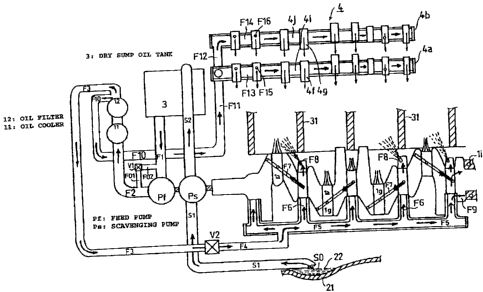
FIG. 10 shows a lubricating oil supply system according to the preferred
embodiment of the present invention.
As described earlier, two oil pumps Pf, Ps, that is the feed pump Pf and the
scavenging pump Ps, are juxtaposed on the oil pump shaft lq at the
leftward end lm of the crankshaft 1 as shown in FIGS. 4, 9, and the like.
The oil pump shaft lq is coaxial with, and rotated by being operatively
connected to, the crankshaft 1.
Referring to FIG. 7, a suction port PfA of the feed pump Pf communicates
with an opening 3c at a lower portion of the dry sump oil tank 3 via a
lubricating oil suction oil path Fl. A discharge port PfB of the feed pump
Pf communicates with the unit 10 representing the integrated structure of
the oil cooler 11 and the oil filter 12 via a lubricating oil supply path F2.
The lubricating oil supply path F2 provides communication between the
WH-12566/cs
CA 02497727 2008-03-28
WH-12566CA - 15 -
SN 2,497,727
oil cooler 11 at the downward portion of the unit 10 and the discharge port
PfB
of the feed pump Pf. Accordingly, driving the feed pump Pf causes the
lubricating oil in the dry sump oil tank 3 to be supplied to the unit 10.
The lubricating oil supply path F2 includes a branch oil path F01 (see FIG.
10). A
relief valve V1 (see also FIGS. 1 and 7) is disposed on the branch oil path
F01.
The relief valve V1 functions to regulate a lubricating oil supply pressure in
the
lubricating oil supply path F2. The lubricating oil that has flowed from the
relief
valve V1 is to be returned to the lubricating oil suction oil path Fl through
a
branch oil path F02 (see FIG. 10).
The lubricating oil is then supplied to the unit 10. The lubricating oil is
filtered
by the oil filter 12 and cooled by the oil cooler 11 in the unit 10. The
lubricating
oil is further supplied as follows as can be understood by referring to FIGS.
4, 7,
8, and 9. Specifically, the lubricating oil from a lubricating oil outlet port
of the
unit 10 is supplied to an oil gallery F5, camshafts 4a, 4b of the valve train
4, and
the like through the branch supply paths. The branch supply paths include
lubricating oil supply paths F3, F4 (see FIG. 7) to the oil gallery F5 and
lubricating oil supply paths F10, F11 (see FIG. 2) to the valve train 4.
A flow rate control valve V2 is disposed (see FIG. 9) in the lubricating oil
supply
paths F3, F4 serving as the branch supply paths to the oil gallery F5 that
communicates with the lubricating oil outlet port of the unit 10. The flow
rate
control valve V2 has a function with which an opening thereof is automatically
adjusted according to the supply pressure of the lubricating oil.
Specifically, the
flow rate control valve V2 is provided with a flow rate control function for
varying the flow rate according to rotation of the engine. More specifically,
the
opening of the control valve V2 is made small to suppress a supply amount of
the lubricating oil when the engine is run at low speed. The opening of the
control valve V2 is made large to increase the supply amount of the
lubricating
oil when the engine is run at high speed. Accordingly, the supply amount of
the
lubricating oil to the oil gallery F5 is throttled when the engine is run at
low
speed. A sufficient amount of the lubricating oil is thereby supplied to the
valve
train requiring a greater amount of lubricating oil. Disposition of the
control
CA 02497727 2005-02-18
-16-
valve V2 is achieved by using a joint 24 between the crankcase 20 and the
crankcase cover 23.
Referring to FIG. 4, the oil gallery F5 extends in parallel with the
crankshaft 1 at the downward portion thereof. The oil gallery F5 extends
to cover substantially an entire length of the crankshaft 1. A number of
paths and ports are brought into communication with the oil gallery F5 as
detailed in the following. Specifically, these paths and ports include: a
plurality of lubricating oil supply paths F6, F7 communicating with
journals 1g and crankpins la, to which connecting rods lb are connected,
of the crankshaft 1; lubricating oil injection ports F8 for inner wall
portions of the cylinder holes 31; and a lubricating oil supply path F9
communicating with the ball bearing 1i on the rightward end lh of the
crankshaft 1.
The lubricating oil supply paths F10, F11 communicating with the
camshafts 4a, 4b of the valve train 4 are so-called lubricating oil supply
paths for the exclusive use for the valve train 4. The lubricating oil from
the lubricating oil supply paths F10, F11 does not flow through the oil
gallery F5. As shown in FIG. 4, the lubricating oil supply path F10
branches off an oil outlet path of the unit 10, extends horizontally, is
routed through the joint 24 between the crankcase 20 and the crankcase
cover 23, and is communicated with the lubricating oil supply path F11.
The lubricating oil supply path F11 communicated with the lubricating oil
supply path F10 is bent substantially at right angles from the lubricating oil
supply path F10. The supply path F11 then extends upwardly along
opening portions 30A, 40A for the cylinder block 30 on the upper portion
of the crankcase 20 and the cam chain 4e of the cylinder head 40, and along
a water jacket 32 of the cylinder (see FIG. 4) inside the wall portion. The
lubricating oil supply path F11 is thereby communicated with lubricating
oil supply paths F13, F14 inside the camshafts 4a, 4b via a branch
lubricating oil supply path F12. The lubricating oil supply paths F13, F14
inside the two camshafts 4a, 4b include a plurality of apertures F15, F16
opening in each of cam surfaces.
WH-12566/cs
CA 02497727 2005-02-18
-17-
Reference is now made to the scavenging pump Ps juxtaposed with the
feed pump Pf on the oil pump shaft 1q. A pump suction port PsA (see FIG.
4) of the scavenging pump Ps is connected to an oil path S1 for sucking oil
accumulated in the bottom portion 21 of the crankcase 20 to be described
later. Referring to FIG. 4, the oil path S1 for sucking accumulated oil is
extended up to an oil sump 221ocated substantially at a central portion of
the bottom portion 21 of the crankcase 20 from the pump suction portion
PsA. There is provided an opening SO at an extended end of the oil path
S1. The opening SO having a function of sucking the accumulated oil faces
the oil sump 22.
The oil path S1 for sucking accumulated oil has a structure of being
communicated with the pump suction port PsA of the scavenging pump
Ps as detailed below. Specifically, the oil path S1 is extended from the oil
sump 22 substantially in parallel with the bottom portion 21 of the
crankcase 20. The oil path S1 is extended also in parallel with the
crankshaft 1 and the oil gallery F5 downward thereof.
Referring to FIG. 7, a discharge port PsB of the scavenging pump Ps is
communicated with an upper portion opening 3d of the dry sump oil tank
3 through an accumulated oil return oil path S2. The oil path S2 is
extended substantially obliquely upwardly toward the upper portion of the
dry sump oil tank 3 from the pump discharge port PsB in FIG. 7.
Accordingly, because of the structure of the oil paths S1, S2 having
communication with the scavenging pump Ps, the oil accumulated in the
bottom portion 21 of the crankcase is to be returned to the dry sump oil
tank 3 as the scavenging pump Ps is driven.
As the crankshaft 1 is rotated through drive of the internal combustion
engine E, the two oil pumps Pf, Ps, or more specifically, the feed pump Pf
and the scavenging pump Ps are driven. As shown in FIG. 7, driving the
feed pump Pf causes the lubricating oil in the dry sump oil tank 3 to be
pumped thereinto through the suction port PfA thereof by way of the
lubricating oil suction oil path F1. As the pressure of the feed pump Pf is
boosted, the lubricating oil is sent under pressure from the discharge port
PfB of the feed pump Pf.
WH-12566/cs
CA 02497727 2008-03-28
WH-12566CA - 18 -
SN 2,497,727
The lubricating oil sent under pressure from the discharge port PfB of the
feed
pump Pf is supplied through the lubricating oil supply path F2 to the unit 10
as
the integral structure integrating the oil cooler 11 with the oil filter 12.
The
supply pressure in the lubricating oil supply path F2 is regulated by the
relief
valve V1 disposed on the branch oil path F01 (see FIG. 10). The lubricating
oil
flowing out through a pressure regulating action by the relief valve Vl is
returned again to the lubricating oil suction oil path Fl through the branch
oil
path F02 (see FIG. 10).
The lubricating oil that has flowed into the unit 10 circulates therethrough.
During this period, the lubricating oil is filtered by the oil filter 12 and
cooled by
the heat exchanger included in the oil cooler 11. The lubricating oil, which
has
been filtered and cooled in the unit 10, is supplied to the oil gallery F5,
the
camshafts 4a, 4b of the valve train 4, and the like through the lubricating
oil
supply paths F3, F4 and lubricating oil supply paths F10, F11 (see FIG. 4).
The lubricating oil sent under pressure in the lubricating oil supply path F3
having communication with the oil gallery F5 pushes open the flow rate control
valve V2 (see FIG. 9) to flow through the lubricating oil supply path F4. The
lubricating oil is then supplied to the oil gallery F5. The lubricating oil
supplied
into the oil gallery F5 flows through the oil gallery F5 that is extended
along the
crankshaft 1 downward thereof (see FIG. 4).
The lubricating oil that has flowed through the oil gallery F5 flows therefrom
via
the lubricating oil supply paths F6, F7. The lubricating oil is then supplied
to the
journals 1g and the crankpins la, to which the connecting rods lb are
connected,
of the crankshaft 1. The lubricating oil is further supplied from the
lubricating
oil injection ports F8 to the inner wall portions of the cylinder holes 31 and
through the lubricating oil supply path F9 to the ball bearing 1i on the
rightward
end 1h of the crankshaft 1. The lubricating oil is thus served for lubrication
of
different parts of the engine (see FIG. 4).
The lubricating oil sent under pressure to the lubricating oil supply paths
F10,
F11 having communication with the camshafts 4a, 4b of the valve train 4 will
now be described. This part of the lubricating oil first flows
CA 02497727 2005-02-18
-19-
through the lubricating oil supply path F10 extending horizontally and
passing through the joint 24 between the crankcase 20 and the crankcase
cover 23. The lubricating oil then flows through the lubricating oil supply
path F11. The supply path F11 is bent substantially at right angles from the
supply path F10. The supply path Fl1 then extends upwardly along the
opening portions 30A, 40A for the cam chain 4e in the cylinder block 30
and the cylinder head 40, and along the water jacket 32 of the cylinder
inside the wall portion (see FIG. 4).
The lubricating oil that has flowed through the supply path F11 is
branched into two streams after the branch lubricating oil supply path F12
at the upper portion of the supply path F11. The oil then flows through
the lubricating oil supply paths F13, F14. The lubricating oil supply paths
F13, F14 serve as hollow hole portions 4i, 4j inside the corresponding one
of the two camshafts 4a, 4b, respectively. The two camshafts 4a, 4b are the
camshaft 4a on the intake side and the camshaft 4b on the exhaust side.
The oil then flows out through the plurality of apertures F15, F16 opening
in each of cam surfaces of the lubricating oil supply paths F13, F14. The oil
is thus served for lubricating and cooling the cam surface of cams 4f, 4g, a
tappet 4h, and the like (see FIGS. 4 and 8). The return oil after lubrication
is returned to the oil sump 22 at the bottom portion 21 of the crankcase 20
through a return oil path and the like not shown inside the wall portion
of the cylinder block 30.
Though not explicitly shown in the figures or explained, supply paths for
supplying drive units and the like of other auxiliaries are appropriately
provided. The lubricating oil that has been served for lubricating different
parts of the engine E as described above drips in the engine E and is
returned to the oil sump 22 at the bottom portion 21 of the crankcase 20 as
appropriately through return oil paths not shown (see FIG. 4).
As described in the foregoing, the lubricating oil is served for lubrication
of different parts mentioned above of the internal combustion engine E
and then drips or flows to the oil sump 22 at the bottom portion 21 of the
crankcase 20. That part of lubricating oil is pumped up from the suction
port PsA of the scavenging pump Ps through the oil path S1 for sucking
accumulated oil by the scavenging pump Ps, which is driven with the feed
WH-12566/cs
= CA 02497727 2005-02-18
-20-
pump Pf. The lubricating oil is then returned to and recovered in the dry
sump oil tank 3 through the accumulated oil return oil path S2, in which
a pump pressure is boosted in the scavenging pump Ps (see FIGS. 4 and 7).
The lubricating oil is again served for lubrication of different parts of the
engine E as described above through the aforementioned paths of
lubricating oil supply.
A cooling structure in the internal combustion engine E will now be
described. Referring to FIG. 6, the coolant pump Pw is disposed in the
cutout space portion Ela in the dry sump oil tank 3 disposed at the front
portion El of the internal combustion engine E. As described earlier, the
coolant pump Pw is drivingly rotated in synchronism with the rotation of
the crankshaft 1 through the chain Pwc mounted on the sprocket lk
disposed nearer the rightward end lh of the crankshaft 1 (see FIGS. 3 and
4) and the sprocket Pwb mounted on the coolant pump shaft Pwa (see
FIGS. 3 and 12).
As can be understood by referring to FIGS. 6 and 12, there is included a
coolant return path W1. The coolant return path W1 provides
communication between the coolant intake port PwAl of the coolant
pump Pw and a coolant outlet of the radiator 68 (see FIG. 1) not shown in
either FIG. 6 or 12 and disposed downward of the seat 64 of the snow
vehicle 60. There is also included a coolant supply path W2. The coolant
supply path W2 provides communication between the coolant discharge
port PwB of the coolant pump Pw and a coolant introduction port E01 for
introducing coolant to the engine E and located at the center of the front
portion El of the engine E. There is further included a coolant supply path
W3. The coolant supply path W3 includes the water jacket 32 and the like
for guiding the coolant introduced through the coolant introduction port
E01 located at the center of the front portion El of the engine E to areas
around the cylinder holes 31 of the engine E (see FIG. 11).
Further, there is included a coolant path W4. The coolant path W 4
provides communication between an outlet of the coolant supply path
W3, that is, a coolant exit port E02 for the coolant coming out of the engine
E. and a coolant inlet of the radiator 68. The coolant path W4 includes a
thermostat and a reservoir tank not shown and interposed therebetween.
WH-12566/cs
CA 02497727 2005-02-18
-21-
In addition, there is disposed a bypass coolant path W10 (see FIGS. 6 and
11) that branches off the thermostat. The bypass coolant path W10 is for
cooling (warm-up operation) when the coolant temperature is low. The
bypass coolant path W10 is communicated with a suction port PwA2 (see
FIG. 6) of the coolant pump Pw.
The coolant introduction port E01 for introducing coolant to the engine E
is located substantially at the central portion of the cylinder block 30 in
the
vertical direction. The coolant exit port E02 for the coolant coming out of
the engine E is, on the other hand, located at an upper portion of the
cylinder block 30 in the vertical direction. Accordingly, the coolant
introduction port E01 and the coolant exit port E02 are disposed in the
cylinder block 30 in a vertical positional relationship relative to each other
(see FIG. 6).
This is further disposed a coolant supply path W20 at a position near a
connection between the coolant supply path W2 and the coolant
introduction port E01 (see FIG. 6). The coolant supply path W20 connects
to the coolant introduction pipe 11a having communication with a
coolant inlet of the oil cooler 11. In addition, there is also disposed a
coolant path W21 (see FIG. 11) that connects to the coolant exhaust pipe
11b of the oil cooler 11. Though not shown in the figures, the coolant path
W21 is communicated with the coolant path W4 providing
communication between the coolant exit port E02 and the coolant inlet of
the radiator 68.
The coolant pump Pw is rotatably driven by being operatively connected
with the rotation of the crankshaft 1 as the internal combustion engine E
is started. Coolant cooled by the radiator 68 is then drawn into the coolant
pump Pw through the coolant intake port PwA1 thereof. Because of the
boosted pump pressure in the coolant pump Pw, the coolant is delivered
from the coolant discharge port PwB of the coolant pump Pw. The coolant
is then supplied to the coolant supply path W3 (see FIG. 11) including the
water jacket 32 and the like of the engine E after having flowed through
the coolant supply path W2 and by way of the coolant introduction port
E01 (see FIG. 6) for introducing coolant to the engine E at the center of the
front portion El of the engine E.
WH-12566/cs
CA 02497727 2005-02-18
-22-
The coolant supplied to the coolant supply path W3 of the engine E flows
into the water jacket 32 surrounding the cylinder holes 31 forming a
principal part of the coolant supply path W3. While flowing through the
water jacket 32 and the coolant supply path not shown inside the cylinder
head 40, the coolant absorbs heat. The heated coolant is then discharged
from an outlet of the coolant supply path W3 of the engine E. More
specifically, the heated coolant is discharged out of the engine E from the
coolant exit port E02 for the coolant coming out of the engine E. The
coolant thereafter flows through the coolant path W4 having
communication with the coolant exit port E02 and connecting to the
radiator 68 (see FIG. 11). The coolant is then introduced into the radiator
68 through an inlet thereof at an upper portion thereof.
The heated coolant introduced into the radiator 68 circulates through the
radiator 68. During circulation of the heated coolant through the radiator
68, heat is drawn off from the coolant and the coolant is cooled. The
cooled coolant is again drawn into the coolant intake port PwA1 of the
coolant pump Pw through the coolant return path W1 (see FIG. 6).
Circulating through the aforementioned coolant supply path, the coolant
is designed to cool different parts of the engine E.
The present invention as embodied in the preferred embodiment has the
aforementioned structure. The present invention achieves the following
effects that are unique to the preferred embodiment of the present
invention.
Specifically, the lubricating oil supply paths F10, F11 for the exclusive use
for the valve train 4 branch off a point near the outlet of the unit 10. The
lubricating oil supply paths F10, F11 circumvent the oil gallery F5. The
lubricating oil is therefore directly supplied to the camshafts 4a, 4b in the
valve train 4. Accordingly, a pressure drop that would otherwise tend to
occur during supply of the lubricating oil to the valve train 4 can be
completely eliminated. Positive and effective lubrication in the valve
train 4 can therefore be achieved.
WH-12566/cs
CA 02497727 2008-03-28
WH-12566CA - 23 -
SN 2,497,727
The flow rate control valve V2 for regulating the supply amount of the
lubricating oil according to the operating condition of the engine E is
disposed
on the lubricating oil supply path F4 going to the oil gallery F5. When the
engine is run at low speed, the flow rate control valve V2 is substantially
throttled. This suppresses the supply amount of the lubricating oil to the oil
gallery F5. While, a greater amount of lubricating oil corresponding to the
suppressed amount of oil to the oil gallery F5 is supplied to the valve train
4. A
sufficient amount of the lubricating oil is therefore supplied to the valve
train 4
despite a condition, in which a lubricating oil supply pressure is low with
the
engine E running at low speed.
The lubricating oil supply paths F10, F11 for the exclusive use for camshafts
4a,
4b of the valve train 4 are simply structured. The paths F10, F11 basically
include the supply path F10 extending in the horizontal direction and the
supply
path F11 having communication with the supply path F10 and extending
substantially in the vertical direction. This simple structure ensures a
smooth
supply of the lubricating oil to the valve train and suppresses a drop in the
lubricating oil supply pressure. The structure thereby secures a sufficient
amount of the lubricating oil for lubrication of the valve train. Lubrication
of the
camshafts 4a, 4b and the valve train 4 including the camshafts 4a, 4b can be
positively and effectively performed.
Further, the lubricating oil supply paths F10, F11 for the exclusive use for
the
valve train 4 extend along the opening portions 30A, 40A for the cam chain 4e
and along the water jacket 32 of the cylinder block 30. The lubricating oil
can
maintain a sufficiently cooled state based on the advantageous cooling
performance retention structure when supplied to the camshafts 4a, 4b of the
valve train. Effective lubrication and cooling in the valve train 4 can
therefore
achieved.
The valve train lubricating structure in the internal combustion engine
mounted
on the snow vehicle according to the present invention is applicable to
internal
combustion engines for various types of vehicles and for other purposes.
Although various preferred embodiments of the present invention have been
described herein in detail, it will be appreciated by those skilled in the
CA 02497727 2005-02-18
-24-
art, that variations may be made thereto without departing from the spirit
of the invention or the scope of the appended claims.
WH-12566/cs