Note: Descriptions are shown in the official language in which they were submitted.
CA 02498271 2005-03-09
WO 2004/024039 PCT/US2003/028878
1135-5
IMPLANT MANIPULATION AND STORAGE TOOLS
BACKGROUND
CROSS REFERENCE TO RELATED APPLICATIONS;
The present disclosure claims priority to U.S. Provisional Application Serial
No.
60/410,458, filed September 13, 2002, entitled Implant Manipulation and
Storage Tools and
U.S. Provisional Application Serial No. 60/423,864, filed November 5, 2002,
entitled Implant
Folding and Storage Device, the entire disclosures of which are incorporated
by reference
herein.
1. Technical Field
The present disclosure relates to tools for flexible implants, and more
particularly, to
manipulation and storage tools for use with flexible gel implants.
2. Background of Related Art
Certain spinal conditions can result in severe pain to a patient as a result
of a
protruding intervertebral disk or a degenerative disk positioned between
adjacent vertebrae.
Various surgical procedures are known to attempt to correct the appropriate
spacing
between the adjacent vertebrae and minimize the impact of the damaged disk on
the adjacent
spinal cord. One such solution includes the affixation of one or more external
rods to the
adjacent vertebrae to fix the adjacent vertebrae in a proper spacing and
retain them in that
position. Alternatively, various internal devices have been designed which are
positioned
within an excised portion of the intervertebral disk and are configured to
fuse or lock up the
adjacent vertebrae in order to relieve any pressure on the spine. While both
these procedures
are quite common, they do have the disadvantage of fusing or locking the
adjacent vertebrae
resulting in reduced or limited flexibility in that area of the spine as well
as taking an
extended period of recovery.
CA 02498271 2005-03-09
WO 2004/024039 PCT/US2003/028878
1135-5
Another known procedure for relieving pressure on the spine, due to a
defective
intervertebral disk, involves the placement of a partial or whole replacement
implant or disk
in the intervertebral disk space which allows flexibility of the spine to be
maintained while
maintaining the adjacent vertebrae in their proper spacing or disk height.
In these procedures, the disk implant is typically in a partially hydrated and
flexible
state and is manipulated by various hand instruments or tools to configure it
into a folded or
compressed shape state while it is being inserted into the disk space. Once
the compressed
implant is put into the disk space it is allowed to expand or regain its
original shape and re-
hydrate to an appropriate restored disk height.
Problems occur during manipulation of the disk into a compressed state and in
trying
to maintain that particular compressed state while the disk is being manually
inserted into the
intervertebral disk space. Proper and precise placement of the disk in a
position to re-hydrate
to a proper height is also one of the difficulties in performing the
substitute disk procedure
manually. Thus, it would be desirable to have a tool which could precisely
manipulate the
partially dehydrated implant into a specific compressed shape. It would
further be desirable
to take the compressed disk and load it into a storage member for relatively
quick use and
precise insertion. Additionally, it would be desirable to have an insertion
tool configured to
receive the stored and compressed disk, precisely position it adjacent the
vertebrae and insert
it between the vertebrae so that it can re-hydrate and expand to a proper disk
height.
SUMMARY
There is disclosed a manipulation and storage tool for receiving a partially
dehydrated
flexible implant, manipulating it to a smaller or compressed overall size and
inserting it into a
storage or sleeve device. The manipulation and storage tool generally includes
a guide
member or assembly and a manipulation assembly movably mounted with respect to
the
guide assembly. The guide assembly includes a chamber or longitudinal
throughbore and an
CA 02498271 2005-03-09
WO 2004/024039 PCT/US2003/028878
1135-5
opening or slot for receipt of a disk so that the disk extends across the
throughbore.
Preferably, a storage or sleeve holder is mounted to the distal end of the
guide assembly to
frictionally engage and retain a storage member or sleeve therein.
The manipulation assembly generally includes a drive member having an
elongated
outer tube extending distally into the guide assembly. A pair of manipulation
members or
pins extend distally from the distal end of the outer tube and are positioned
adjacent the slot
to receive the disk therebetween. The drive member has a circumferential track
including a
level portion extending approximately 180° around the drive member and
an angled portion
extending from the distal end of the drive member towards a proximal end of
the drive
member the remaining 180° around the drive member. A longitudinal
portion connects the
level portion of the track with the proximal end of the angle portion of the
track. The
movement of the manipulation assembly relative to the guide assembly is
controlled by a
drive rod fixedly mounted to a proximal end of the guide assembly and having a
drive pin
which resides in the track of drive member. Thus, as the drive member is
rotated an initial
180° the drive pin rides in the level portion of the track to rotate
the drive pins and twist the
disk positioned therebetween into a smaller overall shape. Subsequently, as
the drive
member is rotated the additional 180° the drive pin rides in the angled
portion of the track
thereby drawing the manipulation assembly distally such that the now folded
disk is inserted
into the sleeve retained on the end of the guide assembly.
Preferably, the track has an extension extending proximally from the
longitudinal
portion such that advancement of the pin distally in the extension partially
ejects the sleeve
from the sleeve holder. Preferably, the sleeve holder is provided with a
securing screw or
knob which frictionally compresses the sleeve holder about the sleeve and upon
release of the
knob releases the friction on the sleeve.
CA 02498271 2005-03-09
WO 2004/024039 PCT/US2003/028878
1135-5
Manipulation assembly is also provided with a plunger assembly consisting of a
plunger proximally biased relative to the drive member by a spring and a cap
mounted at the
distal end of the plunger. Once the disk has been manipulated to a smaller
size and inserted
into the sleeve, the plunger can be depressed to move the cap along the pins
and against the
sleeve to eject the sleeve from the device.
There is also disclosed an insertion tool for use with the now assembled
sleeve and
manipulated disk. The insertion tool generally includes an outer tube having a
throughbore
and an outer tube extension extending distally and having a reduced inner
diameter which
forms a step between the outer tube and the outer tube extension. This step is
provided to
retain the sleeve within the bore of the outer tube and position the
manipulated disk in
alignment with the bore of the extension. An inserter is provided to extend
through the bore
of the outer tube and engage and eject the disk into a prepared disk space.
An alternative embodiment of a manipulation tool is disclosed which is
provided to
manipulate the disk into a generally elliptical or D-shape for use with an
oval cross-section
sleeve. The alternate tool includes generally a base and a pair of upwardly
extending side
supports and a center support movably mounted within the base. A pair of side
drive
members as well as a vertical drive member are also provided. The disk is
generally
positioned on top of the side supports and center support and the vertical
driver driven to
form the disk into an initially C-shaped. Subsequently the side drivers are
moved radially
inwardly to fold the implant into a generally D-shape.
Methods of using the storage and insertion tool, the storage and manipulation
tool, the
insertion tool, are also disclosed herein.
There is also disclosed a further alternative embodiment of an implant folding
and
storage device to fold an implant and store it for use within an insertion
device. The
disclosed implant folding and storage device generally includes an implant
folding device and
CA 02498271 2005-03-09
WO 2004/024039 PCT/US2003/028878
1135-5
an implant transfer device and implantation tube configured to be attached to
the implant
folding device.
The implant folding device generally includes two longitudinally movable jaws
mounted on guide members. The jaws define a recess therebetween for receipt of
an implant.
A drive member is provided to move the jaws relative to each other in order to
reduce the size
of the recess and compress or fold an implant positioned within the recess.
The implant transfer device is provided to move the folded implant from within
the
implant folding device and into the implantation tube. The implant transfer
device generally
includes an outer tube having a locking member at a distal end. The locking
member is
provided to affix the implant transfer device to the implant folding device. A
pusher extends
through the tube and is moved by a drive member to force the folded implant
out of the.
implant folding device.
The disclosed implantation tube is provided to be attached to the implant
folding
device and to store the folded implant. The implantation tube is configured to
receive the
folded implant by means of the implant transfer device. The implantation tube
is attached to
the implant folding device by engagement of recesses on the implantation tube
with posts on
the implant folding device.
A method of using the implant folding and storage device to fold and store an
implant
is also disclosed. An implant is positioned within the recess between the jaws
and the jaws
are compressed to fold the implant within the recess. The recess may be
configured to fold
the implant into a generally C shape or other desired folded configuration.
The transfer
device is affixed to the folding device and actuated to drive the folded
implant into the
implantation tube to sleep. Thereafter the implantation tube may be removed
and stored for
use with insertion instrumentation.
CA 02498271 2005-03-09
WO 2004/024039 PCT/US2003/028878
1135-5
There is also disclosed a novel transfer tube for receipt of a folded implant
and for use
with a surgical instrument assembly. The transfer tube includes a transfer
sleeve for receipt
of the folded implant and first and second nuts rotatably mounted upon the
sleeve. The first
nut is configured to engage the distal end of a surgical instrument and the
second nut is
configured to cam a lock member against a working sleeve.
There is also disclosed a novel surgical instrument configured to drive a
folded
implant into the body which generally includes a body portion have a fixed
handle and a
movable handle. The surgical instrument includes a pusher rod movable through
the body
portion in response to actuation of the movable handle. Ratchet mechanisms are
provided to
biased the pusher rod in a distal direction and prevent inadvertent retraction
of the rod.
A unique surgical instrument assembly is also disclosed which includes the
novel
surgical instrument and transfer tube, along with a working sleeve.
BRIEF DESCRIPTION OF THE DRAWINGS
Various embodiments are described below with reference to the drawings
wherein:
FIG. 1 is a perspective view of a manipulation and storage tool, sleeve and
implant;
FIG. lA is an end view of the manipulation and storage tool;
FIG. 2 a perspective view of the manipulation assembly of the tool of FIG. 1;
FIG. 3A is a perspective view of the manipulation and storage tool with the
manipulation assembly rotated 180° relative to a guide assembly;
FIG. 3B is a perspective view of the manipulation and storage tool with the
manipulation assembly rotated an additional 180° relative to the guide
assembly;
FIG. 3C is a perspective view of the manipulation and storage tool with a
plunger
depressed to eject a sleeve containing the implant out of the manipulation and
storage tool;
FIG. 4A is an end view of an alternative embodiment of a implant manipulation
tool;
CA 02498271 2005-03-09
WO 2004/024039 PCT/US2003/028878
1135-5
FIG. 4B is an end view of the tool of FIG. 4A initially folding an implant;
FIG. 4C is an end view of the tool of FIG. 4A further folding the implant;
FIG. 4D is an end view of the folded implant inserted in a sleeve; and
FIG. 5 is a side view, shown in section, of an insertion tool for receiving a
sleeve and
inserting a folded implant into an intravertebral disk space;
FIG. 6 is a top plan of another embodiment of an implant folding and storage
device;
FIG. 7 is a side view of an implant folding device;
FIG. 8 is a side view of an implant transfer device;
FIG. 9 is a side view, partially shown in section, of the implant transfer
device;
FIG. 10 is another side view of the implant transfer device;
FIG. 11 is a side view of a drive member of the implant transfer device;
FIG. 12 is a side view of an implantation tube;
FIG. 13 is a perspective view of the implant folding and storage device;
FIG. 14 is a perspective view of the implant folding device with a implant
being
inserted;
FIG. 15 is a side view of the implant folding device prior to compression of
the
implant;
FIG. 16 is a top plan review of the impact plant folding device during
compression of
the implant;
FIG. 17 is a side view of the implant folding device with the implant transfer
device
attached thereto;
FIG. 18 is a top plan review of the implant being transferred from the implant
folding
device to the implantation tube;
FIG. 19 is a side view illustrating the folded implant contained in the
implantation
tube;
7
CA 02498271 2005-03-09
WO 2004/024039 PCT/US2003/028878
1135-5
FIG. 20 is a perspective view of a modified implant folding device,
alternative pusher
and transfer tube;
FIG. 21 is a perspective view of the modified implant folding device and
transfer tube
illustrating alternative connection structure;
FIG. 22 is a perspective view of the transfer tube being attached to the
distal end of an
implant insertion instrument;
FIG. 23 is a side view, partially shown in section, of the transfer tube prior
to
affixation to a working sleeve;
FIG. 24 is a perspective view of the working sleeve being connected to the
transfer
tube;
FIG. 25 is a perspective view of the working sleeve being affixed to the
transfer tube;
FIG. 26 is a side elevation view of a surgical instrument or implant insertion
tool;
FIG. 27 is an enlarged side view of the handle section of the implant
insertion tool
partially shown in section; and
FIG. 28 is a side cross-sectional view of another preferred embodiment of the
presently disclosed transfer tube.
DETAILED DESCRIPTION OF PREFERRED EMBODIMENTS
The preferred embodiments of the devices and methods disclosed herein relate
to
tools for receiving a fully hydrated or fully or partially dehydrated,
flexible intervertebral
implant and manipulating the implant such that the implant is reduced in
overall size and
inserted into a storage member or sleeve retained in the tool.
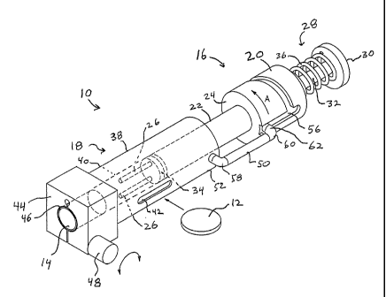
Referring now to FIG. 1, a manipulation and storage tool 10 is provided to
receive a
flexible implant 12 and a manipulate implant 12 such that it can be inserted
into a storage
member or sleeve 14 which is retained in manipulation and storage tool 10.
Manipulation
CA 02498271 2005-03-09
WO 2004/024039 PCT/US2003/028878
1135-5
and storage tool 10 generally includes a manipulation assembly 16 which is
configured to
manipulate flexible implant 12 into a smaller configuration which may be
compressed or
folded, etc., such that it may be inserted into sleeve 14. Manipulation and
storage tool 10
additionally includes a guide assembly 18 for guiding the flexible implant 12
into sleeve 14.
Manipulation assembly 16 includes a drive member 20 having an outer tube 22
extending distally from distal end 24 of drive member 20. A pair of
manipulation members
or pins 26 are affixed to a distal end of outer tube 22. Manipulation assembly
16 additionally
includes a plunger assembly 28 having a plunge cap 30 and a plunge rod 32
extending
distally from plunge cap 30. A pusher 34 is affixed to a distal end of plunge
rod 32 to
facilitate ejecting sleeve 14 from manipulation and storage tool 10.
Preferably plunger
assembly 28 is biased in a pxoximal direction relative to drive member 20 by a
spring 36
interposed between plunge cap 30 and drive member 20.
Guide assembly 18 includes a guide tube 38 having a bore 40 therethrough. One
or
more slots 42 are provided on guide tube 38 and intersect bore 40. Slots 42
are provided to
receive flexible implant 12 and position it across bore 40. A sleeve holder 44
is affixed to a
distal end of guide tube 38 and includes a bore 46 for receipt retention of
sleeve 14. A lock
knob 48 is provided to reduce the diameter of bore 46 so as to fractionally
engage sleeve 14
and retain it within bore 46. Referring to FIG, lA, specifically, sleeve
holder 44 is sectioned
by slot 64 and a threaded rod 68 extends from cap 66 across slot 44a.
Guide assembly 18 and manipulation assembly 16 are interconnected by a drive
rod
50. Drive rod 50 extends between a proximal end 52 of guide tube 38 and distal
end 24 of
drive member 20. Specifically, drive member 20 is provided with a
circurnferential track 56.
A distal end 58 of drive rod 50 is connected to proximal end 52 of guide 38. A
proximal end
60 of drive rod 50 is mounted with respect to drive member 20. Specifically, a
drive pin 62
formed at the proximal end 60 of drive rod 50 is configured to be retained in
and ride within
CA 02498271 2005-03-09
WO 2004/024039 PCT/US2003/028878
1135-5
track 56 such that manipulation assembly I6 moves relative to guide assembly
18 in response
to rotation of drive member 20.
As noted above, manipulation assembly 16 is pxovided to manipulate flexible
implant
12 into a smaller configuration so that it may be inserted within a storage or
sleeve 14. This
occurs in response to rotation of manipulation assembly 16, and in particular
drive number
20, relative to guide assembly 18. As discussed above, drive pin 62 located at
proximal end
60 of drive rod 50 is configured to reside within and move within track 56.
Referring now to FIG. 2, track 56 is provided with a longitudinal portion 76
intersecting a Level portion 78 at distal end 54 of drive member 20. Level
portion 78 extends
circumferentially around drive member 20 approximately 180° where it
intersects an angled
portion 80 of track 56. Angled portion 80 extends circumferentially
180° from a location
adjacent the distal end 54 of drive member 20 proximally to intersect
longitudinal portion 76
at a position adjacent proximal end 72 of longitudinal portion 76. An
extension 74 of
longitudinal portion 76 extends proximally from longitudinal portion 76.
Drive membex 20 is provided with a longitudinal bore 82 which connects to a
longitudinal bore 84 in outer tube 22. As noted above, plunger assembly 28
includes a
plunge rod 32. Plunge rod 32 extends through bores 82 and 84 and drive member
20 and
outer tube 22, respectively. Plunger rod 32 is provided with a plunger rod
extension 86
which extends through bore 84 and is affixed to pusher 34 at a distal end of
plunge rod
extension 86. Bores 88 formed in pusher 34 accommodate pins 26 such that upon
depression
of plunge cap 30, pusher 34 rides distally along pins 26 to engage and expel
sleeve 14 from
manipulation and storage tool 10.
In using manipulation and storage tool 10 to reduce the overall size of a
flexible
implant 12 and insert it into a sleeve I4 for storage, tool IO is initially
positioned with
manipulation assembly 16 in a proximal most position with respect to guide
assembly 18.
CA 02498271 2005-03-09
WO 2004/024039 PCT/US2003/028878
1135-5
Plunger assembly 28 is biased to a proximal most position with respect to
drive member 20
by spring 36. In this position, drive pin 62 is located at the distal end of
longitudinal portion
76 of circumferential track 56. Pins 26 are positioned adjacent slot 42 in a
position to receive
disk 12 therebetween.
Referring to FIGS. 1 and lA, a bore 46 of sleeve holder 44 is initially in a
relaxed
position for sliding receipt of sleeve 14. Sleeve 14 is positioned within bore
46 and lock
knob 48 is rotated such that threaded rod 68 is rotated to reduce slot 64
thereby frictionally
engaging sleeve 14 within bore 46.
Implant 12 is inserted through 42 such that implant 12 resides within bore 40
and
between pins 26.
To fold implant 12 into a generally S-shaped configuration drive member 20 is
rotated
to move drive pin 62 along level portion 78 of circumferential track 56
approximately 180°.
This rotates pins 26 causing them to engage disk 12 and form it into a
generally S-shape as
best seen in FIG. 3A. It should be noted that other shapes such as G-shape or
oval, etc. can
be provided based on the configuration of the pins 26.
Referring to FIG. 3A, once disk 12 has been manipulated into a generally S-
shape,
drive member 20 is rotated an additional 180° such that drive pin 62
advances up angled
portion 80 of circumferential track 62 an additional 180°. This
movement draws
manipulation assembly 16 distally relative to guide assembly 18. As
manipulation assembly
16 moves distally pins 26 and outer tube 22 carry the now S-shaped disk 12
distally to a
position within sleeve 14.
Referring now to FIG. 3B, in order to eject the now assembled sleeve 14 and
disk 12
from tool 10, knob 48 is rotated to relax slot 64 such that bore 46 expands
and releases sleeve
14. Drive member 20 is advanced an additional distal amount such that drive
pin 62 moves
into extension 74 thereby moving the entire manipulation assembly 16 distally
a slight
11
CA 02498271 2005-03-09
WO 2004/024039 PCT/US2003/028878
1135-5
amount to engage sleeve 14 and move sleeve 14 slightly distally within bore 46
to relieve any
frictional engagement between walls of sleeve 14 and bore 46.
Referring now to FIG. 3C, plunger assembly 28 is manipulated to eject sleeve
14 and
disk 12 from tool 10. Specifically, plunge cap 30 and plunge rod 32 are moved
distally
against the bias of spring 36 to drive pusher 34 distally over pins 26. This
engages pusher 34
with sleeve 14 and moves sleeve 14 distally. Pusher 34 slides along pins 26 to
push implant
12 and sleeve 14 distally. This ensures pusher 34 disengages any frictional
contact between
implant 12 and pins 26 as sleeve 14 is being ejected from tool 10.
Once flexible disk 12 has been inserted into sleeve 14 by use of manipulation
and
storage tool 10, the assembled sleeve 14 and disk 12 maybe stored for a period
of time until
needed. As noted, various type, sizes and compositions of implants 12 maybe
provided to a
surgeon so that he or she can choose between various sizes and configurations
of implants
during an operation.
Referring now to FIG. S there is illustrated an insertion tool 100 for use
with the now
loaded or combined sleeve 14 and gel disk or implant 12. Insertion instrument
100 is
configured to the position adjacent the opening in the disk space and utilized
to eject the gel
disk 12 from sleeve 14 and into the disk space. Specifically insertion tool
100 includes an
outer tube 102 defining a throughbore 104. An outer tube extension 106 having
an outer
diameter slightly less than or equal to the inner diameter of bore 104 extends
from a distal
end 108 of outer tube 102. Outer tube extension 106 defines a bore 110 which
has an inner
diameter substantially equal to the inner diameter of sleeve 14. By using the
reduced
diameter outer tube extension 106 a proximal edge 112 of outer tube extension
106 forms a
step or stop against which sleeve 14 can rest and be restrained within bore
104 of outer tube
102.
12
CA 02498271 2005-03-09
WO 2004/024039 PCT/US2003/028878
1135-5
Insertion tool 100 additionally includes an inserter 120 which is configured
to be
slidingly received through opening 118 within bore 104 of outer tube 102.
Preferably, the
diameter of inserter 120 is substantially equal to the diameter of bore 104 to
ensure a precise
sliding fit with little wobble. Inserter 120 has a reduced diameter portion
122 extending
distally from a distal end 124 of inserter 120. The reduced diameter portion
forms a step 126.
The outer diameter of reduced diameter portion 122 is smaller in diameter than
the inner
diameter of sleeve 14. However, the outer diameter of inserter 120 is greater
in diameter
than the inner diameter of outer tube extension 106 such that upon distal
advancement of
inserter 120 within outer tube 102 step 126 engages proximal edge 112 thereby
preventing
any further forward motion. The outer diameter of reduced diameter portion 122
is smaller
than the inner diameter of sleeve 14 so as to allow reduced diameter portion
122 to push or
eject implant 12 through bore110 and into an invertebral disk space.
While not specifically illustrated, the use of insertion tool 100 to receive a
loaded
sleeve 14 and disk 12 and to insert disk 12 into an intervertebral disk space
will now be
briefly described. Initially the vertebrae and damaged disk is accessed using
known surgical
procedures. The annulus of the intervertebral disk is then punctured or
excised to expose the
nucleus and a portion of the nucleus material is removed, preferably without
trauma to the
vertebral end plates, resulting in an intervertebral disk space. Various
instruments may be
utilized to determine the proper restored height for the intervertebral disk
spacing. Once the
proper height is determined the surgeon can choose between the proper size
disk 12 to be
inserted into the intervertebral disk space. As noted above, the
intervertebral disks and
sleeves 14 may be provided to the surgeon in varying heights either
preassembled or
assembled during the surgery using manipulation and storage tool 10. Once the
proper
loaded sleeve 14 and disk 12 are obtained, they are assembled in insertion
tool 100 by
passing loaded sleeve 14 through opening 118 and into bore 104 of outer tube
102. Loaded
13
CA 02498271 2005-03-09
WO 2004/024039 PCT/US2003/028878
1135-5
sleeve 14 slides within bore 104 distally until a distal-most edge of sleeve
14 contacts
proximal edge 112 of extension 106. This places disk 12 in alignment with bore
110 of
extension 106. Thereafter, inserter 120 is positioned through opening 118 and
into bore 104
tool position just proximal of disk 12.
Once insertion tool 100 has been loaded with sleeve 14 and disk 12, insertion
tool 100
is positioned such that extension 106 enters the annulus of the disk space and
a distal-most
edge of distal end 108 is adjacent to and contacts the adjacent vertebra
spanning the now
excised intervertebral disk space. Once properly positioned to the surgeon's
satisfaction,
inserter 120 can be advanced distally to cause reduced diameter portion 122 to
engage disk
12 and drive disk 12 through sleeve 14 and bore 110 in extension 106 and into
the
intervertebral disk space. As noted above, step 126 in inserter 120 engages a
proximal- most
edge 112 of extension 106 to limit the forward advancement of inserter 120
within outer tube
102. Once disk 12 has been properly positioned within the intervertebral disk
space, inserter
100 is removed from the disk space and the partially dehydrated disk 12 is
allowed to re-
hydrate and expand to its proper circular or disk shaped orientation and
enlarged to the proper
height to maintain the restored disk spacing as desired.
Referring now to FIG. 4A there is disclosed an alternate embodiment of a
manipulation tool for forming an implant 12 into a generally folded or
elliptical shape.
Specifically, manipulation tool 140 generally includes a base 142 having a
pair of side
supports 144 extending vertically up from base 142. A T-shaped center support
146 is
movably mounted with respect to base 142. horizontal side drivers 148 are
provided
adjacent side supports 144 to fold outer edges of implant 12. Tool 140 also
includes a
vertical driver 150 positioned opposite center support 146.
In use, partially dehydrated gel disc or implant 12 is initially positioned on
top of
center support 146 and side supports 144.
14
CA 02498271 2005-03-09
WO 2004/024039 PCT/US2003/028878
1135-5
Referring to FIG. 4B, vertical driver 150 is driven downwardly against implant
12 and
center support 146 driving center support 146 downwardly such that side
support 144, fold
outer edges 12a and 12b of implant 12 about vertical driver 150.
Referring to FIG. 4C, once edges 12a and 12b have been folded to in a vertical
position side drivers 148 move radially inwardly to fold edges 12a and 12b
into a generally
block-C or elliptical shape.
Once implant 12 has been so formed by vertical driver 150 moving in an X
direction
and side drivers 148 moving in a Y direction, an ejector not shown may be
advanced in the Z
direction to eject folded implant 12 out of manipulation tool 140. Preferably
folded implant
12 is ejected or inserted into an over sleeve 152 (FIG. 4D) for use in a
similar manner to that
of combined sleeve 14 and S-shaped implant 12 hereinabove.
FIGS. 6 and 7 illustrate an alternate embodiment of the presently disclosed
implant
folding and storage device shown generally as device 210. Device 210 includes
an implant
folding device 212, an implant transfer device 214, and an implantation
storage tube 216.
Implant folding device 212 includes a first jaw 218, a second jaw 220 and a
drive
member 222. First and second jaws 218 and 220 are movably supported in
relation to each
other on four guide members 224. Alternately, two guide members may be used. A
first end
224a of guide members 224 is axially fixed to first jaw 218. A second end 224b
of guide
members 224 is axially fixed to a support block member 226. Second jaw 220
includes a
plurality of longitudinal throughbores 225 (FIGS. 13 and 14) dimensioned to
slidably receive
guide members 224. Second jaw 220 is slidably positioned on guide members 224
between
first jaw 218 and support block 226. Drive member 222 includes a threaded
screw portion
228 and a rotation knob 230 fixedly secured to a proximal end of screw portion
228. Support
block 226 includes threaded bore 227 (FIG. 13) dimensioned to rotatably
receive screw
portion 228 of drive member 222. Preferably, the distal end of screw portion
228 is axially
CA 02498271 2005-03-09
WO 2004/024039 PCT/US2003/028878
1135-5
fixed but rotatable with respect to second jaw 220. Alternately, the distal
end of screw
portion 228 may abut against a sidewall of jaw 220.
In use, when rotation knob 230 is rotated to turn screw portion 228 within the
threaded bore in support block 226, screw portion 228 translates axially in
relation to support
block 226 to move second jaw 220 in relation to first jaw 218 between spaced
and
approximated positions. Although implant folding device 212 is illustrated as
having a drive
member in the form of a screw portion, it is envisioned that other known drive
members or
assemblies may also be used to move the first jaw member in relation to the
second jaw
member, e.g., ratchet drive mechanisms, levers, pneumatic pistons, etc.
First and second jaws 218 and 220 of implant folding device 212 preferably
have a
substantially L-shaped configuration including a longitudinally extending leg
232 and a
transversely extending leg 234. When jaws 218 and 220 are in an approximated
condition,
the jaws 218 and 220 interengage to define a substantially rectangular shape.
Alternately, the
jaws may assume different configurations including circular, square,
triangular, etc. Each
jaw includes a substantially semi-circular recess 238 formed along an inner
wall 236 of
longitudinally extending leg 232. Walls 236 of legs 232 and semi-circular
recesses 238
together define a receiving chamber 240 for receiving a flexible implant (not
shown). When
the jaws are fully approximated, recesses 238 define a circular bore. It is
envisioned that
recesses 238 may be defined by removable plates which can be selectively
replaced to change
the diameter of the bore defined by recesses 238. Such would allow folding
device 210 to be
used with different size flexible implants.
In use, when a flexible implant is positioned within receiving chamber 240 and
drive
member 222 is actuated to approximate jaws 218 and 220, the flexible implant,
which may
have a normally rectangular or circular configuration, is folded, via
engagement with semi-
circular recesses 238, into a circular or cylindrical configuration. It is
envisioned that the
16
CA 02498271 2005-03-09
WO 2004/024039 PCT/US2003/028878
1135-5
configuration of recesses 238 may be changed to provide different fold
patterns for the
flexible implant, e.g., S-shape, etc.
Referring to FIGS. 8-1 l, transfer device 214 includes an outer tube 242
having an
elongated longitudinal slot 244 formed therein. A first end 242a of tube 242
is flared
outwardly (FIG. 9). A pair of rings 246 and 248 are secured to first end 242a
of tube 242.
Rings 246 and 248 each have a knurled outer surface 250 to facilitate gripping
of the device.
Ring 246 includes an internally threaded bore 252 and is positioned on one
side of flared first
end 242a of tube 242. Ring 248 is positioned about tube 242 on an opposite
side of flared
first end 242a. Rings 246 and 248 are secured together, e.g., clamped about
flared end 242a
of tube 242, to secure the ring assembly to the first end of outer tube 242.
A locking member 254 is secured to a second end of outer tube 242. Locking
member 254 includes a proximally threaded extension 254a which is dimensioned
to
threadably engage the internal threads of a nut 256. The second end of outer
tube 242 also
includes an outwardly flared portion 242b which is clamped between locking
member 254
and nut 256 to secure the locking member to the second end of outer tube 242.
Locking member 254 includes a pair of hook portions 258, each defining a
recess 260.
Recesses 260 are dimensioned to receive screws 264 supported on implant
folding device 212
(FIG. 7) to secure implant transfer device 214 in fixed relation with respect
to implant folding
device 212. Implant transfer device 214 is secured to implant folding device
212 at a position
adjacent a first side of receiving chamber 240. Posts 262 preferably extended
through and
from each jaw 218 and 220 and are secured thereto by screws 264. Alternately,
other
securement methods may be used to secure the posts to jaws 218 and 220 or the
parts may be
monolithically formed with each jaw. Moreover, other known securement methods
or
devices may be used to secure implant transfer device 214 to implant folding
device 212, e.g.,
bayonet coupling, Luer coupling, screws, etc.
17
CA 02498271 2005-03-09
WO 2004/024039 PCT/US2003/028878
1135-5
A drive member 266 includes a threaded body 268 and a gripping head 270
secured to
body 268. Threaded body 268 is rotatably received within internally threaded
bore 252 of
ring 246. The distal end of threaded body 268 is positioned in abutting
relationship or,
alternately, axially fixed to a pusher 272 which is slidably positioned within
outer tube 242 of
implant transfer device 214. Pusher 272 includes a radially extending pin 274
which is
slidably positioned within longitudinal slot 244 of outer tube 242. When drive
member 266
is actuated, e.g., rotated in relation to ring 246, pusher 272 is translated
within outer tube 244
such that the distal end of pusher 272 extends through a first side of
receiving chamber 240 of
implant folding device 212 to eject a folded implant from a second side of
receiving chamber
240. Radially extending pin 274 provides an external indication of the
position of pusher 272
within outer tube 242 and thus, within receiving chamber 240.
Referring to FIG. 12, implantation tube 216 defines an implant storage chamber
276
and includes a proximal end 216a having a pair of flats 280 and a distal end
216b having an
angled annular tip 282. A pair of recesses 284 are formed between flats 280 on
proximal end
216a of implantation tube 216.
Implant folding device 212 defines an opening 286 (FIG. 7) adjacent a second
side of
receiving chamber 240. Opening 286 includes flat upper and lower walls 236a
and is
configured when the jaws 218 and 220 are in the approximated position to
slidably receive
the proximal end of implantation tube 216. After inserting the proximal end of
implantation
tube into opening 286, the implantation tube 216 can be rotated to move
recesses 284 about
posts 262 to lock implantation tube 216 adjacent the second side of receiving
chamber 240.
Preferably, when the jaws are fully approximated the internal bore of folding
device 212
defined between recesses 238 is slightly smaller in diameter than the diameter
of storage
chamber 276 of implantation tube 216. More preferably, the internal bore of
folding device
212 defined between recesses 238 is about .05mm smaller in diameter than the
diameter of
18
CA 02498271 2005-03-09
WO 2004/024039 PCT/US2003/028878
1135-5
storage chamber 276. The distal end of pusher 276 is also preferably less than
about .25mm
in diameter smaller than the internal bore defined between recesses 238 of
jaws 218 and 220
when the jaws are in their approximated position.
Referring to Fig. 13, the assembly of the three main components of the implant
folding and storage device will now be described. While implant folding and
storage device
210 is shown with jaws 220 and 218 in their spaced apart positions, it should
be noted that
the three components are not assembled until after an implant has been
inserted in recess 240
and jaws 218 and 220 approximated to fold the implant. Thereafter, implant
transfer device
214 is assembled to implant folding device 212 by initially inserting pusher
272 into recess
240. Implant transfer device 214 is then rotated such that recesses 260 of
hook portions 258
engage screws 264 on implant folding device to 212. This securely affixes
implant transfer
device 214 to implant folding device 212. Thereafter, implantation tube 216 is
inserted into
recess 240 on an opposite side of implant folding device 212 and rotated such
that flats 280
are aligned with posts 262. Thereafter implantation tube 216 is rotated such
that recesses 284
engage posts 262 to secure implantation tube 216 to implant folding device
212.
Generally, in use, implant folding device 212, transfer device 214 and
implantation
tube 216 are assembled in the manner discussed above to define an integral
unit. Alternately,
either or both of implant transfer device 214 and implantation tube 216 can be
secured to
implant folding device 212 after the flexible implant has been folded.
Referring now to FIGS. 14 through 19, the operation of implant folding and
storage
device to fold an implant and insert the implant into implantation tube 216
will now be
described. Referring now to FIG. 14, initially, implant folding device 2I2 is
situated such
that first and second jaws 218 and 220 are in their spaced apart condition to
defining the oval
recess 240. The proper size implant 260 is chosen and inserted into recess 240
such that
implant 260 lies in a flat condition at shown in FIG. 15.
19
CA 02498271 2005-03-09
WO 2004/024039 PCT/US2003/028878
1135-5
Referring to FIG. 16, rotation knob 230 is rotated to move first and second
jaws 218,
220 together thereby shrinking the size of recess 240 and compressing implant
260 into a
folded configuration. As noted above, the overall shape of recess 240 may be
configured to
compress the implant into a generally C shape O shape or other desired shape.
As shown in
FIG. 17 implant transfer device 214 is affixed to implant folding device 212
by engaging
screws 264 with hooks 258. Implantation tube is affixed to an opposite side of
implant
folding device 212 in the manner described hereinabove.
Once implant folding and storage 210 device has been assembled gripping head
270 is
rotated to drive pusher 272 through recess 240 thereby forcing folded implant
260 into
implantation tube 216 as shown in FIG. 18. Referring to FIG. 19, the folded
implant 260 is
shown positioned within implantation tube 16.
Once folded implant 260 has been inserted in implantation tube 216,
implantation
tube 216 may then be removed from implant folding device 212 and immediately
used with a
surgical instrument or stored for later use.
Referring now to FIG. 20, there is disclosed a further alternative embodiment
of an
implant folding and transfer device 300. Implant folding and transfer device
300 generally
includes a modified implant folding device 302, which is substantially similar
to implant
folding device 212 described in detail hereinabove. Implant folding and
transfer device 300
additionally includes an alternative implant pusher 304 which is substantially
similar to
implant transfer device 214 described hereinabove. Additionally, implant
folding and
transfer device 300 includes a novel storage or transfer tube 306. Implant
folding and
transfer device 300 functions in a substantially similar manner to that of
implant folding and
storage device 210 described hereinabove to fold and store a flexible implant
for use with a
surgical instrument.
CA 02498271 2005-03-09
WO 2004/024039 PCT/US2003/028878
1135-5
Implant pusher 304 generally includes an elongated frame 308 and a mounting
bar
310 positioned at a distal end of elongated frame 308. Mounting bar 310 is
configured to
engage corresponding structure formed on modified implant folding device 302
to secure
implant pusher 304 to implant folding device 302. A pusher 312 is movably
mounted within
elongated frame 308 and extends through a bar hole 314 in mounting bar 310.
Pusher 312
functions in a substantially similar manner to that of the pusher described
hereinabove to
move a folded implant out of a recess in the folding device and into a
transfer or storage tube.
A threaded drive rod 316 extends through proximal and of elongated frame 308
and is
rotatably mounted through a mounting block 317 and connected at its distal end
to pusher
312. A knob 318 is affixed to a distal of threaded drive ride 316. Rotation of
knob 318
moves pusher 312 through the recess to eject a folded implant from the recess
in the folding
device.
As noted hereinabove, implant folding device 302 includes modified structure
to
receive and affix implant pusher 304. The implant folding device 302 includes
blocks 319
and 319b mounted adjacent the recess to slidably received mounting bar 310 of
implant
pusher 304. A detent 320 is provided on implant folding device 302 to lock
implant pusher
304 to implant folding device 302.
Novel transfer tube 306 is provided to receive and store a folded implant from
implant
folding device 302 and to be attached to a novel implant insertion tool for
insertion of the
folded implant into the body. Transfer tube 306 includes structure to engage
corresponding
structure on implant folding device 302 to secure transfer tube 306 to implant
folding device
302. Transfer tube 306 includes transfer sleeve 322 which is designed to be
received in the
recess of implant folding device 302. A guide pin 324 is provided on transfer
sleeve 322 and
a rotary first nut 326 is provided to secure transfer tube 306 to implant
folding device 302. A
second nut 328 is also provided to affix transfer tube 306 to a working
sleeve.
21
CA 02498271 2005-03-09
WO 2004/024039 PCT/US2003/028878
1135-5
Referring now to FIGS. 21 and 22, the connections of transfer tube 306 to
implant
folding device 302 and novel implant insertion tool 400 will now be described.
Initially, with
regard to FIG. 21, transfer tube 306 is positioned adjacent implant folding
device 300 such
that transfer sleeve 322 and guide pin 324 are adjacent implant folding device
302. Transfer
sleeve 322 is inserted within a threaded tube 330 formed on implant folding
device 302.
Guide pin 324 is aligned with and slid into a guide slot 332 formed on
threaded tube 330.
Thereafter first nut 326 is rotated such that the threads in the first nut 326
engage threaded
tube 330 to secure transfer tube 306 to implant folding device 302.
Referring now to FIG. 22, a similar manner of attachment is used to attach
transfer
tube 306 to the novel implant insertion instrument 400, after a folded implant
has been
inserted into transfer tube 306, and transfer tube 306 has been removed from
implant folding
device 302. Specifically, transfer sleeve 322 is slid into a threaded tube 402
formed on a
distal end of insertion instrument 400 and guide pin 324 is aligned with a
slot 404 formed in
threaded tube 402. Thereafter, first nut 326 is rotated such that the threads
in first nut 326
engage the threads of threaded tube 402 to securely affix transfer tube 306 to
insertion tool
400.
Referring now FIGS. 23 to 25, the novel transfer tube 306 and its attachment
to
implant insertion tool 400 will now be described. Second nut 328 includes an
enlarged bore
334 having caroming surfaces 336 formed therein. A connector tube 338 is
positioned within
first and second nuts 326 and 328, respectively, and is positioned about
transfer sleeve 322.
Connector tube 338 generally includes a proximal section 340 positioned
between first nut
326 and transfer sleeve 322. A plurality of flexible beams 342 extend distally
from proximal
section 340. Preferably, connector tube 338 includes at least three flexible
beams 342.
Flexible beams 342 include proximal threaded portions 344 and distal lock
portions 346.
Lock portions 346 include bumps 348 which are configured to engage
corresponding
22
CA 02498271 2005-03-09
WO 2004/024039 PCT/US2003/028878
structure on the distal end of a surgical implant instrument. Bumps 348 engage
camming
surfaces 336 on second nut 328 to force lock portions 346 against the distal
portion of the
surgical instrument.
The novel surgical instrument disclosed therein is configured to be used with
a hollow
working sleeve 406 which is provided to guide and insert the folded implant
into the body.
The working sleeve 406 is provided with slots or concavities 408~to receive
bumps 348 on
transfer tube 306.
Referring now to FIG. 24, in order to affix working sleeve 406 to transfer
tube 306,
working sleeve 406 is positioned adjacent transfer tube 306 and is slid into
connector tube
338 in the direction of arrow A as shown. Working sleeve 406 is positioned
within transfer
tube 306 until bumps 348 on lock portions 346 engage slots 408.
In order to securely lock working sleeve 406 within transfer tube 306 it is
necessary to
secure bumps 348 within slots 408. Referring FIG. 25, second nut 328 is
rotated along
threaded portion 344 of connector tube 338 until camming surfaces 336 engage
bumps 348.
This securely lock bumps 348 within slots 408 and prevents any accidental
release of
working sleeve 406 from transfer tube 306.
FIG. 28 illustrates another preferred embodiment of the presently disclosed
transfer
tube shown generally as 506. Transfer tube 506 is also provided to receive and
store a folded
implant from implant folding device 302 and is adapted to be attached to an
implant insertion
tool in a manner similar to that disclosed above with respect to transfer tube
306. Transfer
tube 506 includes a transfer sleeve 522, a first nut 526 rotatably mounted
about transfer
sleeve 522, a second nut 528 rotatably mounted about an opposite end of
transfer sleeve 522,
and a clamp ring 530. First and second nuts 526 and 528 are axially fixed on
transfer sleeve
522 by locking members 533 which will be described in further detail below. A
spacer 534 is
positioned between first and second nuts 526 and 528 to maintain proper
spacing.
23
CA 02498271 2005-03-09
WO 2004/024039 PCT/US2003/028878
First nut 526 includes a series of internal threads 526a and second nut 528
includes a
series of internal threads 528a. Clamp ring 530 includes a cylindrical portion
536 having a
series of external threads 530x. Threads 530a are engageable with internal
threads 528a of
second nut 528 such that when second nut 528 is rotated about transfer sleeve
522, clamp
ring 530 is retracted into or extended from second nut 528. Key member 532 is
slidably
received within a key slot 540 formed in cylindrical portion 536 of clamp ring
530 to
properly align clamp ring 530 within second nut 528. A second key member 532a
is
provided to be received in a key slot (not shown) in the tube 402 of
instrument 400.
Clamp ring 530 includes a plurality of flexible beams 542 which extend
outwardly
from cylindrical portion 536 of clamp ring 530. A convexity or bump 544 is
formed on an
inner surface of each beam 542. As discussed above with respect to transfer
tube 306,
convexities 544 are dimensioned to be received within concavities 408 formed
in working
sleeve 406 to secure working sleeve 406 within clamp ring 530. A raised cam
surface 546 is
formed on an outer surface of each of beams 542. Cam surfaces 546 are
positioned to engage
an inner cam surface 548 on second nut 528 to urge beams 542 inwardly
such~that
convexities 544 are pressed into concavities 408 (FIG. 22) of working sleeve
406 to secure
working sleeve 406 to transfer tube 506.
In use, working sleeve 406 is inserted into clamp ring 530 such that
convexities or
bumps 544 are received within concavities 408 of working sleeve 406. Next,
second nut 528
is rotated to withdraw clamp ring 530 into second nut 528. As clamp ring 530
moves linearly
into second nut 528, cam surface 546 on beams 542 engage cam surface 548 on
second nut
528 to urge beams 542 inwardly to lock working sleeve 406 within clamp ring
530. Next,
transfer tube 522 is inserted into threaded tube 402 (FIG. 22) formed on a
distal end of
instrument 400 and first nut 526 is rotated to secure tube 402 to internal
threads 526a of first
nut 526.
24
CA 02498271 2005-03-09
WO 2004/024039 PCT/US2003/028878
1135-5
Referring now FIG. 26, there is disclosed a novel surgical instrument assembly
for
insertion of a folded implant into an area of the body such as, for example,
an area of the
spinal column. The surgical instrument assembly generally includes surgical
instrument 400
along with transfer tube 306 and working sleeve 406. Surgical instrument 400
includes a
body portion 410 having a fixed handle 412 extending therefrom. A movable
handle 414 is
movably mounted to body portion 410 at a pivot at 416. Movable handle 414 is
biased away
from fixed handle 412 by a leaf spring 418. Surgical instrument 400 also
includes a pusher
ride 420 which extends through body portion 400 and is configured to advance a
flexible
implant contained within transfer tube 306 through working sleeve 406 and into
the body. By
repeatedly moving mobile handle 414 relative to body portion 400 and fixed
handle 412,
pusher rod 420 is driven through body portion 410 in a manner described below.
Pusher rod
420 includes a plurality of ratchet teeth 422 along the length thereof. The
pusher rod 420 is
also provided with a proximal stop 424 formed at the proximal and of pusher
rod 420.
Proximal stop 424 limits the advancement of pusher rod 420 through body
portion 410 to
prevent inadvertent insertion of the pusher rod 420 into the body.
Refernng to FIG. 27, a mechanism is provided to prevent the retraction of
pusher rod
420. A ratchet mechanism 426 is provided to the rod 420 through housing 410.
Ratchet
mechanism 426 generally includes a latch 428 pivotally mounted to movable
handle 414 by a
pivot 430. A forward edge 432 of latch 428 is configured to engage ratchet
teeth 422 of
pusher rod 420 and move pusher 420 in response to actuation of movable handle
414. Latch
428 is biased against pusher rod 420 by means of a coil spring 434 positioned
about pivot
430. Thus, as movable handle 414 is moved proximally against the bias of
spring 418 pusher
rod 420 is driven distally. Upon release of movable handle 414 latch 428 moves
proximally
such that forward edge 432 is drawn proximally along teeth 422.
CA 02498271 2005-03-09
WO 2004/024039 PCT/US2003/028878
1135-5
In order to prevent retraction of rod 420 upon release of movable handle 414,
there is
provided a secondary ratchet 436 which is also engageable with teeth 422 of
pusher rod 420.
Specifically, secondary ratchet 436 includes a lot number 438 engageable with
teeth 422 and
a bias spring 440 to bias lock member 438 into engagement with teeth 422. It
should be
noted that, there may be provided various structure to release ratchet
mechanism 426 and
secondary ratchet 436 in order to draw pusher rod 420 proximally to reuse
surgical
instrument 400.
In use, a flexible implant is folded in one of the above described folding
apparatus and
inserted into transfer tube 306. Transfer tube 336 is assembled to surgical
instrument400 and
a manner described hereinabove and working sleeve 406 is assembled to transfer
tube 306.
The desired area of the patients body is accessed in a known manner and the
distal and all of
working sleeve 406 is inserted into the patient. Movable handle 414 of
surgical instrument
400 is actuated to drive pusher rod 420 and thus the folded implant in
transfer sleeve 306
through working sleeve 406 and into the desired area of the body. Surgical
instrument 400,
along with transfer tube 306 and working sleeve 406, form a novel surgical
instrument
assembly for insertion of a folded implant into the desired area of the body.
It will be understood that various modifications may be made to the
embodiments
disclosed herein. With regard to manipulation and storage tool 10 for example,
the
manipulated shapes of implant 12 and the corresponding shapes sleeve 14 may be
altered to
facilitate use with different size and shapes of implants 12. Further the
drive track could be a
continuous helix around the drive member such that the folding of the implant
and its
insertion into a sleeve occur simultaneously.
Additionally, the disclosed manipulation and storage tool may find use with
flexible
implants other than intervertebral implants, such as those used in knee
surgery, etc. It should
also be understood that the disclosed manipulation and storage tool may be
fabricated from
26
CA 02498271 2005-03-09
WO 2004/024039 PCT/US2003/028878
1135-5
any material suitable for use in surgery which has the required hardness and
durability.
Metals and/or polymeric materials are known to those skilled in the art that
are frequently
used in manufacturing such tools. With regard to implant folding and storage
device 210 for
example, the particular structure used to secure the components of the device
together, e.g.,
screws, rotatable couplings, etc., may be selected from any known components
or techniques
without departing from the scope of the invention. Further, the presently
disclosed device
may be used with a variety of differently shaped and constructed flexible
implants. Moreover
the implants may be formed from a variety of different types of materials
including partially
hydrated anisotropic implants. Therefore, the above description should not be
construed as
limiting, but merely as exemplifications of preferred embodiments. Those
skilled in the art
will envision other modifications within the scope and spirit of any claims
appended hereto.
27