Note: Descriptions are shown in the official language in which they were submitted.
CA 02498362 2011-12-09
AUTOMATED SYSTEM FOR HIGH-THROUGHPUT
ELECTROPHORETIC SEPARATIONS
Field of the Invention
[0001] The present application relates to an automated system for high-
throughput
electrophoresis separations. In one embodiment it relates to a cassette for
use in an electro-
phoresis apparatus. In another embodiment the invention relates to an
electrophoresis apparatus.
In yet another embodiment, the invention relates to a method of performing
electrophoresis.
Background of the Invention
[0002] Gel electrophoresis is widely used to separate complex mixtures
of molecular species, notably proteins, nucleic acids, DNA. There are
principally two methods for performing an electrophoresis process: one-
dimensionally and two dimensionally. In its simplest form, one-dimensional
("1D") gel electrophoresis typically involves: (1) placing the sample(s) to be
separated along or near one edge of a separating gel slab (hereinafter
referred to
simply as a "gel"), (2) causing an electropheretic buffer in one well or
reservoir
to contact the edge where the samples are located and causing an
electrophoretic
buffer in a second well to contact the opposite edge of the gel, and (3)
applying
an electrical voltage difference (hereinafter referred to simply as a
"voltage") to
electrodes immersed in each well. The application of the voltage causes an
electric field to be established in the gel. The electric field, in turn,
causes the
molecular species in each sample to migrate in the gel at different rates. The
rate of migration is determined based on the molecular shape and/or charge of
the molecular species, as well as the type of gel and buffer. After the
migration
is complete, a dying step may be performed wherein the separated molecular
species are blotted onto a polyvinyiledene fluoride ("PVDF") membrane (a
CA 02498362 2005-03-09
WO 2004/025252 PCT/US2003/028448
-2-
nylon membrane, in the case of nucleic acids) and are then revealed by
staining
with dye.
[0003] In recent years, the process involved in performing gel
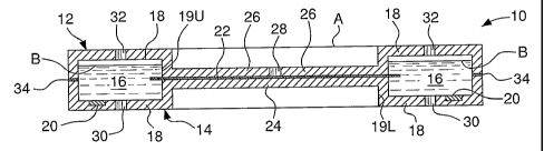
electrophoresis has been simplified considerably through the use of
commercially available pre-cast gels. Prior to this, gels were manufactured as
needed in the test labs. Since gels are typically very fragile, it is
necessary to
protect the gels during shipment from the manufacturer to the test lab, as
well as
while in storage. Many of the commercially available pre-cast gels are sold
sandwiched between rigid protective plastic or glass plates, while some merely
have a flexible plastic backing and are stored within vacuum-sealed bags.
There
are also some manufacturers who supply gels in cassettes. In the field of gel
electrophoresis, the term "cassette" generally refers to a rigid structure
that has a
gel located within it. Such cassettes not only operate to protect the gel, but
also
provide a convenient mechanism for transporting the gel prior to, during and
after the electrophoresis process.
[0004] The steps described above for conducting the electrophoresis
process can be performed in either the vertical or horizontal direction. In
vertical gel electrophoresis, the gel is typically placed within a cassette
that is
open at both ends. Each end is in fluid communication with a different well
containing a buffer. One well is typically located above the cassette and the
other below. The cassette frequently serves at least as part of one wall of
the
upper buffer well. The cassettes that are typically used in vertical
electrophoresis processes contain only the gel (i.e., no buffers or
electrodes).
Thus, separate wells are necessary in the vertical gel electrophoresis to
provide
the source for the buffer and the electrodes for providing the voltage. U.S.
Patent Nos. 5,736,022 and 6,027,628 describe conventional cassettes for use in
vertical gel electrophoresis.
[0005] Heat dissipation is a major problem during gel electrophoresis.
As the electric current passes through the gel, the buffer and gel begin to
heat
up. As the heat increases, it has a deleterious effect on the gel. If the heat
is not
dissipated, the gel will begin to breakdown. Accordingly, much effort has been
CA 02498362 2005-03-09
WO 2004/025252 PCT/US2003/028448
-3-
expended in recent years to develop cooling systems that dissipate the heat
generated during the process.
[0006] U.S. Patent No. 5,888,369 describes the incorporation of an
external heat exchanger in a vertical gel electrophoresis apparatus for
circulation
and cooling of the buffer. The apparatus accommodates cassettes that function
to separate the two buffer wells. Ports are formed in one of the buffer well
walls
for channeling the buffer to the heat exchanger for cooling.
[0007] In horizontal gel electrophoresis, the gel is oriented
predominantly in the horizontal direction. There are two general types of
horizontal gel electrophoresis arrangements. In the first arrangement, the gel
is
placed on a slab above the two buffer wells. Each end of the gel is in contact
with a porous wick that has an end located within the buffer in a buffer well.
The wick conveys a sufficient amount of buffer and electrical current from the
buffer well up to the gel. In the second arrangement, the gel is submerged
under
a thin layer of buffer, which extends from one well to the other. This is
typically called "submarine" gel electrophoresis since the gel is at least
partially
submerged.
[0008] U.S. Patent Application Publication No. 20010037940 describes
a conventional cassette for use in a horizontal gel electrophoresis apparatus.
The cassette again serves to separate the two buffer wells of the apparatus.
This
is essentially, a horizontal adaptation of the typical vertical apparatus. The
cassette includes a gel that extends into two reservoirs internal to the
cassette
(which are initially empty). The two reservoirs are located on opposite sides
of
the gel. When the cassette is inserted into the horizontal gel electrophoresis
apparatus, each cassette reservoir communicates through side openings with one
of the buffer wells in the apparatus. The apparatus buffer wells contain the
electrodes for supplying the voltage. As such, when the apparatus buffer wells
are filled with buffer, the buffer flows into the cassette reservoirs through
the
side openings and contacts each end of the gel. After each electrophoresis
process is run, the apparatus buffer wells are emptied manually and the
cassette
is then removed. The cassette's reservoirs must be separately emptied.
CA 02498362 2005-03-09
WO 2004/025252 PCT/US2003/028448
-4-
[0009] While gel electrophoresis has become ubiquitous in the
molecular biology laboratory, it has remained a laborious and time-consuming
process that has largely resisted automation because of the need for human
intervention at various stages. These include not only filling and emptying
the
buffer wells, but also removing the gel, blotting the separated molecular
species
onto a membrane and then staining them. Some steps have been taken to
minimize or eliminate some of the labor-intensive steps. For example, U.S.
Patent Nos. 3,715,295, 3,865,712, 5,582,702 and 5,865,974 describe self-
contained cassettes that include a pre-cast gel, electrodes and buffer. These
cassettes only require connection to a voltage source for operation. Such self-
contained cassettes are sold by Invitrogen Corporation (Carlsbad, CA) under
the
E-Gel" trademark. By their very nature, such self-contained cassettes use
small
amounts of buffer and carry low currents when in operation, thus eliminating
the
need for a dedicated cooling system.
[0010] Two-dimensional ("2D") gel electrophoresis is an extremely
powerful separation tool that is becoming an increasingly important first step
in
proteomic analysis. 2D gel electrophoresis typically involves: (1) a "first
dimension" separation according to isoelectric point in a,pH gradient gel, (2)
transfer of the separated molecular species to a second gel, and (3) a "second
dimension" separation according to molecular size along a direction
perpendicular to that of the first separation. The need to use two different
gels,
and the complexity and variability of the transfer between them, make
automation of 2D gel electrophoresis an even greater challenge than that of 1D
gel electrophoresis.
[0011] One system for 2D separation is discussed in U.S. Patent No.
4,443,319. The system disclosed in that patent uses a cassette that includes
both
the gel and the electrodes, and which is open for the admission of buffer.
Provisions are made for a second gel and a second set of electrodes to be used
when the cassette is used in a 2D gel electrophoresis. However, the steps
involved in the disclosed system are rather cumbersome and must be performed
manually.
CA 02498362 2005-03-09
WO 2004/025252 PCT/US2003/028448
-5-
[0012] Haber has developed a revolutionary electrophoresis technique
(hereinafter referred to as the "Haber technique") that allows separations to
be
performed in as little as five minutes. U.S. Patent Nos. 3,984,298 and
4,146,454
describe the Haber technique. In addition to the short cycle time, the Haber
technique utilizes low amounts of current and a small volume of buffer.
Specifically, the Haber technique uses less than one milliliter of buffer in
each
well and is operated with currents below 0.5 mA. As such, there is no need for
a
cooling system. The buffers used with this technique contain conductivity
suppressants. Accordingly, most of the current is carried by the molecular
species being separated, rather than by ions in the buffer as in conventional
gel
electrophoresis. The sample is placed near the middle of the separation
substrate (hereinafter referred to simply as the "substrate"). When the
current is
applied, some molecular species migrate toward the anode while others migrate
toward the cathode. This technique is also described in N. Haber, Proc. Natl.
Acad. Sci., 79, 272 (1982) and in N. Haber, Biotechnology & Histochemistry,
73, 59 (1998). An apparatus using this technique is sold by Haber Inc.
(Bayonne, NJ).
[0013] Unfortunately, the Haber technique has received little attention,
perhaps because of the dearth of suitable substrates. Although Haber has used
gels, cellulose and other substrate materials, most of his reported work used
filter paper. The primary deficiency of filter paper is that the resulting
resolution is limited by broadening from diffusion that takes place in the
absence of an applied electric field.
[0014] A need therefore exists for a method, apparatus and cassette
suitable for automated high-throughput electrophoretic separations on solid
substrates that can take advantage of techniques that use small buffer
volumes.
Summary of the Invention
[0015] The present invention relates to a method for performing
electrophoretic separations on a solid substrate. The method includes the
automated supplying and removal of buffer or other liquids to/from a
separation
chamber or cassette, as well as the controlled application of electrical
voltages.
CA 02498362 2005-03-09
WO 2004/025252 PCT/US2003/028448
-6-
The automated procedure eliminates or reduces the need for human intervention
once the separation protocol is selected and the process initiated.
[0016] It is contemplated that the process may optionally involve, after
separation, contacting the substrate while still inside the cassette with one
or
more liquids for chemical or other treatment of the separated molecular
species,
such as dye staining; radio-, immuno- or other labeling; or enzymatic
digestion.
In one preferred embodiment, after each separation, the interior of the
cassette is
rinsed and dried with the substrate still inside in order to facilitate
subsequent
handling of the substrate and/or examination of the separation results.
[0017] The separation chamber of the invention is hereinafter referred to
as a "cassette" irrespective of whether it is easily inserted into and removed
from the apparatus. A cassette with a substrate located within it is
hereinafter
referred to as a " loaded cassette". The cassette of the invention includes at
least
one pair of reservoirs for holding buffer (hereinafter referred to as "buffer
reservoirs"), each reservoir containing an electrode and each in contact with
a
section of the substrate (when loaded). The substrate is placed substantially
between each pair of buffer reservoirs and in fluid communication with all
buffer reservoirs. At least one external port connects each reservoir to
liquid
supply and waste containers. At least one external port is connected to each
reservoir for venting air, either directly outside or to a gas recovery
container,
and/or for connecting each reservoir to a pressurization/depressurization
system
and/or a liquid waste container. At least one external electrical contact is
connected to each electrode and used to connect to a voltage supply.
[0018] For 2D electrophoresis, the cassette of the invention includes a
second set of reservoirs and electrodes positioned orthogonal to the first
set.
The second pair of electrodes is designed to generate an electric field
perpendicular to that generated by the first pair. The electrodes are
connected so
that, at any one time, voltage may be applied to one pair of electrodes and
not to
the other.
[0019] The cassette of the present invention preferably includes an
additional reservoir (hereinafter referred to as the "substrate reservoir")
located
between the two buffer reservoirs for 1D cassettes and between both pairs of
CA 02498362 2005-03-09
WO 2004/025252 PCT/US2003/028448
-7-
buffer reservoirs for 2D cassettes, and separate from them. The substrate
reservoir encloses most of the substrate and serves to rapidly saturate the
substrate with buffer, dye solution and other liquids, or with gases.
[0020] The substrate may be loaded into the cassette with the sample
already on it, or the cassette may have at least one opening (hereinafter
referred
to as a "sample port") on one of its faces through which the sample(s) is/are
placed on the pre-loaded substrate. The cassette is preferably designed to be
opened after separation to permit removal of the substrate and examination of
the separation results. The empty cassette may be later reloaded with a fresh
substrate and reused. Alternatively, at least part of one cassette face is
transparent to permit examination of the separation results without having to
open the cassette and remove the substrate, in which case the cassette may
later
be discarded with the substrate in it. The environmental advantage of the
disposable cassette of the invention over those of the prior art is that the
cassette
of the invention can be made free of buffers or other chemicals when
discarded.
[0021] Preferably, the cassette of the invention is easily inserted into and
removable from ("docking" and "undocking") the apparatus in which the
separation is conducted. In this case, the cassette includes fluid ports and
electrical contacts, which readily connect to the corresponding fluid ports
and
electrical contacts on the apparatus. Such quick-connect systems are commonly
used in a wide variety of liquid delivery, electrical and electronics
applications.
The substrate may thus be loaded into the cassette in advance and unloaded
subsequently (or the cassette may be discarded) without tying up the
apparatus.
[0022] Any suitable substrate may be used with the present invention.
including filter paper, nitrocellulose membranes and gels, such as those
described in U.S. Patent Nos. 3,984,298 and 4,146,454. In addition, various
gels, preferably attached to plastic or other rigid or flexible backing are
suitable
for use with the present invention according to conventional gel
electrophoresis
techniques.
[0023] Various methods are also described herein for use with the
different cassette embodiments disclosed. One method embodiment uses a
CA 02498362 2005-03-09
WO 2004/025252 PCT/US2003/028448
-8-
continuously moving substrate roll or fan-fold passing through a pre-docked
cassette.
[0024] For automated high-throughput separations, the method,
apparatus and cassette of the invention are most advantageously combined with
standard automated laboratory systems such as robotic stacking = and conveying
systems for cassette or substrate storage and supply, robotic pipettes for
automated sample placement on substrates, and automatic separation scanning,
digitizing, storing and processing systems for examination of the separation
results.
[0025] The method, apparatus and cassette of the invention are most
effective for separations requiring only small volumes of buffer. For example,
three hundred 2D separations using the Haber technique as it is applied to the
present invention (notably including dye staining) can be performed
automatically, without human intervention once the process has been initiated,
in less than one hour and consuming less than two litters of each buffer.
[0026] The foregoing and other features and advantages of the present
invention will become more apparent in light of the following detailed
description of the preferred embodiments thereof, as illustrated in the
accompanying figures. As will be realized, the invention is capable of
modifications in various respects, all without departing from the scope of the
invention. Accordingly, the drawings and the description are to be regarded as
illustrative in nature, and not as restrictive.
Brief Description of the Figures
[0027] For the purpose of illustrating the invention, the drawings show a
form of the invention which is presently preferred. However, it should be
understood that this invention is not limited to the precise arrangements and
instrumentalities shown in the drawings.
[0028] Figure 1 illustrates exploded isometric views of 1D and 2D
embodiments of a generic cassette according to the present invention;
CA 02498362 2005-03-09
WO 2004/025252 PCT/US2003/028448
-9-
[0029] Figures IA-1D illustrate various cross-sections of the cassettes of
Figure 1 according to different embodiments of the present invention;
[0030] Figures 2A-2D illustrate additional cross-sectional variations of
the cassettes of Figure 1 according to alternate embodiments of the present
invention;
[0031] Figure 3 is a top view of an open 2D cassette according to the
embodiment shown in Fig. 2D;
[0032] Figure 4 illustrates additional cross-sectional variations of the
cassette shown in Fig. 2D according to alternate embodiments of the present
invention;
[0033] Figure 5 is a top view of the body of a 2D cassette according to
the modified embodiment of Fig. 4C;
[0034] Figure 6 is a schematic representation of liquid and gas manifold
systems for use in an apparatus according to the present invention;
[0035] Figure 7 is a schematic representation of a 2D cassette using a
continuously moving roll or fan-fold substrate; and
[0036] Figure 8 is a schematic representation of an apparatus according
to the present invention.
Detailed Description of the Various Embodiments
[0037] The present invention pertains to a method, apparatus and
cassette for performing automated electrophoretic separations on solid
substrates, based primarily on the supply and removal of buffers and other
liquids, and of electrical voltages, to and from a separation chamber
(cassette),
all without the need for human intervention once the separation protocol is
selected and the process is initiated. Unless otherwise specified, the term
"substrate" as used in this application is intended to encompass not only the
substrate itself, but any backing or frame onto which the substrate may be
CA 02498362 2005-03-09
WO 2004/025252 PCT/US2003/028448
-10-
disposed. Additionally, reference to a sample placed on a substrate is
intended
to include multiple samples placed on the same substrate.
[0038] The cassette of the invention is made largely from materials that
are both electrically non-conducting and chemically resistant to the buffers
used.
For use with the Haber technique, the preferred materials include
polytetrafluoroethylene ("PTFE", which is marketed by the DuPont Company
under the trademark Teflona), PVDF (commonly used in corrosion-resistant
pipes and tubing), nylon, glass, or ceramic. Other materials may be used in
the
present invention, provided that any surface exposed to the buffers includes a
coating of rugged, continuous, impermeable cladding of a chemically-resistant
and electrically-insulating material such as PTFE, PVDF, glass or ceramic.
Components that serve primarily for heat dissipation are advantageously made
from glass-, ceramic- or PTFE-clad aluminum. For use with conventional gel
electrophoresis techniques, the cassette can also be made from other materials
commonly used with those techniques.
[0039] The substrate may be a gel of any type used in conventional gel
electrophoresis. Alternatively, the substrate can be filter paper or any of
the
other substrate described in Haber. The substrates used in the Haber technique
have the advantages of speed, low heat generation and low buffer usage. In
order to facilitate handling, especially with an automated high-throughput
operation as described below, the substrate is preferably attached to a
backing or
frame that provides rigidity for the substrate. There are other substrates
that are
currently being developed for protein microarray applications, such as the
HydrogelTM coatings being developed by PerkinElmer Life Sciences (Boston,
MA), which may be used in the present invention.
[0040] As described below, the plane of the substrate is hereinafter
referred to as the "XY plane", the direction of the first dimension separation
is
the "X direction", the direction of the second dimension separation is the "Y
direction", and the normal to the plane of the substrate is the "Z direction".
For
simplicity, it is assumed that: (1) the cassette is shaped roughly like a
parallelepiped, with two opposing surfaces (hereinafter referred to as
"faces")
being much larger than the other four (hereinafter referred to as "edges");
and
CA 02498362 2005-03-09
WO 2004/025252 PCT/US2003/028448
-11-
(2) the faces of the cassette are parallel to the XY plane and are horizontal.
Of
course the cassette can take on a variety of different shapes and, thus, the
exemplary shape described above is not to be considered limiting in any
particular way. Similarly, the accompanying figures are intended only as
schematic representations and, since component dimensions may differ by as
much as two orders of magnitude, the figures are not drawn to scale in order
to
show some of the smaller dimensions more clearly. In addition, the figures do
not shown some features that, albeit advantageous, only serve: (1) to guide,
align or position various parts of the cassette with respect to each other;
(2) to
latch the cassette closed; or (3) to guide, align or position the cassette
relative to
the apparatus. These features, and their interaction with the cassette, would
be
readily apparent to those skilled in the art in light of the teachings
provided
herein.
[00411 The cassette of the invention docks into the electrophoresis
apparatus through two fluid manifolds, one used primarily for liquids
(hereinafter referred to as the "liquid manifold") and one used primarily for
gases (hereinafter referred to as the "gas manifold"). The two fluid manifolds
may be separate entities or may be combined in a single one. The cassette also
connects to an electrical manifold in the apparatus. The electrical manifold
may
be a separate entity or may be combined with one or both fluid manifolds into
a
single entity. The manifolds are all controlled (preferably automatically) by
the
apparatus as described in more detail below. The fluid manifolds channel
fluids
between each cassette reservoir and associated fluid sources or waste
containers
on or connected to the apparatus. It is contemplated that, in addition to
buffers
and wash solutions, the liquids that may be supplied through the manifolds
include those for treatment of the separated molecular species, such as dye
staining; radio-, immuno- or other labeling; and enzymatic digestion. While
buffers are required in the present invention, one for lD separations and two
for
2D separations, the use of additional buffers for running multiple separation
protocols on different samples, or the use of wash or dye solutions or other
post-
separation treatment liquids is optional. Since dye staining is a very common
post-separation treatment, the present specification references specifically
the
use of dye solutions and the process of dye staining. However, it should be
CA 02498362 2005-03-09
WO 2004/025252 PCT/US2003/028448
-12-
readily apparent that one or more other post-separation treatments may be
used,
instead of or in addition to, the dye staining. Furthermore, treatment may be
applied prior to or during the separation, so that it is possible to examine
the
progress of the separation while the separation progresses. For all purposes
of
this application, reference to post-separation treatment is deemed to include
any
treatment applied prior to or during the separation provided that the
appropriate
modifications in the sequence of the separation steps is made.
[0042] The first embodiment of the method of the present invention
utilizes a closed detachable cassette that has been previously loaded with a
fresh
substrate, and includes the steps of: (1) placing a sample on the substrate
through a sample port on the closed cassette and, if necessary, plugging the
sample port; (2) docking the cassette; (3) supplying and removing fluids and
voltages to and from the cassette to perform the separation and post-
separation
treatment; (4) undocking the cassette; (5) examining the separation results;
and
(6) discarding or recycling the used cassette. The used cassette may be
recycled
by unloading the used substrate and loading a fresh one. As described below,
the cassette may include a transparent window to permit viewing of the
processed substrate, although such transparent window is not necessary if the
examination of the separation results is by a non-optical method such a
radiography. Alternatively, following the separation and post-separation
treatment, the cassette may be opened and the substrate removed for
examination of the results directly, thereby eliminating the need for the
cassette
to have a transparent window for viewing the separation results.
[0043] For 2D separations, step 3 in the preceding paragraph preferably
includes the following sub-steps: (i) admitting first buffer into the first
dimension buffer reservoirs until the first buffer level is at least above the
substrate and the first dimension electrodes; (ii) waiting until the substrate
is
saturated with first buffer; (iii) applying a voltage to the first dimension
electrodes until the first dimension separation is completed, while
(preferably)
removing any first buffer that enters the second dimension buffer reservoirs
through the substrate cross-section; (iv) substantially emptying the first
dimension buffer reservoirs; (v) optionally, rinsing the first and second
dimension buffer reservoirs and the substrate with wash solution; (vi)
admitting
CA 02498362 2005-03-09
WO 2004/025252 PCT/US2003/028448
-13-
second buffer into the second dimension buffer reservoirs until the second
buffer level is at least above the substrate and the second dimension
electrodes;
(vii) waiting until the substrate is saturated with second buffer; (viii)
applying a
voltage to the second dimension electrodes until the second dimension
separation is complete, while (preferably) removing any second buffer that
enters the first dimension buffer reservoirs through the substrate cross-
section;
(ix) substantially emptying the second dimension buffer reservoirs; (x)
optionally, rinsing all the reservoirs and the substrate with wash solution;
and
(xi) optionally, drying all reservoirs and the substrate with air or other
gas.
[0044] Optionally, if post-separation treatment is desired, the following
additional sub-steps are performed between sub-steps (x) and (xi): (a)
admitting
staining dye solution or other liquid for post-separation treatment into the
first
and/or second dimension buffer reservoirs; (b) waiting until staining or other
post-separation treatment is completed; (c) substantially emptying the first
and/or second dimension buffer reservoirs; (d) optionally, rinsing the first
and/or
second dimension buffer reservoirs and the substrate with wash solution. For
1D separations, sub-steps (vi) through (xi) are omitted; any optional post-
separation treatment is performed after sub-step (v) in an analogous manner.
[0045] The above method is a preferred embodiment that may be used
with a wide variety of cassettes. One embodiment of a cassette 10 for use in
the
method is shown schematically in Fig. 1, which is an isometric view of the
cassette with its upper and lower portions shown separated. In this figure
there
is no substrate shown for clarity. Referring now to Figs. IA-1D, various cross-
sectional configurations of the cassette are shown, each showing an
alternative
configuration taken along the section line in Fig. 1. Specifically, as shown
in
Fig. 1A, the cassette 10 includes an upper portion or cover 12 and a lower
portion or body 14. The cover 12 and body 14 are designed to mate or seal
together to form an enclosure. The combination of the upper and lower portions
12, 14 defines at least two spaced apart buffer reservoirs 16. As shown, each
reservoir is formed by recessed cavities 18. While the illustrated embodiment
shows recessed cavities in both the upper and lower portions, it is
contemplated
that only one portion (either the upper or lower) may include the recessed
cavity
18.
CA 02498362 2005-03-09
WO 2004/025252 PCT/US2003/028448
-14-
[0046] At least one electrode 20 is mounted within each buffer reservoir
16. The electrode is located such that electrical current can be transmitted
into a
buffer located within the reservoir. Electrical leads (not shown) extend from
the
electrode to an electrical contact located on an external surface of the
cassette
10.
[0047] Since a 2D cassette includes additional reservoirs that are
orthogonal to the first set of buffer reservoirs, it should be readily
apparent that
a 2D cassette would look identical in cross-section to the cassette shown in
Fig.
IA.
[0048] A substrate 22 is located on a substrate support 24 formed on the
lower portion 14 between the two recessed cavities 18 in Fig. 1 A. (Of course,
in
a 2D cassette, the substrate support 24 would extend between all recessed
cavities in the lower portion 14.) A substrate cover 26 is preferably formed
in
the upper portion 12 between its associated recessed cavities 18. As will be
discussed in more detail below, the substrate cover 26 and substrate support
24
are formed on (or attached to) the upper and lower portions 12, 14 such that
the
substrate cover 26 preferably substantially contacts the upper surface of the
substrate 22 and the substrate support 24 substantially contacts the lower
surface
of the substrate 22, thereby sandwiching the substrate 22 between the two. In
order to provide proper sealing without damaging the substrate 22, the
interior
walls 19U, 19L of the recessed cavities 18 must be configured such that the
spacing formed between the interior walls 19U, 19L are spaced just enough to
contact the substrate 22 when the upper portion 12 is sealed to the lower
portion
14.
[0049] A sample port 28 is formed in the substrate cover 26 and
provides a means for placing a sample on substrate 22 without opening the
cassette 10. The location of the sample port 28 can be at any suitable
position in
the substrate cover 26, depending on the process to be run. The port in Fig.
IA
is shown centrally located which is typically associated with 2D operations
using the Haber technique (i.e., a single sample is placed roughly equidistant
from all four electrodes.) For 1D operation with the Haber technique, multiple
samples may be placed on a line parallel to the electrodes 20 and roughly
CA 02498362 2005-03-09
WO 2004/025252 PCT/US2003/028448
-15-
midway between them, in which case the cassette has multiple sample ports 28
or may have an elongated slot. For conventional 2D gel electrophoresis
techniques, the sample port 28 would be located so as to permit one sample to
be placed near one corner of the substrate for 2D separations. For
conventional
1D gel electrophoresis techniques, the sample port 28 would be located so as
to
permit multiple samples to be placed near one end of the substrate, roughly
parallel to one of electrodes 20. Of course, the cassette can be configured
without a sample port 28. However, in such cases, the substrate 22 would have
to be loaded into the cassette with a sample already on it.
[0050] As discussed above, the substrate cover 26 and support 24
preferably contact the substrate. In addition to providing sealing, the
contact
serves to dissipate heat generated during the separation. In order to permit
examination of the separation without opening the cassette, it is preferable
that
at least one of the cover 26 or support 24 include a transparent window (or be
formed from transparent material.)
[0051] The cassette 10 preferably includes fluid ports 30 which
communicate with each buffer reservoir 16. The fluid ports 30 supply and
exhaust liquids from the buffer reservoirs 16. As shown, the fluid ports 30
are
preferably formed in the bottom of the recessed cavity 18 on the lower portion
14. Although the ports 30 are shown centrally located, that is not a
requirement.
However, it is preferred that the cavities 18 be configured to facilitate flow
of
liquid to and from the ports 30 thereby providing for ease of filling and
emptying of the reservoirs 16. As will be discussed in more detail below, the
fluid ports 30 communicate with suitable supply and waste reservoirs in the
associated electrophoresis apparatus.
[0052] The cassette 10 also preferably includes vent ports 32 which
communicate with the buffer reservoirs 16. The vent ports 32 are preferably
formed as openings into the recessed cavities in the upper portion 12. The
vent
ports 32 serve to release air displaced by buffer entering reservoirs 12, any
evaporated buffer, or any gases generated during the separation. The vent
ports
32 also permit air to be readmitted into reservoirs 16 when buffer is removed.
To prevent liquid overflow through vent ports 32, a float or other one-way
shut-
CA 02498362 2005-03-09
WO 2004/025252 PCT/US2003/028448
-16-
off valve (not shown) may be incorporated into the upper portion 12. The vent
ports 32 may vent directly to ambient or, preferably, are connected through a
gas manifold to a gas recovery system. It is contemplated that pressurized air
(or other gas) may be used to facilitate removal of buffer and cleansing of
the
cassette, and depressurized air to facilitate filling. In such cases the vent
ports
30 are preferably connected through a gas manifold to a pressurization or
depressurization source.
[00531 During operation of the cassette 10 in Fig. 1A, the buffer is
channeled through fluid ports 30 into the reservoirs 16 until the buffer level
reaches a desired level (shown by dashed lines B) which is above both
substrate
22 and electrodes 20. After the separation, the buffer is exhausted through
fluid
ports 30 to a liquid waste system, while air or other gas is admitted through
vent
ports 32.
[00541 Alternatively, if one-way buffer flow is desired, either
continuously or periodically, the process would be run with the buffer
entering
the reservoirs 16 through ports 30 and exiting through vent ports 32. In this
variation of the invention, the vent ports 32 would need to connect to a
liquid
waste container. Buffer flow may also be in the opposite direction, i.e., with
the
buffer entering through ports 32 and exiting through ports 30, but this
arrangement is less desirable.
[00551 As with the fluid ports 30, the vent ports 32 can be located at any
suitable position to facilitate the electrophoresis operation, such as in the
side
walls of the upper or lower portions. Also, it may be desirable, depending on
the configuration of the apparatus, to form the vent ports 32 such that they
extend through the cassette walls or with external conduits to the bottom of
the
cassette, thus permitting supply of both liquids and gases from only one side
of
the cassette. Also, it should be readily apparent that the embodiment shown
and
described is intended for horizontal electrophoresis. However, the teachings
provided herein are also applicable to electrophoresis with the cassette
oriented
vertically or in any other inclination, provided that ports 30 and 32 are
appropriately located.
CA 02498362 2005-03-09
WO 2004/025252 PCT/US2003/028448
-17-
[0056] As shown in Fig. 1, the cassette 10 is advantageously separable
into two portions, to facilitate construction and permit convenient loading
and
unloading of substrate 22. The engagement of the portions is in a fluid-tight
manner so as to prevent leakage of buffer. Preferably a continuous compression
gasket 34, O-ring seal or other sealing device is located between the upper
and
lower portions 12, 14.
[0057] The upper portion or cover 12 may be connected to lower portion
or body 14 in any convenient manner, such as with a hinge, fasteners or it can
slide on grooves formed in the lower portion. Alternately, the upper and lower
portions can be held together by mechanical pressure from the electrophoresis
apparatus. It is also contemplated that the cassette may include a guide or
alignment portion which mates with guide or alignment portions in the
apparatus to permit proper docking of the cassette. In the cassette embodiment
shown in Fig. IA, the substrate 22 is saturated with buffer only through the
small portions of the substrate 22 that extend into the buffer reservoirs 16.
This
lengthens preparation time considerably, an important consideration when using
the Haber technique (which permits separations to be performed in each
dimension in about five minutes). Therefore, if high throughput is desired, it
is
important to accelerate as much as possible any steps prior to and subsequent
to
the separation steps themselves.
[0058] Referring now to Fig. 113, a second embodiment of the cassette
is shown. In this embodiment, the buffers reservoirs 16 are not separated.
Instead, buffer is permitted to flow between the buffers over the top of the
substrate. In this configuration, the interior walls 19U, 19L are sized so
that a
gap remains between the upper portion and the lower portion when they are
sealed to one another. Thus, in use, the substrate 22 will be covered with a
layer
of buffer in a manner analogous to conventional submarine gel electrophoresis.
The additional buffer increases the rate of diffusion into substrate 10.
However,
the additional buffer results in increased current passing through the layer
of
buffer above the substrate 22. The increased current contributes to the
generation of heat during the process without furthering the separation
process.
This increased current is referred to herein as "unproductive current." In
order
to minimize the unproductive current (and, thus, minimize the unwanted
CA 02498362 2005-03-09
WO 2004/025252 PCT/US2003/028448
-18-
development of unnecessary heat), it is desirable to make the buffer layer
over
the substrate as thin as possible. Furthermore, in this embodiment, sample
port
28 serves to prevent air from becoming trapped under the substrate cover 26.
[0059] Referring now to Fig. 1 C, an embodiment of the invention is
shown which includes a porous layer 35, such as filter paper or sponge
material,
which is located between the substrate 22 and the substrate support 24.
Alternatively, the porous layer 35 may be placed between the substrate 22 and
substrate cover 26, or on both sides of substrate 22. The porous layer 35
serves
to facilitate the flow of buffer into the substrate 22.
[0060] Referring now to Fig. 1D, a fourth cassette embodiment is
shown. In this embodiment, the substrate 22 is larger and extends into and
bends downward into the reservoirs 16. The ends of the substrate 22 are
preferably secured at the bottom of buffer reservoirs 12 by ledges 36 or some
other means. To ensure that buffer is not trapped behind ledges 36 and behind
substrate 22 (where the latter meets the bottom of buffer reservoirs 12), both
ledges 36 and substrate 22 have substantial openings that allow buffer to
escape.
In this cassette embodiment, the buffer is first admitted up to the level
shown by
the dashed lines identified by the letter B to allow it to form a layer of
buffer
over the substrate 22. At this point, the buffer reservoirs 16 (as well as the
second dimension buffer reservoirs) are fluidly connected. After substrate 22
is
saturated with buffer, the buffer level is lowered to the level shown by
dashed
lines identified by the letter C and then the separation process is initiated.
[0061] When using the embodiment of the cassette shown in Fig. 1D,
the method described above is modified by adding the sub-steps (in both the 1D
and 2D versions) of lowering the first buffer level to below the horizontal
separation area of the substrate so that a sufficient amount of substrate is
located
within the buffer to permit electric current to flow from the buffer into the
substrate.
[0062] It is also contemplated that, when using the embodiment of the
cassette shown in Fig. 1D, the buffer may be admitted through sample port 28
and runs over substrate 22 down into the buffer reservoirs 16 until the buffer
CA 02498362 2005-03-09
WO 2004/025252 PCT/US2003/028448
-19-
level is at the level shown by dashed lines C, and the separation proceeds
with
the buffer at that level.
[0063] Referring now to Fig. 2A, a preferred embodiment of the cassette
is shown. In this embodiment the entire periphery of substrate cover 26 is
attached to the upper portion 12 through a fluid-tight hinge 38, which allows
movement up and down of the substrate cover 26. During operation when no
voltage is applied, the substrate cover 26 is generally located up and away
from
substrate 22. The buffer is then introduced, flowing across the top of the
substrate 22 rapidly saturating the substrate 22. After saturation, the
substrate
cover 26 is located against the substrate 22, thus functioning as a heat sink
while, at the same time, forcing any excess buffer from the top of the
substrate
22. The hinge 38 preferably biases the substrate cover 26 away from the
substrate 22. The substrate cover 26 is urged down against the substrate 22 by
the apparatus when the voltage is applied. The substrate support 24 can
likewise
(or alternately) be attached to the lower portion through a hinge such that
the
support can be controlled to move toward and away from the substrate. The
same result may be obtained by replacing the hinge with a gasket that provides
a
compression or sliding seal, in a manner similar to that described below.
[0064] Fig. 2B illustrates a variation on the hinge embodiment described
above. In this embodiment, the upper and lower portions 12, 14 are movable
with respect to one another. This can be achieved by incorporating a
compression seal 40, such as a high-compliance tube gasket (0-ring) or V-
gasket, in place of the seal described previously. The flexibility of the seal
permits variation in the spacing between the upper and lower portions while
maintaining a fluid-tight seal. Thus, as in the embodiment shown in Figure 2A,
the initial spacing of the upper and lower portions 12, 14 is such that a
layer of
buffer is permitted to form over the substrate 22 to increase the speed of
saturation. After saturation in complete, the upper and lower portions 12, 14
are
compressed toward one another thereby eliminating the buffer on top of the
substrate 22. Similar results can be achieved with the preferred arrangement
shown in Fig. 2C where a sliding seal is incorporated between the upper and
lower portions 12, 14. The sliding seal includes an O-ring gasket 42, with
optional springs 44 to bias the upper portion 12 away from the lower portion
14.
CA 02498362 2005-03-09
WO 2004/025252 PCT/US2003/028448
-20-
[0065] In the cassette embodiments shown in Figs. 2A-2C, when those
cassettes are configured for 2D separation (i.e., four buffer reservoirs),
after the
substrate 22 has been saturated with buffer and buffer layer above the
substrate
has been eliminated, buffer will still remain in all the buffer reservoirs 16,
including the' non-operating reservoirs. The buffer in the non-operating
reservoirs can provide a path for unproductive current and thus increase heat
dissipation. In order to minimize unproductive current and decrease the amount
of heat dissipated, the non-operating buffer reservoirs are preferably emptied
before voltage is applied for each separation. For example, when conducting
the
first dimension separation, the second dimension buffer reservoirs are emptied
before voltage is applied. The buffer that is removed can be channeled to the
appropriate buffer reservoirs 16 through the liquid manifold on the apparatus.
A
similar operation is undertaken before beginning the second dimension
separation.
[0066] Referring now to Fig. 2D, another preferred embodiment of the
cassette is shown which incorporates an additional reservoir 46 (hereinafter
referred to as the "substrate reservoir") located above or below the central
portion of the substrate 22. The substrate reservoir 46 conununicates with the
fluid manifolds through its own supply/exhaust and vent ports (not shown in
the
cross-sectional plane). The sample port 28 may also serve as the vent port for
the substrate reservoir 46, or it may be plugged after a sample has been
placed
on the substrate 22.
[0067] The substrate reservoir 46 may be filled with the first buffer
before, at the same time as or after the buffer reservoirs 16 are filled.
Because
of the large exposed surface of the substrate 22 within the substrate
reservoir 46,
the substrate 22 rapidly saturates. In addition to supplying the buffer to the
substrate 22, the substrate reservoir 46 may also be advantageously used for
saturating the substrate 22 with dye solution, rinsing off excess dye, and
drying
the substrate 22 prior to its removal or prior to examination of the
separation
results. In order to minimize unproductive current, the substrate reservoir 46
is
preferably emptied prior to voltage application. In order to conserve buffer,
the
buffer can be channeled to the appropriate buffer reservoirs 16 through the
liquid manifold on the apparatus, or internally through the cassette, rather
than
CA 02498362 2005-03-09
WO 2004/025252 PCT/US2003/028448
-21-
being discarded. Alternatively, the volume of buffer admitted into the
substrate
reservoir 46 can be limited to an amount sufficient to saturate substrate 22,
with
substantially no excess buffer left over.
[0068] When empty, substrate reservoir 46 provides poor thermal
contact between the substrate 22 and the substrate cover 26. As such, this
embodiment of the cassette relies primarily on the substrate support 24 for
heat
dissipation. In order to alleviate this deficiency an electrically insulating
liquid
may be introduced into the substrate reservoir 46 during voltage application.
Such liquids are commonly used in high voltage transformer applications. The
liquid should be selected so as to have a sufficient enough viscosity to
prevent
diffusion into the substrate 22.
[0069] While the two-part arrangement for the cassettes shown in
Figures 1, lA-1D and 2A-2D above is preferred, other practical arrangements
are possible. For example, Figure 3 is a top view of the body 14 of a 2D
cassette according to the embodiment of the invention shown in Fig. 2D, with
the substrate 22 shown in phantom but with the gasket 34 in place. As
discussed
above, this embodiment of the invention permits all liquid feeding and
draining
to occur from the bottom of the cassette. The first and second dimension
buffer
reservoirs 16 and the substrate reservoir 46 are shown with supply/exhaust
ports
30 for the buffer reservoirs. Also shown is a preferred location for the
supply/exhaust port 48 for the substrate reservoir 46. The substrate
preferably
has an opening formed in it to permit the fluid flow to and from the substrate
reservoir 46 through the exhaust port 48 below. The electrodes 20 extend into
the recessed cavities in the body 14 with the electrical connectivity being
provided through the bottom wall of the body 14. Preferably, electrical
contacts
are formed on the bottom, outer surface of the cassette which are designed to
align with and contact, when the cassette is docked, corresponding electrodes
in
the electrical manifold, which in turn connect to a power source in the
apparatus. The electrodes 20 can be positioned anywhere inside the respective
buffer reservoirs as long as they are covered with buffer during the
separation.
A 1D cassette would be similar to that shown except that the second set of
buffer reservoirs 16 and associated electrodes 20 would be eliminated.
CA 02498362 2005-03-09
WO 2004/025252 -22- PCT/US2003/028448
[0070] It is contemplated that the substrate 22 may be cross-shaped, with
one branch extending into each buffer reservoir 16, irrespective of the shape
of
any backing to which it may be affixed (e.g., a cross-shaped substrate
attached
to a square backing). Alternatively, if the substrate 22 covers the entire
surface
of body 14, the gasket 34 is not needed if the substrate 22 can be compressed
at
the periphery to provide a fluid-tight seal.
[0071] The size and shape of the cassette can be changed as needed
depending on the volume of buffer needed. For example, the face dimensions of
the cassette can be decreased by reducing the footprint of the buffer
reservoirs
and increasing their height. For example, for an 8 cm x 8 cm substrate
reservoir
and 4 cm x 8 cm buffer reservoirs, the cassette face minimum dimensions are 16
cm x 16 cm. By decreasing the buffer reservoir footprint to 1 cm x 8 cm (and
increasing reservoir height from 1 mm to 4 min) the minimum cassette face
dimensions are reduced to 10 cm x 10 cm. Alternatively, if a continuous flow
of buffer is provided, both the footprint and the height of the buffer
reservoirs
can be reduced to a just one or two millimeters.
[0072] Although the cassette embodiments shown in Figs. lA-1D and
2A-2D illustrate the buffer reservoirs 16 extending both above and below the
substrate 22, it is also contemplated that in applications where it is
important to
minimize the buffer volumes used (e.g., the Haber technique for large numbers
of separations), the reservoir spaces below the substrate 22 may be
eliminated.
Referring to Figs. 4A-4C, variations on the embodiment of the cassette
illustrated in Fig. 2D are shown which eliminate the recessed cavity in the
body
14. Those skilled in the art would be readily capable of making similar
changes
to the other cassette embodiments (other than the embodiment of Fig. 1D) in
light of the teachings herein.
[0073] Fig. 4A shows the cassette of Fig. 2D modified such that all the
reservoirs are at or above the level of the substrate 22 in order to minimize
the
buffer volume used. Also, the venting is redirected to the bottom face of the
cassette in order to allow gas recovery as well as pressurization of the
reservoirs
from one side only, thus permitting the cassette to be used in a simpler
docking
configuration. With the cover 12 raised, the substrate 10 is free to move on
the
CA 02498362 2005-03-09
WO 2004/025252 PCT/US2003/028448
- 23 -
top surface of body 14, thus facilitating automated loading. Since both
supply/exhaust and vent ports now are all located on the body 14, they are not
visible in Fig. 4A, but are illustrated in Fig. 5.
[0074] Fig. 4A also illustrates how the cover 12 can be conveniently
fabricated using three compressible sheet gaskets 50, 52 and 54, which are
preferably held by friction inside cover 12. Since they only need to be a few
millimeters high, reservoirs 16 and 46 can be formed by cut-outs in a single
sheet gasket 54, with walls 56 (which join out of the plane of the figure)
separating them. While one gasket 54 is shown, it is also contemplated that
multiple gaskets can be used to form the necessary reservoir height. In order
to
permit venting through the bottom, gasket 50 has horizontal cut-out channels
proximal to the vent opening in each reservoir which extend downward,
traversing gaskets 52 and 54 and the body 14, and terminating on the bottom
face of the cassette. None of the cut-outs in gasket 50 are shown in Fig. 4A
since they are out of the plane of the cross-section. They are, however,
described in more detail with respect to Fig. 5. Alternatively, gasket 50, or
all
three gaskets 50, 52 and 54, is/are combined with cover 12 into a single
molded
piece of material or are otherwise formed from one piece of material.
[0075] Gasket 54, with a single large central cut-out section, serves three
principal functions: (1) to compensate for the thickness of substrate 10 and
permit gasket 52 to seal in a fluid-tight mamier to the substrate 22 and the
base
14, (2) to match the contour of the substrate 22 between reservoirs with no
gaps
connecting reservoirs, and (3) to assist in maintaining the position of the
substrate 22 in the XY plane. The fit between the gasket 54 central cut-out
and
the substrate 22 is sufficiently loose for substrate 22 to be easily inserted,
and
the small gap between the two is sealed through compression of gasket 54 when
the cassette is closed. Gasket 54 is not needed for thin substrates since
gasket
52 can be compressed slightly more over substrate 22 than elsewhere. For much
thicker substrates 22 or for substrates on backing or frames, compression of
gasket 52 may not be sufficient to overcome the height of the substrate 22,
and
gasket 54 would then be necessary. Body 14 and cover 12 are sealed to one
another by outer gasket 34, which is optionally an integral part of one of
gaskets
50, 52 or 56. The height of cover 12 and the thickness of gasket 34 are
CA 02498362 2005-03-09
WO 2004/025252 PCT/US2003/028448
-24-
configured such that, upon closure of the cassette, gaskets 52 and 54 are not
compressed beyond what is needed to separate reservoirs 16 and 46.
[0076] A heat sink 60 may be included on the lower, external surface of
the base 12, preferably under the substrate support 24. The heat sink 60 is
preferably made from aluminum or similar material with high thermal
conductivity. Cooling fins 62 may be added for increased heat transfer.
Preferably, the substrate support 24 is formed as a very thin electrically
insulating barrier for increased heat transfer. The bottom surface of the
substrate support 24 may be coated with a high thermal conductivity paste to
facilitate heat transfer to the heat sink 60. Alternatively, the substrate
support
24 may be formed integral with the heat sink 60. In order to increase cooling,
a
fan or blower may be incorporated into the apparatus or cassette. It is also
contemplated that, instead of a finned heat sink, the heat sink could be a
thermoelectric cooling unit mounted in the apparatus or cassette. Another
variation that is possible for the heat sink is the replacement of the cooling
fins
62 with a cooling jacket within the heat sink 60 through which an externally
cooled liquid is circulated. With some modifications of the arrangement shown,
the cooling liquid may be buffer which is circulated from one of the buffer
reservoirs 16. How much heat needs to be dissipated depends on the separation
process being used. For example, a separation using the Haber technique
typically generates on the order of 3 watts, which is low compared to other
processes but is not negligible.
[0077] Figure 4B shows a modification of the embodiment in Figure 4A.
In this embodiment, the bottom peripheral section 64 of the cover 12, where
the
substrate 22 and gaskets 52 and 54 are located, is detachable from the rest of
the
cover 66. The entire detached section (including the cover side portion 64,
substrate 22 and gaskets 52 and 54) is free to move on the top surface of body
14, thus facilitating automated substrate loading.
[0078] Referring now to Figure 4C, an additional modification is shown
wherein the substrate support 24 and the heat sink 60 are detachable. As such,
the opening thus formed permits a substrate to be inserted into the cassette
and
CA 02498362 2005-03-09
WO 2004/025252 PCT/US2003/028448
-25-
then the removed section placed back in. A seal 68, such as a compression
gasket, is inserted between the substrate support 24 and the base 14.
[0079] The configuration of Fig. 4C also lends itself to modification of
the embodiment shown in Figs. 2B and 2C by the replacement of the seal with a
high-compliance compression gasket (Fig 2B), or a sliding seal (Fig. 2C), and
the elimination of the central cut-out for substrate reservoir 16.
[0080] With respect to Figures 4A-4C, it is readily apparent that the
electrodes 20 may, alternatively, be affixed to the substrate 22, or to its
backing
or frame, instead of being on the body 14. Or the electrodes 20 may be
alternatively incorporated into the cover 12.
[0081] With respect to all of the cassette embodiments described above,
particularly as shown in Figures 1, 1A-1D, 2A-2D and 4A-4C, it is assumed
above, for simplicity, that the cassette separates into two pieces, a body and
a
cover, between which the substrate is placed. While such an arrangement is
preferred because it has many practical benefits, particularly ease of
construction of the cassette and ease of loading and unloading the substrate,
other arrangements are also practical if less advantageous. Referring to
Figure
2D, for example, a 1D cassette is readily constructed in three parts: the left
reservoir 16 excluding its right wall, the central section accommodating the
substrate and including the right wall of the left reservoir 16 and the left
wall of
the right reservoir 16, and the right reservoir 16 excluding its left wall.
[0082] Referring now to Figure 5, a top view of the body 14 of a 2D
cassette according to Fig. 4C is shown. In the illustrated embodiment, the
gasket 34 around the periphery and the detachable substrate support 24 and the
heat sink 60 are removed, showing the opening defined by edges 70. The
outlines of the buffer reservoirs 16 and the substrate reservoir 46, defined
by the
gasket 52 above, are shown for reference as phantom lines. For the substrate
22
to be loaded and unloaded without disturbing either the attachment of the body
14 to the cover 12 or the docking of the body 14 into the apparatus, all fluid
ports and electrical contacts are channeled to locations outside the
detachable
section.
CA 02498362 2005-03-09
WO 2004/025252 PCT/US2003/028448
-26-
[0083] In addition, in order to facilitate loading the substrate 22 along
the Y (lateral) direction, none of the connections with the apparatus are
located
either in front of or behind the detachable section. Thus, relative to Fig. 3,
the
supply/exhaust ports 30, 48 are redirected to the side, using channels 72, 74
formed in the gasket 52 (essentially extensions of the reservoirs). All the
supply/exhaust ports traverse the body 14 downward to end on the bottom face
of the cassette. In order to channel the vent ports to the bottom, horizontal
channels 76, 78 and 80 are cut into gasket 50 above, connect to vent ports 82,
84
and 86 traversing gaskets 52 and 54 and the body 14. In addition, the
locations
of the contact areas are to the sides of the cut-out region, thus requiring
the
electrical connections to the electrodes 20 to be routed appropriately.
[0084] As shown in Fig. 5, each one of the channels leads to a different
vent port 82, 84 or 86 on the bottom face of the cassette. Alternatively, the
channels can be formed so as to converge to a single conduit which extends to
one vent port on the bottom face of the cassette. This alternative is less
forgiving of minor overfilling of reservoirs since they now communicate with
one another through gasket 50 above.
[0085] As illustrated in the accompanying figures, the buffer reservoirs
in each pair are not designed to communicate directly with one another. There
are two principal reasons for this. First, it is sometimes desirable to have a
different buffer in each of the buffer reservoirs 16 in each pair in order for
the
separation to take place in a buffer gradient (e.g., a pH gradient if each
buffer
has a different pH). Second, a buffer-filled channel connecting the buffer
reservoirs 16 in each pair provides a path for unproductive current and adds
to
the need to dissipate heat. If the buffer reservoirs 16 in each pair connect
only
through the liquid manifold, the path is not only longer but is also
interrupted
during voltage application by two closed electrically-insulating valves. If
heat
dissipation and current handling capacity are not an issue, then the cassette
and
the liquid manifold can both be made simpler by connecting the supply/exhaust
openings of both buffer reservoirs 16 in each pair inside the cassette.
[0086] Because of their substantially closed nature, the cassettes of the
present invention can be operated vertically or with any other inclination
CA 02498362 2005-03-09
WO 2004/025252 PCT/US2003/028448
-27-
provided that the arrangement of fluid ports is modified appropriately. For
each
reservoir, the supply/exhaust opening is preferably near the reservoir's
lowest
point so that substantially no liquid remains when the reservoir is emptied,
while
the vent opening is preferably near the highest point so that substantially no
air
is trapped when the reservoir is filled. Therefore, the inclination with which
the
cassette is to be operated dictates the location of the fluid openings for
each
reservoir. For horizontal operation, the fluid opening arrangement is not
critical
since all venting occurs above the top of all reservoirs. However, if the
reservoirs are just a few millimeters high then even a relatively small
unintended
cassette inclination may have a significant effect. An easy solution is to
purposely incline the cassette enough to ensure that the supply/exhaust and
vent
openings are always near each reservoir's highest and lowest points,
respectively, even if the apparatus is not closely leveled. Preferably the
inclination should be greater than ten degrees.
[0087] In addition to being operable horizontally, the 2D cassette of Fig.
meets all the requirements for operation with the edge at the top of the
figure
higher than the edge at the bottom of the figure (e.g., vertically). This is
made
possible by the upward direction of channels 76, 78 and 80, as shown, which
permits complete filling of all reservoirs with the cassette oriented
vertically.
Alternatively, vent channels 76, 78 and 80 may all be directed, in a similar
manner, to the same edge of the cassette for edge docking instead of face
docking.
[00881 It is also contemplated that the method disclosed above may be
practiced with a cassette that does not have the cover attached except while
in
operation, thus eliminating the need for openings for sample introduction or
transparent faces for examination of the separation results.
[00891 Furthermore, the present invention may be practiced with a
cassette that is docked but does not include a substrate (e.g., using the
cassettes
of Figs. 4A-C). As such, the disclosed method would be modified to
incorporate the steps of loading and unloading the substrate into and out of
the
cassette. It is not necessary for the cassette used in this embodiment to be
easily
detachable from the apparatus, except that it preferably is so as not to
inhibit
CA 02498362 2005-03-09
WO 2004/025252 PCT/US2003/028448
-28-
apparatus maintenance. Unlike the first method described above, the manner in
which the substrate is loaded into the cassette is now especially important,
particularly for automated operation.
[0090] If the cassette shown in Fig. 4A is used, the method involves the
steps of (1) placing the sample on the substrate; (2) positioning the
substrate on
the body of the open cassette, with the cover raised and the body docked; (3)
lowering the cover to close the cassette in a fluid-tight manner; (4)
supplying
and removing fluids and voltages to and from the cassette to perform the
separation and post-separation treatment; (5) opening the cassette by raising
the
cover; (6) removing the substrate; (7) examining the separation results; and
(8)
discarding the substrate. It is also contemplated that the cover 12 may be pre-
loaded with substrate 22, in which case the method would be modified
accordingly and the cover could be reused after the process is complete.
[0091] If the cassette shown in Fig. 4B is used, the method would be
varied to account for the fact that the substrate is located in the detachable
side
section of the cover. If the cassette shown in Fig. 4C is used, then the
substrate
is preferably loaded before it is placed within the cassette.
[0092] While the above cassettes provide for a second set of reservoirs
for conducting 2D separation, it is also contemplated that 2D separation can
be
performed using a 1D cassette. In this embodiment, the method would be
modified to include the following steps: (1) placing the sample on the
substrate,
(2) loading the substrate into the open pre-docked ID cassette, (3) closing
the
cassette in a fluid-tight manner, (4) supplying and removing fluids and
voltages
to and from the cassette to perform the first dimension separation, (5)
separating
the appropriate moveable parts of the cassette sufficiently to permit rotation
of
the substrate, (6) rotating the substrate by ninety degrees around the Z axis
passing through its center, (7) bringing together the appropriate moveable
parts
of the cassette in a fluid-tight manner, (8) supplying and removing fluids and
voltages to and from the cassette to perform the second dimension separation
and post-separation treatment, (9) opening the cassette, (10) removing the
substrate, (11) examining the separation results, and (12) discarding the
substrate. Of course, the method may be modified to use two in-line 1D
CA 02498362 2005-03-09
WO 2004/025252 PCT/US2003/028448
-29-
cassettes which are oriented orthogonal to one another (in the /--direction).
In
this embodiment, the substrate would be moved from one cassette to the other
after the first separation is complete. Post-treatment can be performed either
in
the second 1D cassette or in a third cassette that includes only a substrate
reservoir (no buffer reservoir or electrodes) if desired.
[0093] In the various methods described above, any suitable means may
be used to position the substrate 22 or detachable side section (Fig. 4B) or
bottom section (Fig. 4C), including (1) a set of rollers, preferably with the
driving set in body and the free-running set in cover; (2) replacing the
substrate
support 24 above the heat sink 60 with an electrically insulating conveyer
belt;
or (3) having an external positioning arm move the substrate 22 into position
and then withdraw. Alternatively, substrate 22 may be conveyed along the Y
axis in continuous form, either in a roll or fan-fold, on one side of the
cassette
and taken up on the other side. In this embodiment, when the substrate is
properly positioned, the conveyance of the substrate is stopped and that
section
of the substrate roll or fan-fold is pulled into the cassette until the
separation is
complete. For the cassette arrangement shown in Fig 4C, a substrate 22 (or
detachable side/bottom sections) may be readily translated horizontally
without
any fluid port or electrical connection interfering. If, as described below,
cassettes are stacked on top of each other, the substrate 22 (or detachable
side/bottom sections) can be loaded into each cassette without the other
cassettes and their docking getting in the way.
[0094] In some embodiments of the apparatus in accordance with the
present invention, the cassette may be inserted loosely into a receptacle and
the
apparatus, rather than the operator, automatically docks it into the fluid and
electrical manifolds in order to ensure proper docking and less wear on the
contact points. Optionally, at the start of each operation, the apparatus
first locks
the cassette in place and then tests each reservoir and port for leaks, and
each
electrical connection for discontinuities or shorts. If a fault is detected,
the
apparatus activates a visual and/or audible warning, unlocks the cassette and
aborts the operation. Each operational step may be initiated by the operator
at
the appropriate time or, preferably, the entire order and timing of steps is
CA 02498362 2005-03-09
WO 2004/025252 PCT/US2003/028448
-30-
programmed into the apparatus in advance and runs automatically once the
separation protocol is selected and the operation is initiated.
[0095] All the methods described above are applicable to multiple
cassettes docked in parallel, each using a separate set of fluid and
electrical
manifolds to connect to the apparatus. In this manner, each separation
proceeds
independently of the others, and one cassette may be docked and its operation
initiated while another cassette is already in operation.
[0096] Also, the methods described above are applicable to separations
performed using multiple interconnected cassettes, all cassettes using a
single
set of fluid and electrical manifolds. For example, the cassettes may be
stacked
on top of each other, with the connections between them being made fluid-
tight.
The cassette stack is essentially a single multi-substrate cassette, and all
operational steps occur simultaneously for all substrates in the stack.
Because
air flow past each heat sink is reduced, forced air flow from a fan or blower
may
be desirable. If pre-loaded cassettes are used, the cassettes are disconnected
from each other after each operation, and the operation is repeated each time
with a new set of cassettes. Preferably, the cassette stack is permanent and a
substrate, with a sample on it, is loaded into each cassette at the beginning
of
each operation as described above.
[0097] The cassette embodiments described above can be readily
modified to permit stacking as described in the preceding paragraph. Referring
to Figs. 1 through 5, each one of electrodes 20 is made to connect to an
additional electrical contact, on cover 12, aligned with the already described
electrical contact on body 14, so that there is electrical continuity when
multiple
cassettes are stacked on top of each other. Also, the cassette of Fig. 3 may
be
used when multiple cassettes are operated horizontally requiring no
modification to the fluid port arrangement. When the cassettes are stacked,
vent
ports of one cassette dock with supply/exhaust ports of the cassette above,
except that the bottom cassette docks directly into the apparatus and the top
cassette vents directly outside. The cassette stack thus has its reservoirs
connected in series.Furthermore, the cassette of Fig. 5 may be used with
multiple cassettes mounted vertically, requiring further that the
supply/exhaust
CA 02498362 2005-03-09
WO 2004/025252 PCT/US2003/028448
-31-
ports as well as the vent ports be extended to traverse the entire cassette
face to
face. When the cassettes are stacked vertically against each other, with the
cover of one cassette against the body of the adjacent cassette, each set of
supply/exhaust ports and each set of vent ports forms a continuous channel
through the entire stack. The first cassette docks directly into the
apparatus, and
the last cassette is followed by a cover that terminates the continuous
channels.
The cassette stack thus has its reservoirs connected in parallel. Cassettes
modified in this manner can also operate horizontally, stacked on top of each
other in a similar manner.
[0098] In all cassette embodiments described above, it is also possible to
stack multiple substrates, each with a sample already on it, directly on top
of
each other, and then simply insert the substrate stack into a single cassette,
rather than using a separate cassette for each substrate as described in the
preceding two paragraphs. However, such an arrangement is less desirable for
two reasons: (1) saturating each substrate in the stack with buffer or other
liquid
is slowed unless the substrates are kept separated in order to permit the
liquid to
flow between substrates, and (2) the need to dissipate heat increases with the
number of substrates since the heat transfer across the substrate stack is
very
inefficient.
[0099] The methods described above are especially suited to the rapid,
automated operation of large numbers of cassettes or substrates sequentially
or
simultaneously, or in any combination of the two. Cassettes and substrates
intended for automated operation preferably incorporate an identifier, such as
a
barcode. Pre-loaded cassettes are supplied, one at a time, from a storage bin
to a
robotic pipette that places a sample on each substrate. The cassette is then
moved into position and docked. The separation and the post-separation
treatment are performed and then the cassette is undocked and transferred
through an automated reading and analysis system. After analysis is complete,
the cassette is discarded or recycled. For use with unloaded pre-docked
cassettes, substrates are supplied, one at a time from a storage bin to a
robotic
pipette that places a sample on each substrate. The substrate is then moved
into
position and loaded into an open pre-docked cassette and the cassette is
closed.
The separation and the post-separation treatment are performed, then the
CA 02498362 2005-03-09
WO 2004/025252 PCT/US2003/028448
-32-
cassette is opened and the substrate is unloaded. The substrate is transferred
through an automated reading and analysis system, after which the substrate is
discarded.
[00100] The Haber technique typically uses less than six milliliters of
each buffer in a 2D separation on an 8 cm x 8 cm substrate, with each 2D
separation taking less than 20 minutes (including dye staining). If an
apparatus
according to the present invention is used which accommodates ten stacks of
ten
cassettes each, then three hundred 2D separations can be performed
automatically in one hour using less than two liters of each buffer. Since
each
separation requires less than 1 mA of current, one hundred simultaneous
separations require no more than 100 mA, which standard laboratory power
supplies are readily capable of handling.
[00101] Each cassette or multiple-cassette stack connects to the apparatus
through a set of liquid, gas and electrical manifolds that are controlled by
the
apparatus. Figure 8 schematically represents one embodiment of the apparatus
500 with the liquid, gas and electrical manifolds 100, 102, 502, associated
supply sources 504, 506, 508, and a controller 510. Also shown is a docking
station 512 which receives a cassette 10.
[00102] Referring to Fig. 6A, one embodiment of a liquid manifold 100
and of gas manifold 102 is shown. The supply/exhaust ports 30 and 48 and vent
ports 28 and 32 on cassette 200 are numbered for illustrative purposes as in
Figs. 3 and 5. If some of the ports of cassette 200 are connected internally
and/or if substrate reservoir 46 is absent, then some of the ports and valves
shown in Fig. 6A are not needed. Also, if the cassette is only for 1D
separation,
only two buffer reservoir supply/exhaust ports 30/vent ports 32 are needed.
[00103] As shown in Fig. 6A, the liquid manifold 100 includes first and
second sets of valves 104, 106, respectively which control now of liquids
between the apparatus and the cassette. More particularly, the each of the
valves 104 in the first set controls a different liquid from a reservoir or
source,
such as a first buffer container (port 112), a second buffer container (port
114), a
wash solution container (port 116), a liquid waste container (port 118) or a
CA 02498362 2005-03-09
WO 2004/025252 PCT/US2003/028448
-33-
staining dye solution container (port 120). The second set of valves 106
selects
whether the apparatus is connected to the supply/exhaust port of the substrate
reservoir 46 (port 48), the first dimension buffer reservoirs 16 (the first
two
ports 30) or the second dimension buffer reservoirs 16 (the second two ports
30). The arrangement shown in Fig. 6A for liquid manifold 100 may be
modified to take into account the fact that not all liquid paths are useful
for a
given process. For example, the first buffer may not need to be supplied to
the
second dimension buffer reservoirs 16, or the staining dye solution may need
to
be supplied only to substrate reservoir 46. The fluid routing can be may be
simplified in the appropriate manner to achieve this.
[00104] It should be readily apparent that the liquid manifold 100 can
connected to more than one container of each source in order to provide
uninterrupted supply of the necessary liquid. Other types of liquids may be
used
as desired or necessary. Hence, this manifold arrangement permits different
types of samples (e.g., proteins and nucleic acids) which require different
substrates and/or buffers and/or post-separation treatment to be separated
without having to segregate them and switch containers. By using suitable
identifying indicia on each cassette or substrate, the apparatus can be
programmed to switch separation protocols automatically when a different type
of separation is needed for a specific sample or, for small numbers of
separations, as commanded by the operator.
[00105] Referring now to the gas manifold, third and fourth sets of valves
108, 110, respectively, are used to control flow of gas between the apparatus
and
the cassette. More specifically, the third set of valves 108 are used to
control
whether cassette 200 is connected to a pressurization source (port 122), or a
gas
recovery system that is either depressurized (port 124) or at atmospheric
pressure (first port 126), or directly to the atmosphere (second port 126).
The
fourth set of valves 110 are used to control whether the apparatus is
connected
to the vent port of the substrate reservoir 46 (port 28), the first dimension
buffer
reservoirs 16 (first two ports 32), or the second dimension buffer reservoirs
16
(the second two ports 32). For example, when first filling substrate reservoir
46
with first buffer, ports 48 and 112 are connected by opening the corresponding
valves 104 and 106 (liquid supply side) and port 28 is connected to either
port
CA 02498362 2005-03-09
WO 2004/025252 PCT/US2003/028448
-34-
124 or port 126 by opening the corresponding valves 108 and 110 (venting
side). When substrate reservoir 46 is full, the corresponding valves 104 and
106
are closed while the corresponding valves 108 and 110 valves remain open. To
discard the first buffer from substrate reservoir 46, the corresponding valve
106
is reopened and valve 104 corresponding to port 118 (liquid waste) is opened.
Preferably, during any separation, all gas manifold valves are kept open and
only the liquid manifold valves connecting the operating buffer reservoirs to
the
apparatus are closed. For example, during a first dimension separation, both
substrate reservoir 46 and second dimension buffer reservoirs 16 remain
connected to the liquid waste system (port 118) to prevent any accumulation of
buffer that enters those reservoirs from first buffer reservoirs 16 through
the
substrate 22 or otherwise.
[00106] Manifolds 100 and 102 are readily modified to accommodate
more and less complex supply/exhaust and vent modalities. For example, if the
vent openings of reservoirs 16, 46 all connect inside cassette 200 to a single
vent
port (e.g., port 28), then there is no need for any of the fourth set of
valves 110.
In that case, if transfer of buffer from substrate reservoir 46 to buffer
reservoirs
16 is desired, a new valve 130 is used, as shown in Fig. 6B. As an example of
the use of this arrangement, if valves 104 and 106 connecting port 112 to port
48
are open, first buffer is introduced into the substrate reservoir 46, while
venting
takes place with valve 130 and the valve 108 connecting port 28 to either port
124 or port 126 (gas recovery system) also being open. When substrate
reservoir 46 is full, the corresponding valve 104 is closed. After the
substrate is
saturated with first buffer, valve 130 is closed in order to permit selective
pressurization of substrate reservoir 46, the valves 106 connecting port 48
(substrate reservoir 46) to the first two ports 30 (first dimension buffer
reservoirs 16) are opened, and the valve 108 connecting port 28 to port 122
(gas
pressurization system is opened. In this manner, pressurization of reservoir
16
transfers any first buffer remaining in substrate reservoir 46 to first
dimension
buffer reservoirs 16.
[00107] All method embodiments above can be modified to permit the
use of a different buffer in each operating buffer reservoir by supplying and
exhausting each buffer throughout the duration of each separation step, either
CA 02498362 2005-03-09
WO 2004/025252 PCT/US2003/028448
-35-
continuously or in pulsed fashion, so as to maintain a buffer gradient in the
substrate during the entire separation step. This can be done by exhausting
buffer through the "vent" port and not through the "supply/exhaust" port of
each
buffer reservoir. For example, for each one of the buffer reservoirs 16,
supply
of buffer takes place through port 30 and exhaust takes place through port 32,
or
vice versa. This flow-through approach to supplying and exhausting liquids to
and from the various reservoirs is, of course, applicable even if the same
buffer
is used in both buffer reservoirs. For example, if the capacity of the buffer
reservoirs is made too small to sustain the entire separation and fresh buffer
needs to be admitted in the course of the separation. Preferably, the same
waste
system accepts both liquid and gas waste, in which case there is no need to
modify "gas" manifold 102, otherwise an additional valve and port connecting
to a separate liquid waste container can be readily incorporated, or one of
the
two ports 126 shown in Fig. 6A may be used for that purpose.
[00108] On-off valves 104, 106, 108 and 110 in manifolds 100 and 102
may be subminiature electrically actuated valves widely used in liquid
chromatography and other applications. For example, subminiature electrical
solenoid valves, manifold-mountable with 7 mm center-to-center spacing,
actuated by standard logic control signals, and rated for at least 250 million
actuations, can be obtained from the Lee Company (Westbrook, CT). It is also
contemplated that actuation of the valves may be by conventional mechanical,
pneumatic or hydraulic systems. It is further contemplated that each set of on-
off valves may be replaced by a single multi-port valve, rotary or other type,
or
by miniature electrically actuated pumps. Also, one or more valves 106 and/or
110 may be incorporated into the cassette itself (rather than in manifolds 100
and/or 102). Control of such cassette mounted valves is also preferably
provided by the apparatus.
[00109] The volume of liquid delivered to each reservoir is preferably
controlled by incorporating liquid float shut-off valves at each vent opening,
by
timing each valve's open state and shutting off flow based on the flow rate,
or
by using conventional metering pumps or valves instead of on-off valves. Each
manifold is preferably of the commonly used "ant farm" type, which permits
tight packing of valves and reduces dead liquid volume to a minimum.
CA 02498362 2005-03-09
WO 2004/025252 PCT/US2003/028448
-36-
[00110] The electrical manifold incorporated in the apparatus preferably
includes two electrical terminals for connection to the voltage supply and an
optional separate ground connection, a high-voltage, 4-pole double-throw,
solid-
state relay (or two separate 2-pole double-throw relays) for switching the
voltage connection between first and second dimension electrodes, and one
electrical contact for each electrode. Preferably, the relay(s) is/are
actuated by
standard logic control signals and is/are normally open with respect to all
electrodes. Alternatively, two separate programmable power supplies or a
single dual-output programmable power supply may be used instead of the
relay(s). Optionally, the electrical manifold may also include diagnostic
contacts that serve to register the presence of the cassette with an apparatus
interlock system that prevents fluid and voltage supplies from being activated
if
a cassette is not present or, alternatively, register which type of cassette
(e.g., 1D
or 2D) is docked with the apparatus control system.
[00111] All of the cassette embodiments described above can be modified
so that one or more of the liquid supply/waste containers are incorporated
into
the cassette itself (rather than being incorporated into the apparatus or
otherwise
connected to it). By way of illustration, referring to Fig. 6A, if the first
buffer
supply container is incorporated into the cassette 200 in addition to the five
reservoirs shown, then port 112 in liquid manifold 100 connects to a
corresponding additional port in cassette 200 (rather than, as shown, to a
first
buffer supply container incorporated into the apparatus or otherwise connected
to it). The additional port would be equipped with a shut-off valve that opens
upon docking.
[00112] With the modifications described in the preceding paragraph, the
valve arrangement in and the liquid routing through manifold 100 remains
unchanged other than the liquid source/destination being in the cassette
rather
than in the apparatus. Also, for one or more of the supply/waste containers
that
are incorporated into the cassette, the corresponding valve 104 may also be
incorporated into the cassette together with the corresponding liquid routing
channels and, as described above, one or more valves 106 and/or 110. By way
of illustration, referring to Fig. 6A, if the first buffer supply container is
incorporated into the cassette 200, then the valve 104 associated with port
112
CA 02498362 2005-03-09
WO 2004/025252 PCT/US2003/028448
-37-
may also be incorporated into the cassette. If the channels connecting the
first
buffer container to the buffer reservoirs 16 are also incorporated into the
cassette
with a valve 106 in each of those channels, then the supply/exhaust of first
buffer becomes entirely internal to the cassette.
[00113] Multiple single cassettes may be operated simultaneously via a
single set of liquid and gas manifolds, without stacking as described above,
simply by interposing a multi-port line between the cassettes and each
manifold
so that each port on a manifold connects in parallel to multiple cassette-
docking
ports on the line. In order to permit operation with fewer cassettes than the
number of cassette-docking ports in each multi-port line, each cassette-
docking
port is preferably equipped with a shut-off valve that opens only when a
cassette
is docked on it. For example one of ports 48 on liquid manifold 100 may
connect to a line that has ten cassette-docking ports 48 on it, each of which
is
intended to confect to a substrate reservoir 46 of a different cassette. If
only
two cassettes are docked, then eight of the cassette-docking ports 48 in the
line
remain closed. With respect to the electrical connections in this arrangement,
each contact in the single electrical manifold connects to an electrically
conducting bus to which the corresponding electrical contact in each cassette
connects. This type of arrangement differs from the parallel cassette stacking
arrangement described above in that the fluid and electrical connections
between
the cassettes are now external to the cassettes, but its operation is
otherwise the
same.
[00114] It is also contemplated that each step in the process, i.e., the first
dimension separation, the second dimension separation, and the post-separation
treatment, takes place in-line, at a different point along the path of a
continuously moving roll or fan-fold substrate. Figure 7 illustrates one
schematic representation of a cassette embodiment for use with this in-line
method. First dimension electrodes 302 and first dimension buffer reservoirs
306, 308 are perpendicular to the plane of the figure, while second dimension
electrodes 310 and second dimension buffer reservoirs 312 (shown by dashed
lines) are in front of and behind the plane of the figure.
CA 02498362 2005-03-09
WO 2004/025252 PCT/US2003/028448
-38-
[00115] A sample on substrate 320 passes through the several sections of
the process. The substrate 320 enters the first dimension buffer reservoir 306
where the substrate 320 is saturated with first buffer. The substrate 320 is
conveyed to a first dimension separation region 330. The substrate is then
conveyed through the first dimension buffer reservoir 308, followed by an
optional first rinse reservoir 340. The substrate is then transferred to a
substrate
reservoir 350 where the substrate 320 is saturated with second buffer, and
then
through the second buffer reservoirs 312 containing second dimension
electrodes 310 and spanning second dimension separation region 360. The
conveyor transports the substrate optionally through a second wash reservoir
370 and/or dye solution reservoir 380 followed by an optional third wash
reservoir 390. Lastly, if desired, the substrate may be conveyed through a
drying chamber 400. In the 1D variant (not shown), second dimension
electrodes 310 and buffer reservoirs 312, second dimension separation region
360, and second wash reservoir 370 are not needed. A housing 410 may be
incorporated below the conveyor to catch any leaking liquids.
[00116] Figure 7 shows substrate 320 traveling under rollers 420 inside
each reservoir, which cause the substrate to dip into the liquid in that
reservoir.
Not shown is an arrangement in second dimension separation region 360 that
causes the edges of substrate 320 to bend down and dip into the buffer in
second
buffer reservoirs 312, similar to the arrangement shown in Fig. 1D. The liquid
levels are below the height at which substrate 320 enters and exits the
cassette
(and passes from one reservoir to the next within the cassette). Therefore,
there
is no need for fluid-tight reservoirs thus simplifying the cassette.
Alternatively,
a substantially fluid-tight cassette is obtained by placing, at the boundaries
between reservoirs and regions within the cassette, and at the cassette entry
and
exit points, slits between flexible blades that permit travel of substrate 320
but
provide substantially fluid-tight separation between the various sections of
the
cassette and between the cassette and the outside. In this case, there is no
need
for rollers 420 inside each reservoir.
[00117] In the embodiment shown in Figure 7, the liquids in the various
reservoirs are supplied and removed in a continuous stream, and the voltage is
continuously applied to all electrodes. The speed of continuous travel of
CA 02498362 2005-03-09
WO 2004/025252 PCT/US2003/028448
-39-
substrate 320 is selected so that the time it takes for a particular sample to
pass
between electrodes is equal to the desired separation time. For example, if
the
substrate roll is 10 cm wide, all electrodes are 10 cm long, and the desired
separation time is 5 minutes, then substrate 320 travels at the rate of 2 cm
per
minute. This embodiment is, thus, capable of performing 12 automated 2D
separations per hour (including dye staining), with the samples placed on
substrate 320 by a robotic pipette located ahead of the cassette. For 1D
separations, a robotic multi-tip pipette may be used to place multiple samples
simultaneously across the width of the substrate. If an 8-tip robotic pipette
is
used, this 1D variant of the method is capable of performing 96 automated
separations per hour (including dye staining). The separation results can be
examined in-line by an automated reading and analysis device located
downstream from the cassette.
[001181 The apparatus of the invention includes an electronic control unit
that serves to initiate and terminate each step of the method of the
invention,
whether automatically under computer control for the entire sequence of steps
(preferably) or by action of the operator for each step or series of steps.
The
actions provided by the electronic control unit include, for example, sending
a
logic control pulse or signal to (1) a liquid valve in order to open it, (2)
an
electrical relay in order to switch the voltage from one pair of electrodes to
the
other, (3) a latch in order to lock a cassette during a separation, (4) a
positioning
mechanism to fetch substrates and insert them into cassettes, or (5) a
mechanism
that opens and closes the cassette. A user interface allows the operator to
initiate and terminate a step or series of steps manually, or preferably to
program
and initiate complete separation protocols (i.e., particular method
implementations). A computer controls the electronic control unit, in addition
to communication with the user interface, stores separation protocols, barcode
or
other identifier reader information and sample information provided by the
operator or by a computer data file, and communicates with external devices
such automated cassette/substrate stackers and loaders, robotic pipettes, and
automated reading and analysis systems that examine separation results.
Alternately, the computer may be incorporated into the electronic control
unit.
The computer/electronic control unit may be any conventional device, such as a
CA 02498362 2005-03-09
WO 2004/025252 PCT/US2003/028448
-40-
microprocessor, signal processor and the like. The control unit and/or
computer
preferably includes a storage medium, such as a hard drive, for storing
operational protocol.
[00119] The apparatus of the invention is preferably constructed to accept
interchangeable modular docking stations that plug into a common base. As
discussed above, the docking station provides an interface between a cassette
and the apparatus so as to permit easy engagement between the two. The
docking station preferably includes fluid manifolds and an electrical manifold
for interfacing between the connections on the cassette and the manifolds in
the
apparatus. The interface includes a series of automatic quick connects that
mate
with complementary connects on the cassette. Suitable quick fluid and
electrical
connections are readily available. Those skilled in the art would be capable
of
selecting appropriate connections for transmitting fluids and electricity in
accordance with the present invention.
[00120] It may be desirable to incorporate the apparatus manifolds
directly into the docking station, although such an arrangement is not
preferable.
In light of the different types of cassettes that can be used, it is desirable
to
fabricate the docking station such that it can accept a wide variety of
cassette
types. There may, however, be situations where a single docking station cannot
accommodate all the different cassette types contemplated for use in the
apparatus. As such, it is also contemplated that different docking stations
may
be fabricated that can be used in the apparatus, each docking station itself
being
capable of interfacing with a different set of cassettes types. Thus, the same
docking station may accept 10 cm cassettes as well as 20 cm cassettes if the
layout of the ports and contacts is the same for both types of cassettes.
Alternately, each type of cassette may require a different type of docking
station. Of course, since cassette types may differ in the number of ports
and/or
contacts, e.g., a 1D cassette will have fewer ports and contacts than a 2D
cassette, it may be more economical for a 1D docking station to be fabricated
that includes the minimum number of contacts and valves that are required for
docking with a 1D cassette. This reduces the cost of the docking station.
Also,
edge-docking cassettes and face-docking cassettes may require different types
of
docking stations (or a docking station that can accept both types of
cassettes).
CA 02498362 2005-03-09
WO 2004/025252 PCT/US2003/028448
-41-
[00121] In such a modular arrangement it is important for the apparatus'
controller to be able to identify the type of docking station(s) in place and,
for
that docking station(s), the type(s) of cassette(s) that is/are docked. This
permits
the apparatus to "activate" and "deactivate" certain fluid lines and
electrical
lines depending on the cassette and/or docking station being used. One system
that is contemplated for accomplishing this is by providing each cassette and
docking station with a specific identifier. The identifier may be any
conventional system used for identifying a component, such as a set of pins
and
jumpers, a bar code or a computer chip. The apparatus (or docking station)
includes a reader that scans the identifier (in the case of readable
identifiers), an
electrical interface that communicates with the identifier (in the case of
pins or
chips) or any other type of identification system which provides a signal
indicative to the identifier, e.g., a mechanical actuation system. The
controller
receives the signal indicative of the identifier and determines which docking
station and cassette is/are in use (by comparison of the identifier with
stored
values). The operational protocols that are compatible with the particular
cassette/docking station combination are then selected by the controller. In
this
manner, the same apparatus can accommodate multiple types of cassettes and
docking stations without the necessity of reprogramming. Also, if the
apparatus
is capable of running multiple cassettes at the same time, the present
invention
permits the apparatus to associate different protocols for different docking
stations automatically. It is also contemplated that the identification may be
provided by a transmitted signal, such as an RF or IR signal, which is
provided
to the apparatus automatically by the docking station when it is connected to
the
apparatus (or automatically by the docking station when a cassette is
inserted.)
The controller receives the signal and selects the appropriates set(s) of
protocol
associated with the docking station/cassette.
[00122] Similarly, it is also contemplated that fluid supply/waste
containers may advantageously include an identifier that allows the controller
to
determine which type of fluid is associated with a particular fluid
supply/waste
line, so that the controller may actuate the appropriate valves in order to
deliver
the desired fluid, without requiring that a particular container be attached
to a
particular line. This embodiment of the invention eliminates the need for the
CA 02498362 2005-03-09
WO 2004/025252 PCT/US2003/028448
-42-
valves in Figure 6A to be associated with particular fluid sources. Instead,
the
valves would all be inactive until a container is connected. At that point,
the
controller would receive a signal indicative of the identifier associated with
the
container. The controller would then select a valving protocol for controlling
the first and second sets of fluid valves 104, 106 in light of where the fluid
source is located. This aspect of the invention also permits the use of
multiple
sources of the same liquid, allowing the controller to select which source to
use.
For example, several containers of buffer may be connected to multiple valves.
The controller would select one container to operate as the buffer source.
When
that container runs out of buffer, the controller could automatically switch
to the
second container as the buffer source (and at the same time provide a visual
or
audible signal to the operator that the first buffer container is empty.)
[00123] The modularity of the present invention is not limited to the
docking station, cassettes and fluid containers. It is also contemplated that
the
manifolds may also be modular so as to permit different manifold arrangements
to be used in the apparatus. As with the other modular components, the
manifolds would include an identifier or identification device which allows
the
controller to identify the particular manifold. Thus, manifolds with different
valving arrangements could be used which have different numbers of conduits
for supplying/dispensing fluid, or different numbers of manifolds (for cases
where additional docking stations are being added to the system.)
[00124] The modular system described above provides a very versatile
and robust system which is capable of growing as electrophoretic procedures
evolve.
[00125] The above-described identification techniques for the various
modular systems is not limited to the structure of the apparatus and cassette
but
also includes the novel invention of an electrophoresis substrate that
includes an
identifier. As with the embodiments described above, an identifier
incorporated
into or associated with the substrate can assist in defining the appropriate
program parameters for use in controlling the electrophoretic process. When
the
substrate is received by either the cassette or the apparatus, the cassette or
apparatus senses or otherwise receives information related to the substrate
which
CA 02498362 2005-03-09
WO 2004/025252 PCT/US2003/028448
-43-
is then used by the cassette/apparatus for programming and or controlling
certain steps of the electrophoresis process.
[00126] By way of example, and by no means limiting, the identifier may
provide information regarding the substrate, such as, the type, shape and/or
thickness of the substrate. Alternatively or additionally, the identifier may
provide information regarding the type and number of samples being tested
(e.g., the number and/or location of active wells, the sample type within each
well) It is further contemplated that the identifier can provide information
on
the type of electrophoretic process to be run (e.g., 1D or 2D). The
information
received can then be used to tailor the electrophoretic process to the
particular
substrate.
[00127] In yet another embodiment, the substrate identification may be
used for selecting the appropriate type of substrate to use for the sample
being
tested. For example, if the sample is a nucleic acid, a nylon substrate would
be
selected for use. The type of substrate may also be used to select the
appropriate
buffer solution and/or reservoirs that are active.
[00128] It is contemplated that the identification devices may be any of a
number of different types of devices. For example, the identifier may be a dye
in a portion of the substrate that is sensed or otherwise detected by the
apparatus/cassette. Alternatively, the identifier may be an identification
code
(e.g., bar code, pattern, etc.), a specific pin-out configuration, a
prescribed shape
and/or configuration of the substrate, backing or frame (e.g., cross-shaped or
surface anomaly), a computer memory chip or other identification means. It is
contemplated that the identification devices may be disposed on or in the
substrate or a backing or frame which supports the substrate. Those skilled in
the art would readily appreciate the diverse identification devices (both
passive
and active) which can be used with either the substrate or the substrate
backing
or frame in light of the teachings provided herein.
[00129] In one embodiment, when the substrate is placed within a
cassette, the cassette reads, receives or detects/senses the substrate
identifier and
provides the information to the apparatus and/or computer controller. The
apparatus and/or controller use that information to configure the
electrophoresis
CA 02498362 2005-03-09
WO 2004/025252 PCT/US2003/028448
-44-
process (e.g., length/type of program, type of buffer, etc.) Alternatively,
the
apparatus/controller may read/detect the information from the substrate
identifier directly from the substrate or its backing or frame.
[00130] As discussed above, it is contemplated that the substrate itself
may be specifically tailored to operate with the cassette in an
electrophoresis
system. For example, as described above, the substrate itself may be cross-
shaped with the "legs" of the substrate extending into the reservoirs. This
shape
is beneficial for several reasons. First, it minimizes the amount of substrate
material (e.g., gel) that is needed. Second, the removed corners permit ports
and
drains that are part of the cassette to pass from the top to the bottom of the
cassette without interfering with the 'substrate. Alternate substrate
configurations include substrates with notches and cut-cuts. The cut-outs can
be
formed on the corners, edges or anywhere else that does not adversely effect
the
electrophoretic process in the substrate.
[00131] It is also contemplated that a substrate and backing combination
can be used to mount to the cassette. For example, referring to Figure 4C, the
substrate 22 may be sold or provided in combination with a backing that
includes the substrate support 24, the gasket seal 68 and a thermal conductor
60,
such as the heat sink (cooling fins). The substrate support is preferably made
from or includes an electrical insulator to prevent or inhibit electrical
conduction
between the buffer and/or gel and the thermal conductor. Alternatively, a
separate electrically insulating layer can be incorporated on the substrate
support
or the thermal conductor. The substrate and backing would be configured to
mate with or be received in an opening in the base 14 of the cassette 10. A
latch
or other conventional securing mechanism would be used to attach the backing
to the base 14.
[00132] While in many of the above-embodiments the cassette included a
reservoir on either end, it is also contemplated that the reservoir may be
located
outside of the cassette or eliminated all together. In this embodiment, a flow
of
buffer is channeled directly into the side of the substrate. The pressure from
the
buffer against the substrate would cause the buffer to permeate through the
substrate and out the opposite side. Alternatively, the buffer is allowed to
flow
CA 02498362 2012-03-07
-45-
outside the substrate and along one its faces, and from there permeate through
the substrate. Thus, a continuous flow of buffer can be used in the
electrophoretic process.
100133] The scope of the claims should not be limited by the preferred
embodiments set forth in the examples, but should be given the broadest
interpretation consistent with the description as a whole.