Note: Descriptions are shown in the official language in which they were submitted.
CA 02498615 2005-02-28
RECIRCULATION SYSTEM
Cross-References to Related Anulications
This application is related to and claims priority from commonly owned U.S.
Provisional
Patent Application Serial No. 60/549,066, entitled: Recirculation System,
filed on March 1,
2004. U.S. Provisional Patent Application Serial No. 60/549,066 is
incorporated by reference
herein.
Technical Field
The present invention is directed to a system that routes effluent, fluid
including water,
steam, steam condensate, or combinations thereof, released from apparatus,
such as, sterilizers,
sterilizer units, sterilizer systems or other devices. In particular, the
present invention is directed
to a system that recirculates effluent, released from an apparatus, such as a
sterilizer, sterilizer
unit or sterilizer system or other water using device(s), to the apparatus,
when the apparatus
needs fluid (water).
Background
Steam sterilizers are commonly used in hospitals, universities and other
institutional
facilities to sterilize equipment. An exemplary sterilizer unit 20, as shown
in Fig. l, in large
broken lines, is formed of a sterilizer 22, that includes a sterilization
chamber 24, into which the
components 25, for example, instruments, tools, and the like, are put or
placed for sterilization.
An outer jacket 26 surrounds the chamber 24, for warming and insulating it.
CA 02498615 2005-02-28
Steam is introduced into the jacket 26, to insulate and heat the chamber 24,
and
separately into the chamber 24, to sterilize the components 25. The steam from
the jacket 26 and
the chamber 24 is typically collected in steam traps 30, over lines 31a, 31b.
The collapsed or
trapped steam, then travels over lines 35a, 35b, respectively, where it
combines with municipal
or city water, that is continuously delivered over a line 36 (at rates of 0.5
to 5 gallons per minute,
depending on the particular sterilizer), when the valves (V1) 37, typically
needle valves, are
opened. The mixing of the steam and/or steam condensate with the city water
normally tempers
the water to a temperature typically less than 140° Fahrenheit
(60° Celsius), to be in accordance
with building codes. This is because water at over 140° Fahrenheit
(60° Celsius) damages pipes
and causes of leaching of heavy metals therein, whereby they are released into
the water flowing
through the pipes and ultimately, into the outside environment.
The mixed water and steam (or steam condensate), tempered to less than
140° Fahrenheit
(60° Celsius) moves through a common line 38, and exits through the
common line 38. While
the steam has been tempered, the process of doing so wastes large amounts of
water.
A chamber drain line 39 extends from the chamber 24 of the sterilizer 22, and,
as shown
in Fig. 2, connects to an ejector 40. The chamber drain line 39 and ejector
40, are typically
coupled with sterilizer unit 20, defining an apparatus, for example, a
sterilizer system 20' (shown
in large broken lines). The ejector 40 is also connected to an inflow line 42
(similar to line 36,
and as shown is a branch line from line 36), through which it constantly
receives municipal or
"city" water (municipal and city water are used interchangeably in this
document), for example,
at 5-15 gallons per minute (gpm). The ejector 40 uses the city water to create
a venturi effect, to
create or pull a vacuum in the chamber 24 of the sterilizer 22, through the
chamber drain line 39.
2
CA 02498615 2005-02-28
The ejector 40 pulls all of the air (as well as any water, steam, steam
condensate, etc., that may
remain in the chamber 24, the line 39, or both) out of the chamber 24, to
maximize sterilization.
The water used to pull the vacuum in the sterilizer 22, as well as the steam
from the
chamber drain line 39, is then sent out through a drain line 44, where it is
released to the
municipal drainage, sewer or other drainage system, indicated as WASTE, for
passage to the
outside environment. This process results in large amounts of water being
wasted. Moreover,
when coupled with the wasted water involved with steam and condensate
tempering, these
contemporary systems are not environmentally friendly.
Summary
The present invention provides a system that determines if effluent, fluid
that includes
water, steam, steam condensate, or combinations thereof, is suitable for reuse
based on its
temperature. If the effluent is "hot", it is not suitable for reuse, and is
tempered, such that it is
sufficiently cooled to be released into a drain, whereby it will not damage
the drain. If the
effluent is "cold", this effluent is suitable for reuse and therefore, will be
recirculated. The
recirculated water is then sent back to the requisite apparatus, such as a
device, unit or system.
For example, when used with an apparatus, such as a sterilizer system, the
recirculation
system of the invention is such that captured water is reused, as it is
recirculated from a holding
tank or other collection vessel to the requisite sterilizer system. The reused
water, stored in the
tank, coupled with its recirculation to the sterilizer system, and, for
example, to the ejector, at
pressures sufficient for the ejector to pull the necessary vacuum in the
sterilizer, eliminates the
need to continuously deliver city water to the ejector. As a result, the
ejector does not need, and
3
CA 02498615 2005-02-28
therefore, does not have a direct supply line for city water, for pulling the
vacuum, as water
supplied through recirculation at the requisite vacuum pulling pressures, is
sufficient for this
purpose.
Accordingly, the invention is environmentally friendly as it conserves water.
For
example, in the case of large water consuming devices, such as steam
sterilizers and the like,
recirculation of the water for its subsequent reuse will result in significant
savings on water costs
associated therewith.
An embodiment of the invention is directed to an effluent management system.
The
system includes, a system that controls the flow of the effluent based on the
temperature of the
effluent being suitable to be reused; a system for recirculating the effluent
that is of a
temperature suitable to be reused, to an apparatus; and, a steam collapsing
system coupled to the
flow controlling apparatus, the steam collapsing system for receiving effluent
of a temperature
not suitable to be reused. The effluent management system is typically
employed with an
apparatus that releases effluent and uses fluid, typically water, the
apparatus being, for example,
sterilizers, sterilizer units, sterilizer systems or other water using
devices.
Another embodiment of the invention is directed to a recirculation system, for
example,
for fluid, such as effluent released from an apparatus, for example,
sterilizers, sterilizer units,
sterilizer systems or other water using devices. The recirculation system
includes, a fluid
holding vessel; a system for directing the fluid received into the system to
the fluid holding
vessel, if the fluid is at least at a predetermined temperature; a pump
coupled to the fluid holding
vessel; and, a line coupled to the pump, through which fluid is delivered to
an apparatus.
4
CA 02498615 2005-02-28
Another embodiment of the invention is directed to a method for managing
effluent. The
method includes, determining if the effluent is suitable for reuse, based on
its temperature;
causing the effluent to flow to a recirculation system if the temperature is
such that the effluent is
suitable for reuse; and, causing the effluent to be tempered such that it is
suitably cool to be
released into a drain, if the temperature of the effluent is such that it is
not suitable for reuse.
Another embodiment of the invention is directed to a method for recirculating
fluid
released from an apparatus, the apparatus being, for example, a sterilizer,
sterilizer unit, sterilizer
system or other water using other device(s). The method includes, providing a
recirculation
system including, a holding tank for fluid, a pump coupled to the holding
tank, and, a conduit or
line coupled to the pump and for being coupled to the apparatus. The fluid
released from the
apparatus is directed to a holding tank, if the fluid is at least at a
predetermined temperature. A
pump is then activated, typically in response to a pressure change in the
conduit or line coupled
to the pump, to deliver fluid from the holding tank to the apparatus.
Brief Descriution of the Drawings
Attention is now directed to the drawing figures, where corresponding or like
numerals
and/or characters, indicate corresponding or like components. In the drawings:
Fig. 1 is diagram of a sterilizer system in accordance with the contemporary
art;
Fig. 2 is diagram of another aspect of the sterilizer system of Fig, 1;
Fig. 3 is a schematic diagram of a recirculation system in accordance with an
embodiment of the invention in an exemplary set up, with the valve switch in
an open position;
5
CA 02498615 2005-02-28
Fig. 4 is a schematic diagram of a recirculation system in accordance with an
embodiment of the invention in an exemplary set up, with the valve switch in a
closed position;
and,
Figs. 5 and 6 are perspective views of the recirculation system, shown
schematically in
Figs. 3 and 4, in accordance with an embodiment of the invention.
Detailed Description of the Drawings
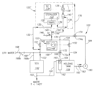
Fig. 3 shows a schematic diagram of the recirculation system 100 of the
invention. The
recirculation system 100 is shown in an exemplary set up and operation. In
this exemplary set up
and operation, the recirculation system 100 is shown in use with an apparatus,
for example, a
sterilizer system 120' (shown in large broken lines), that is typically
modified for use with the
recirculation system 100.
The sterilizer system 120' includes a sterilizer 122 (similar to the
sterilizer 22 detailed
above and shown in Figs. 1 and 2) with steam traps 130 (similar to the steam
traps 30 detailed
above and shown in Figs. 1 and 2). The sterilizer 122 is coupled to the steam
traps 130, similar
to the sterilizer 22 and steam traps 30, detailed above and shown in Figs. 1
and 2. A drain line
132 extends from the steam traps 130, exits the sterilizer system 120', and
connects to the
recirculation system 100 at the line 153, for passing water to the steam
collapsing unit (SCU)
142 (detailed below). The connection to the line 153 is typically downstream
of the valve 1 S 1.
A sterilizer controller (SC) 134 (or sterilizer control unit) is electrically
connected to the
sterilizer 122 and a valve (V2) 136, for example, a solenoid valve. A feed
line 138, extending
from the edge of the sterilizer system 120' (to receive the recirculation line
176, detailed below)
6
CA 02498615 2005-02-28
to an ejector 140, is controlled by the valve (V2) 136 along the feed line
138. A chamber drain
line 139 (similar to the chamber drain line 39 detailed above) connects to the
ejector 140. The
ejector 140 is similar to the ejector 40 detailed above, as pulls a vacuum in
the chamber (not
shown) of sterilizer 122, through the chamber drain line 139, by using with
flowing water.
A steam collapsing unit (SCU) 142 (also serving as a fluid tempering unit) is
also located
along the recirculation system 100, to temper water that is too hot, typically
greater than 140°
Fahrenheit, typically for release to the outside environment. This steam
collapsing unit (SCU)
142 is, for example, the unit disclosed in commonly owned U.S. Patent
Application S/N
10/374,127 (U.S. Patent Application Publication 2004/0166020, entitled: Steam
Collapsing
Apparatus and System, published August 26, 2004), this patent application
incorporated by
reference herein, and which is commercially available as the WATER-MIZERTM
from
Continental Equipment Company, Lawrence, Kansas 66044.
In Fig. 3 and also in Fig. 4, electrical connections are shown in short broken
lines. These
electrical connections are typically wired links, but could also be wireless
links or combinations
of wired and wireless links. While the significant electrical connections are
shown, other
components are typically electrically connected to each other. Additionally,
in Figs. 3 and 4,
typical fluid flow paths, illustrative of normal operation of the system 100
and the exemplary set
up, are indicated by arrowheads and arrows.
The system 100 includes an intake line 144' that is continuous with a drain
line 144
(similar to line 44 detailed above), extending from the ejector 140. The
intake line 144' receives
effluent, for example, fluid, such as water, steam, steam condensate or
combinations thereof,
through an inlet or opening 145, as discharged from a drain line 144 at the
ejector 140.
7
CA 02498615 2005-02-28
A temperature probe (TP) 146 (typically controlled by a processor-based logic
controller
or other computer-type device, or the like, associated therewith) monitors the
temperature of the
effluent flowing through the intake line 144'. This temperature probe (TP) 146
is electrically
linked (either directly or through the processor-based logic controller
associated therewith), by
wired or wireless links, or combinations thereof (shown in short broken
lines), to a switch 148,
that is automatic, and moves between open (Fig. 3) and closed (Fig. 4)
positions. The
temperature probe 146 is typically programmable to threshold temperatures, so
as to signal the
switch 148, when the effluent flow has moved above or below the threshold
temperature for
alternately, based upon the programming of the logic controller, has moved up
to at least the
threshold temperature, or has moved down to at least the threshold
temperature), in order to
move the switch 148. The switch 148 is typically housed in an entry device
(ED) 149.
The threshold temperature for the temperature probe 146 can be entered by an
operator
into the entry device (ED) 149, that is electrically linked to the temperature
probe (TP) 146. For
example, when used with a conventional sterilizer, sterilizer unit or
sterilizer system, the
threshold temperature is typically set to approximately 70° to
approximately 95° Fahrenheit,
although temperatures up to approximately 140° Fahrenheit are also
considered to be acceptable,
as they are within building codes (as detailed above).
The switch 148 is electrically linked to valves 151, 152, typically solenoid
valves. These
valves 151, 152 are positioned along flow lines 153, 154, and control the flow
through these
lines 153, 154. The lines 153, 154 define pathways to the steam collapsing
unit (SCLn 142 and
a water holding tank 156, respectively.
8
CA 02498615 2005-02-28
For example, the switch 148 is normally open (as shown in Fig. 3), such that
in a typical
operation, when the switch is in the OPEN position, the valve 151 controlling
the flow path to
the steam collapsing unit (SCU) 142 is normally open, while the valve 152,
controlling the path
to the holding tank 156 is normally closed. However, should the temperature
probe (TP) 146
detect effluent below the threshold temperature, the switch 148 will move to
the CLOSED
position (as shown n Fig. 4), whereby the valve 151 controlling the flow path
to the steam
collapsing unit (SCU) 142 closes, and the valve 152, controlling the path to
the holding tank 156
opens.
The water holding tank 156 is a vessel, container, or the like for holding
fluid (water)
sufficient for one or more recirculation cycles. The tank 156 includes a float
valve (FV) 160, that
rides in a column 162. When the water level in the holding tank 156 has risen
to a sufficient
level, the float valve (FV) 160 closes off an opening 164 to a sub-line 166,
that is joined to an
inflow line 168 for municipal or city water, and a bypass line 170, at a valve
172. The inflow
line 168 includes a branch line 168a, through which city water is supplied to
the steam collapsing
1 S unit (SCU) 142, and a strainer 168b, to remove mineral deposits and the
like, from the inflowing
city water.
The valve 172 is, for example, a three way ball valve, that is manually set by
an operator,
typically by turning a handle 172a (shown in detail in Figs. 5 and 6). The
typical position of this
valve 172 is such that city water normally flows from outside the system 100
(indicated as CITY
WATER), through the inflow line 168 and the sub-line 166, into the holding
tank 156. The valve
172 may also be automatic.
9
CA 02498615 2005-02-28
The bypass line 170 terminates in a valve 174, that is also, for example, a
three-way
manually set ball valve (set the user turning a handle 174a), similar to valve
172 (detailed
immediately above). In its typical and normal operating position, the valve
174 is closed off to
fluid flow from the bypass line 170, and is open to fluid flow through the
outflow line 184.
A recirculation line 176 extends from the valve 174 to the feed line 138, and
attaches to
the feed line 138. The recirculation line 176 supplies water to the ejector
140, through the feed
line 138, when the valve (V2) 136 is open (in an open position). The water
passing through the
recirculation line 176 and the feed line 138 is at pressures sufficient for
the ejector 140 to pull the
vacuum necessary to maximize sterilization in the sterilizer 122, as detailed
above. The valve
(V2) 136 is normally closed (in a closed position) prohibiting water from
flowing through the
feed line 138. The valve (V2) 136 opens when it receives a signal from the
sterilizer controller
(SC) 134, that typically controls the valve (V2) 136 opening in accordance
with a predetermined
program, for fluid (water) delivery to the sterilizer system 120'.
The water holding tank 156 is coupled to a pump (P) 180 along a line 182. A
one way
1 S valve 183 is also along the line 182 and serves to prevent fluid from
flowing back into the
holding tank 156. The pump (P) 180 provides a pumping force sufficient to
recirculate the fluid
(water), stored in the holding tank 156 back to ejector 140 (or other
applicable component,
apparatus or the like), through the outflow line 184, the valve 174 (in its
normal position), the
recirculation line 176, the valve (V2) 136 (in its open position), and the
feed line 138. The
pump (P) 180 is, for example, a Grundfos Pump Model MQ3-45.
The pump (P) 180 typically includes a pressure sensor, detector or the like
(not shown)
and control logic, typically processor based (not shown), associated
therewith. This pressure
/~.
CA 02498615 2005-02-28
sensor is such that it can be programmed (either at the factory or by a user)
to detect a threshold
pressure in the outflow line 184. When the pressure in the outflow line 184
falls below the
threshold pressure (or alternately, depending upon the programming of the
control logic, when
the pressure falls to at least the threshold pressure), the pump (P) 180 is
activated. The pressure
drop in the outflow line 184 is caused by the sterilizer controller (SC) 134,
opening the valve
(V2) 136, releasing the water pressure in the lines 184, 176, 138, as the
water therein moves into
the ejector 140 (the pump (P) 180, while inactive, serving as a closed valve
for the line 184).
The now activated pump (P) 180 recirculates fluid (water) from the holding
tank 156,
through the outflow line 184, through the recirculation line 176 and through
the feed line 138 (at
least the outflow 184 and recirculation 176 lines forming a fluid supply line
for the system 100),
to the ejector 140. Once the sterilizer controller (SC) 134 has allowed an
amount of water into
the ejector 140, as typically preprogrammed therein (for example, this
predetermined amount of
water sufficient for at least one recirculation cycle), the valve (V2) 136 is
closed, as signaled by
the sterilizer controller (SC) 134. The closing of the valve (V2) 136 causes
the water pressure in
the outflow line 184 to increase and return to a pressure above the preset
threshold pressure (or
alternately, depending upon the programming of the control logic, when the
pressure rises to at
least the threshold pressure), whereby the pump (P) 180 deactivates (shuts
off).
Should the pump (P) 180 become non functional, there is a bypass. In this
case, the
valves 172 and 174 would be manually set, such that there is a flow path for
city water from the
inflow line 168, through the bypass line 170, through the recirculation line
176, and to the feed
line 138. The sub-line 166 and the outflow line 184 would be closed off by the
respective valves
172, 174. As the valve (V2) 136 is under the control of the sterilizer
controller (SC) 134, a
11
CA 02498615 2005-02-28
circulation of city water to the ejector 140 would occur when the sterilizer
controller (SC) 134
opens the valve (V2) 136, in accordance with its program(s). The municipal
water pressure is
sufficient to drive the water along this path of lines 168, 170, 176 and 138,
and to pull the
vacuum in the ej ector 140.
An overflow line 190 extends from the water holding tank 156 and goes to the
drain line
192, that is also the drain line for the steam collapsing unit (SCU) 142. The
overflow line 190
connects to the tank 156 at its upper end. Overflow conditions, where fluid
exits through the
overflow line 190, may occur, when the tank 156 is full (the float valve (FV)
160 is at its highest
elevation in the column 162 blocking the opening 164 of the tank 156) and
there is not any
pumping by the pump (P) 180 to relieve the tank 156 of water. Through the
drain line 192,
water flows into a municipal waste or sewer system or the like of the outside
environment
(indicated in Figs. 3 and 4 as WASTE).
Turning also to Fig. 5, there is shown a perspective view of the recirculation
system 100,
in particular, illustrating the holding tank 156. All components shown in the
schematic diagrams
of Figs. 3 and 4 are numbered identically in this drawing figure. Additions
are noted here.
The holding tank 156 is typically a square or rectangular cube and, for
example, has a
capacity of approximately seven gallons. Electrical lines 146a, 151a and 152a
(corresponding to
the broken lines of Figs. 3 and 4) extend from the switch (not shown) in the
entry device (ED)
149 to the temperature probe (TP) 146, and valves 151, 152, respectively. The
three way valve
172 includes the manually moveable handle 172a (also on Figs. 3 and 4). A
similar manually
moveable handle 174a (Figs. 3 and 4), is also present on the three way valve
174 (Figs. 3 and 4).
12
CA 02498615 2005-02-28
Turning also to Fig. 6, this drawing figure is similar to Fig. 5 (and
components are
numbered identically), but shows a perspective view based on the steam
collapsing unit (SCL~
142. The steam collapsing unit 142 includes a body 142a, that provides it with
its cylindrical
shape.
Turning back to Figs 3 and 4, exemplary operations of the system 100 are
detailed. In
Fig. 3, the switch 148 is in its normal or open position, such that the valve
151 is open (valve 152
is closed), and accordingly, the effluent from the drain line 144 is "hot", as
determined by the
temperature probe (TP) 146. In Fig. 4, the switch 148 is in its closed
position, such that the valve
152 is open (and the valve 1 S 1 is closed), and accordingly, the effluent
from the drain line 144 is
"cold", as determined by the temperature probe (TP) 146.
In Fig. 3, the "hot" effluent in line 144' flows through the line 153 to the
steam
collapsing unit (SCLTJ 142. In the steam collapsing unit (SCLn 142, the
effluent is tempered, as
described in U.S. Patent Application S/N 10/374,127 (U.S. Patent Application
Publication
2004/0166020), for its safe release to the outside environment, through the
drain line 192.
In Fig. 4, the "cold" effluent in line 144' flows through the line 154 to the
holding tank
156. The effluent fills the tank 156 and it may also be filled by city water,
from the inflow line
168, through the sub-line 166. When the pump (P) 180 senses a pressure drop,
below a threshold
pressure, in the outflow line 184, caused by the valve (V2) being opened (and
the water in the
line 184 moves out of the line 184 toward the ejector 140), as controlled by
the sterilizer
controller (SC) 134, the pump (P) 180 activates. The pumped fluid (water)
leaves the tank 156
and is delivered or recirculated to the ejector 140 at pressures sufficient to
pull a vacuum in the
sterilizer 122.
13
CA 02498615 2005-02-28
Alternately, should the tank 156 fill and the pump (P) 180 fail to operate,
excess water
will exit the tank 156 through the overflow line 190.
Should a the pump (P) 180 be inoperative, a bypass of the pump, whereby city
water is
delivered to the ejector 140, at pressures sufficient for the ejector to pull
the requisite vacuum in
the sterilizer 122 (as detailed above), may be performed manually. In this
bypass, valves 172
and 174 are opened, to create a pathway from the inflow line 168, through the
bypass line 170,
through the recirculation line 176, and through the feed line 138, to the
ejector 140. The valve
(V2) 136 along the feed line 138 is opened (and closed) by the sterilizer
controller (SC) 134 in
accordance with its program(s).
While preferred embodiments of a recirculation system and methods for its use
have been
shown and described above, so as to enable one of skill in the art to practice
the present
invention, the preceding description is intended to be exemplary only. It
should not be used to
limit the scope of the invention, which should be determined by reference to
the following
claims.
14