Note: Descriptions are shown in the official language in which they were submitted.
CA 02498750 2005-02-28
_Pa~2.
INTERNAL SHOULDER $ARS FOR SQUEEZE CHUTES AND THL LIKE
This invention is in the field of equipment for handling livestock animals
such as cattle,
and in particular chutes for confining animals.
BACKGROUND
Chutes are used for confining cattle and like animals to allow for various
procedures such
as testing, vaccination, branding, and so forth. Conventional squeeze chutes
include a
squeeze mechanism to apply pressure to the sides of the animal. A headgate at
the front
end of the chute comprises a pair of bars that move together behind the
animal's head on
each side of the neck. The bars may be curved to follow the contours of the
neck, and to
prevent harts to the animal the bars do not close tightly against the neck
such that the
animal can move forward the distance between the head and shoulders. United
States
Patent Number 5,111,773 to Akuis discloses a typical cattle chute.
In order to prevent such forward and rearward movement of the animal, which is
desirable for example to facilitate injections of medicine into the preferred
neck area of
the animal, head bars have been provided forward of the conventional headgate
bars.
United States Patent Numbers 4,517,924 to McCan et al, and 6,bb6,169 to Dehod
disclose such head bars forward of the conventional headgate. United States
Patent
CA 02498750 2005-02-28
-Page3-
Numbers 3,777,715 to Hill et al. and 4,162,685 to Knappenberger disclose
further head
confining mechanisms located in front of the conventional headgate.
SUMMARY OF THE INVENTION
s
It is an object of the present invention to provide a headgate that overcomes
problems in
the prior art.
The present invention provides, in a first embodiment, a shoulder bar
apparatus for
attachment inside an animal chute comprising a headgate at a front end of a
chute frame,
and side panels rearward of the headgate, the headgate and side panels movably
mounted
on the chute Frame and operative to temporarily one an animal with a neck of
the
animal extending through the head gate and side panels adjacent to a body of
the animal.
The shoulder bar apparatus comprises right and left substantially vertically
oriented
t5 shoulder bars adapted to be movably mounted to corresponding sides of the
chute frame
rearward of the headgate, the shoulder bars each having a top end located
above a neck
location and a bottom end below the neck location. A shoulder bar control is
operative to
substantially simultaneously move the shoulder bars from an open position,
where the
shoulder bars are located in proximity to corresponding right and left sides
of the chute
frame, to a closed position where the shoulder bars are located in proximity
to
corresponding right and left sides of the neck location and rearward of the
headgate a
CA 02498750 2005-02-28
-Page4-
distance substantially equal to a length of a neck of a conned animal, and a
lock is
operative to maintain the shoulder bars in the closed position.
The present invention provides, in a second embodiment, an animal chute
apparatus
comprising a headgate at a front end of a chute frame, and side panels
rearward of the
headgate. The headgate and side panels are movably mounted on the chute frame
and are
operative to temporarily confine an animal with a neck of the animal extending
through
the head gate and the side panels adjacent to a body of the animal. Right and
left
substantially vertically oriented shoulder bars are movably mounted to con-
esponding
t0 sides of the chute frame rearward of the hcadgate, the shoulder bars each
having a top
end located above a neck location and a bottom end below the neck location. A
shoulder
bar control is operative to substantially simultaneously move the shoulder
bars from an
open position, where the shoulder bars are located in proximity to
corresponding right
and left sides of the chute frame, to a closed position where the shoulder
bars are located
in proximity to corresponding right and left sides of the neck location and
rearward of the
headgate a distance substantially equal to a length of a neck of a cronfined
animal. A lock
is operative to maintain the shoulder bars in the closed position.
The shoulder bars of the present invention minimize movement of the animal in
the chute
2o and prevent forward and rearward movement of the confined animal. On modern
conventional squeeze chutes, doors are typically provided in the sides of the
chute just
CA 02498750 2005-02-28
- Page S -
rearward of the headgate to provide access to the neck for injections. An
animal in a
chute with the added shoulder bars of the invention can not move back and
forth, and so
injections in the neck are more readily performed
The internal shoulder bars of the present invention can be provided for
installation on
existing chutes as an after market modification, or can readily be added at
the factory
when building new chutes without requiring any substantial changes to the
design of the
conventional chute, thus reducing start-up costs. A chute with such internal
shoulder bars
is more compact than one with prior art shoulder bars extending in front of
the
to conventional headgate.
DES~~PTION OF THE DRAWINGS:
While the invention is claimed in the concluding portions hereof, preferred
embodiments
are provided in the accompanying detailed description which may be best
understood in
conjunction with the accompanying diagrams where like parts in each of the
several
diagrams are labeled with like numbers, and where:
Fig. 1 is a schematic top view of an animal in a conventional squeeze chute of
the
2o prior art with the headgate and side panels in a closed position confining
the
animal;
CA 02498750 2005-02-28
- Page 6 -
Fig. 2 is a schematic top view of an animal entering the squeeze chute of Fig.
1
with the headgate and side panels in an open position to allow the animal to
enter
the chute;
Fig. 3 is a schematic top view of an animal in the squeeze chute of Fig. 1
with the
headgate and side panels in a closed position, and showing the shoulder bars
of
the invention in a closed position, confining the animal;
to Fig. 4 is a schematic top view of an animal entering the squeeze chute of
Fig. 1
with the headgate and side panels in an open position, and showing the
shoulder
bars of the invention in an open position, to allow the animal to enter the
chute;
Fig. 5 is a schematic side view of an animal in the squeeze chute of Fig. 1
with the
headgate and side panels in a closed position, and showing the shoulder bars
of
the invention in a closed position, confining the animal;
Fig. 6 is a schematic top view of a top guide for the shoulder bars with the
shoulder bars in the closed position;
CA 02498750 2005-02-28
Page 7 -
Fig. 7 is a schematic top view of the top guide of Fig. b with the shoulder
bars in
the open position;
Fig. 8 is a schematic front view of a mechanism for moving the shoulder bars
between the open and closed position, and for locking the shoulder bars in a
selected position, with the shoulder bars shown in the closed position;
Fig. 9 is a schematic side view of an alternate shoulder bar and guide
arrangement;
to
Fig. 10 is a schematic top view of an alternate mechanism for moving the
shoulder bars between the open and closed position.
DETAILED~ESCRIPTION OF TIC ILLUSTRATED EMBODIMENTS:
13
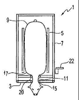
Fig. 1 schematically illustrates an animal squeeze chute 1 such as are known
for use in
animal husbandry. Such chutes comprise a headgate 3 at a front end of a chute
frame 7,
and side panels 5 rearward of the headgate 3. The headgate 3 and side panels 5
are
movably mounted on a chute frame 7 and are operative to temporarily confine an
animal
20 9 with a neck 11 of the animal 9 extending through the head gate 3 and side
panels 5
CA 02498750 2005-02-28
_Pa8e8_
located adjacent to a body of the animal 9. To release the animal 9, the
headgatc 3 and
side panels 5 are moved away from the animal in the directions indicated by
arrows R.
Fig. 2 illustrates an animal 9 entering the chute 1 in the forward direction
F. While the
headgate 3 is moved in the forward direction indicated by arrows R to release
the animal
as illustrated in Fig. 1, prior to another animal entering the chute the
headgate is typically
moved backward to the entrance position illustrated in Fig. 2, such that when
the animal
9 enters, its head 13 passes between the bars 15 of the headgate 3, but its
shoulders 17
contact the bars 15, and push the headgate 3 to the closed position
illustrated in Fig. 1.
l0 The headgate 3 latches in the closed position as the animal 9 moves
forward.
Figs. 3 - 5 illustrate the chute 1 of Fig. 1 with an embodiment of the
shoulder bar
apparatus of the invention mounted thereon. The shoulder bar apparatus
comprises right
and left substantially vertically oriented shoulder bars 20 movably mounted to
t5 corresponding sides of the chute frame 7 rearward of the headgate 3, the
shoulder bars 20
have a top end 20A located above the location of the neck 11 and a bottom end
20B
below the neck location.
A shoulder bar control 22 mechanism is operative to simultaneously move the
shoulder
zo bars 20 from the open position illustrated in Fig. ~ where the shoulder
bars 20 are located
in proximity to corresponding right and left sides of the chute frame 7, to
the closed
CA 02498750 2005-02-28
-Page9-
position illustrated in Fig. 3 where the shoulder bars 20 are located in
proximity to
corresponding right and left sides of the location of the neck 11. The
shoulder bar
control mechanism 22 includes a lock mechanism such that the shoulder bars 20
can be
maintained in the closed position.
In the animal chute 1 with the attached shoulder bar apparatus of the
invention the animal
enters the chute 1 and the headgate 3 closes to confine the neck lI from side
to side
movement, however the animal can still move forward and rearward the length of
its
neck between the shoulders 17 and head 13. The animal 9 is moving forward when
the
headgate 3 latches closed, and the animal 9 is forced to stop. Typically an
animal 9 such
as a cow will try to reverse direction and back up when forward motion is thus
stopped.
When the animal backs up such that its head 13 is against the headgate bars
15, the
shoulder bar control mechanism 22 can be operated to move the shoulder bars 20
to the
closed position, securing the animal from forward and rearward motion. 1f the
animal 9
is does not back up on its own, a wave of the hand or tap on the head 13 will
generally
cause the animal to back up so the shoulder bars 20 can be moved to the closed
position.
Figs. 6 - 8 schematically illustrate a control mechanism 22 for moving the
shoulder bars
laterally in a direction perpendicular to the side panels 5 from the open
position of Fig.
20 7 to the closed position of Figs. 6 and 8. The control mechanism 22
comprises first pivot
arms 30 each pivotally attached to the frame 7 by hinges 32 at one end and
pivotally
CA 02498750 2005-02-28
- Page 10 -
attached to a vertical pivot bar 34 by sleeves 36 at the opposite end. Sec4nd
pivot arms
40 each pivotally attached to the pivot bar 34 by sleeves 42 at one end and
pivotally
attached to the shoulder bar 20 by sleeves 46 at the opposite end, To minimize
space, the
pivot bar 34 is somewhat smaller in diameter than the shoulder bar Z0.
A linkage 50 is attached to the frame 7 such that pulling down on the control
handle 23
pulls the shoulder bars 20 together and into the closed position. Top ends of
the shoulder
bars 20 move along a top guide 52 comprising front and rear plates 52A, 52B
fixed to the
chute frame 7 and bottom ends of the shoulder bars 20 move along a bottom
guide 54
fixed to the chute floor 56 when moving from the open position to the closed
position.
The guides 52, 54 prevent forward movement of the shoulder bars 20 when the
animal
pushes on them. The illustrated top guide S2 also prevents rearward motion of
the
shoulder bars 20, however any significant rearward movement of the animal is
prevented
by the headgate bars positioned against the neck directly behind the animal's
head.
To help support the shoulder bars 20 vertically, a tab 53 extends from each
shoulder bar
over the top of the front plate 52A and bears against, and slides along, the
top of front
plate 52A. Alternatively Fig. 9 illustrated an alternative wherein a groove
153 is
provided in the shoulder bar 120 and the front member 152A of the top guide is
provided
2o by a tube or like member engaging the groove 153. Thus the front and rear
members
CA 02498750 2005-02-28
- Page 11 -
152A, 152B of the top guide can be closer together, reducing the room needed
for the
apparatus.
The shoulder bars 20 are locked in the closed position by a lock comprising a
ratchet
s mechanism 58, which may be released by applying closing pressure on the
control handle
23 and releasing the catch. The ratchet mechanism 58 conveniently also is
operative to
maintain the shoulder bars 20 in any intermediate position between the open
position and
the fully closed position, such that various widths of animal necks can be
accommodated.
In the illustrated embodiment the shoulder bars 20 are biased toward the open
position by
t0 a spring 60 connected to the linkage 50 by a cable 62. Thus when the catch
on the ratchet
mechanism 58 is released, the shoulder bars 20 are urged toward the open
position. The
first and second pivot arms 30, 40 can also be made adjustable to allow the
distance
between the shoulder bars 20 when in the closed position to be adjusted if
required.
15 It is contemplated that other mechanisms could readily be adapted for
moving the
shoulder bars 20 between the open and closed positions and locking them at the
desired
position. Fig. 10 illustrates an alternate embodiment of the control mechanism
222
wherein the shoulder bars 220 are each pivotally attached to the chute frame 7
at a pivot
location 208 by an arm 210. The shoulder bars 220 are located in proximity to
2o corresponding right and left sides of a rear face of the headgate 3 when in
the open
position OP, and move pivotally inward and rearward to the closed position CP.
Cables
CA 02498750 2005-02-28
- Page 12 -
and linkages such as are known in the art can be provided to simultaneously
move the
shoulder bars 220 between the open and closed positions and lock same where
desired. A
bias element could be readily provided to urge the shoulder bars 220 to the
open position
when the lock was released. Top and bottom guides can be provided as required.
The internal shoulder bars of the present invention can be provided for
installation on
existing chutes as an after market modification, or can readily be added at
the factory
when building new chutes without requiring any substantial changes to the
design of the
conventional chute, thus reducing start-up costs. A chute with such internal
shoulder bars
to is more compact than one with prior art shoulder bars extending in front of
the
conventional headgate.
The foregoing is considered as illustrative only of the principles of the
invention.
Furtlier, since numerous changes and modifications will readily occur to those
skilled in
the art, it is not desired to limit the invention to the exact construction
and operation
shown and described, and accordingly, all such suitable changes or
modifications in
structure or operation which may be resorted to are intended to fall within
the scope of
the claimed invention.