Note: Descriptions are shown in the official language in which they were submitted.
CA 02499051 2009-10-30
SURFACE AERATION IMPELLERS
FIELD OF THE INVENTION
The present invention relates generally to rotating impellers. More
specifically, the invention relates to surface aeration impellers that rotate
on a veitical
axis near the surface of a body of liquid in a tank causing liquid to be
sprayed into the
gas above the liquid and gas to be entrained into the liquid by the liquid
spray
impinging onto the liquid surface.
BACKGROUND OF THE INVENTION
In a number of industrial processes it is desirable to enhance the mass
transfer
of a gas into a liquid. Much of this need results from biochemical oxidation
processes
which use aerobic microbes. Aerobic microbes are employed because they are
able to
convert a raw material into a higher value material. Some examples include
aerobic
fermentation processes for manufacturing fragrances, flavors, and
phaimaceutical
components. Perhaps an even more important process is the aeration of sewage
and
other wastewater streams. What all these processes using aerobic microbes have
in
common is the need for oxygen to be d:issolved into the liquid in order for
the
microbes to be able to convert the raw material into the desired result. Since
the
microbes work most efficiently when there is an adequate level of dissolved
oxygen
available in the liquid, it is typically desirable to transfer additional
amounts of
oxygen or air into the liquid. This can be acconlplished in a nunlber of ways
but the
two most common techniques are gas sparging and surface aeration. In a gas
sparging
procedure, a gas (e.g. air or oxygen) is bubbled tlirougli the liquid in a
manner that
increases the amount of dissolved oxygen in the liquid. In contrast, surface
aeration
1
CA 02499051 2005-03-15
WO 2004/025125 PCT/US2002/029280
uses an impeller located at the surface of the liquid to agitate or spray the
liquid into
the gas. The spray subsequently impinges on the liquid surface which also
entrains
gas into the liquid surface.
One of the basic procedures for the treatnient of sewage and other wastewater
streams is lcnown as the activated sludge process, which was discovered or
invented
more than seventy years ago. It is a biochemical type of reaction, involving
the mass
transfer of oxygen into water, and then the transfer and use of that dissolved
oxygen
to support the growth of aerobic microorganisms suspended in the water. These
microorganisms, known as the biomass, oxidize the organic materials in the
wastewater in different ways to eliminate the biochemical oxygen demand (BOD)
of
the wastewater.
The original activated sludge process involved introducing air from a blower
through various forms of diffuser devices located in the bottom of the
aeration tank or
basin. These devices generally have low oxygen-transfer efficiency and poor
solids-
suspension characteristics. More than forty years ago, a different approach
was taken
to aeration in the activated sludge process. This different approach was known
as
mechanical surface aeration. This technique made use of a mechanical agitator
operating at the liquid surface to throw or spray liquid into the air and to
induce
entraimnent of air into the liquid surface, without the use of a compressor
and the
diffusers. Since that time, a fairly large number of different designs for
surface
aeration impellers have been introduced, both for the purpose of increasing
the
oxygen-transfer efficiency and also, secondarily, if possible, to improve
liquid mixing
and solids suspension. The problem of solids suspension, however, has an
obvious
limitation because of the remoteness of the surface aeration impeller from the
tank
bottom where the biomass solids tend to settle if the bulk liquid in the tank
is not
adequately mixed.
The standard measure of aeration efficiency is the number of pounds of
oxygen transferred into the liquid per hour per horsepower of energy used to
operate
the aeration system. This measure is known as the Standard Aeration Efficiency
(SAE). The SAE for current state of the art surface aeration devices ranges
from
about 2.0 to about 3.3 pounds of oxygen per hour per horsepower in the larger
aerator
sizes. In smaller sizes, the efficiency values can be somewhat higher. Since
wastewater treatment plants are pure cost centers (i.e. they do not sell a
product) and
since electric power is one of the main operating costs in such a plant, the
oxygen-
2
2
CA 02499051 2009-10-30
transfer efficiency performance of such aerators -is extremely important,
especially in
the larger plants. This need has led to a nunlber of attempts at producing
surface
aeration inipeller designs with greater oxygeri transfer efficiency.
Typical of state of the art surface aeration impellers are those shown in U.S.
Pat. Nos. 3,479,017 to Thikotter; 3,576,316 and 3,610,590 to Kaelin; and
3,741,682 to
Robertson; 4,066,383 to Laltin; 4,074,953 to Budde et al.; 4,151,231 to
Austin;
4,334,826 to Connolly et al.; 5,522,989 to Hove; and 5,988,604 to Mc Whirter.
Thilcotter discloses a surface aeration impeller for use in an activated
sludge
process. Thikotter's aerator comprises a flat, circular impeller disc having a
plurality
of iinpeller blades depending from the undersurface of the disc. The blades
are
generally flat, positioned radially and have a height that decreases from its
imier edge
to its outer edge. This design principally focuses on spraying the liquid and
does not
provide niuch up-puniping action or mixing of the tai-dc liquid content
resulting in
relatively low efficiency of the system. Robertson and Austin also disclose
surface
aeration impellers having multiple blades located on the underside of a disc.
Their
blades are radial or approximately radial and generally flat but have a
horizontal plate
secured to the lower edge of each blade. Again, these designs primarily foctis
on
throwing or spraying of the liquid and do not provide much up-pumping action
and
mixing of the body of liquid in the tank.
Unlike Thikotter, Roberston, and Austin, Lakin and Connolly disclose various
forms of surface aeration impellers having primarily vertically curved blades.
Most
seem to have multiple blades on a disc-shaped mounting member. Kaelin and
Budde
et al. also teach surface aerator designs. The blades of Budde et al. are
radial and
Kaelin show other designs representative of the state of the art. The design
of Budde
et al. does not provide much niixing action and Kaelin in addition suffers
from the
disadvantage of being difficult to manufacture.
Hove teaches a device and method for aerating wastewater. The device has
multiple blades positioned on a disc=shaped mounting meniber. The blades
appear to
be entirely radial. Hove's blades are unique compared with the above patents
in that
they are located both above and below the disc-shaped mounting niember.
3
CA 02499051 2009-10-30
McWhirter `604 teaches a surface aeration impeller that is an axial flow
impeller that may have either pitched blade turbine or airfoil shaped blades.
The
blades of the McWhirter patent are not mounted to the underside of a disc-
shaped
3a
CA 02499051 2005-03-15
WO 2004/025125 PCT/US2002/029280
mounting member Additionally, while the upper section of the `604 blades are
not
strictly radial, the lower section is radial (at least at one point). This
impeller does
provide some up-pumping and mixing action but still leaves room for iinproved
liquid
pumping and oxygen transfer efficiency.
Although such surface aeration devices as discussed above have functioned in
a generally satisfactory inanner, problems have been experienced with
excessive
splashing and misting, insufficient liquid pumping, mixing and circulation,
and
clogging of the impellers during operation. Accordingly, there continues to be
a need
for improved designs that increase the efficiency of the aeration process
and/or
address some of these problems. In particular, surface aeration impeller
designs and
operational characteristics that increase the oxygen transfer efficiency into
the liquid
and thereby reduce operating costs are especially desirable.
Many of the limitations associated with prior art surface aerator impeller
designs result from an insufficient understanding of the fundamental
mechanisms and
fluid dynamics of surface aeration. The current state-of-the-art oxygen mass
transfer
analysis for surface aerators is essentially limited to the simple, idealized
model
employed in the ASCE Standard for the Measurement of Oxygen Transfer in Clean
Water. This oversimplified and limited model has been used for decades to
characterize the oxygen mass transfer performance of surface aerators. A more
realistic and rigorous model has been developed by McWhirter et al. in "Oxygen
Mass Transfer Fundamentals of Surface Aerators", Ind. Eng. Chem. Res. 34, 2644-
2654, 1995. This mechanistic model provides a more physically realistic
description
of the actual oxygen transfer mechanisms of surface aerators and separates the
oxygen
mass transfer process into two distinct zones: a liquid spray mass trapsfer
zone and a
surface reaeration mass transfer zone.
These two distinctly different mechanisms or zones are created by all generic
types of mechanical surface aerators. The liquid spray mass transfer zone 11
is
created in the immediate gas space surrounding the periphery of the surface
aeration
impeller where the liquid is discharged into the surrounding gas at high
velocity. The
surface reaeration mass transfer zone 13 exists primarily outside the spray
umbrella
and in the bulk liquid near the surface in the area that is circumferential to
the
periphery of the liquid spray mass transfer zone. The two zones are indicated
in
Figure 4. The liquid spray mass transfer zone can be reasonably characterized
and
modeled as a single-stage gas-liquid contacting zone wherein the liquid is
dispersed
4
4
CA 02499051 2005-03-15
WO 2004/025125 PCT/US2002/029280
into a virtually infinite, continuous gas phase of constant gas composition
above the
liquid surface. In contrast, the mechanism in the surface reaeration mass
transfer zone
is predominately characterized by oxygen transfer to a highly turbulent liquid
surface
containing entrained gas from the gas phase above the liquid surface. As the
liquid
spray zone impinges on the liquid surface of the tank, substantial gas bubble
entraiimient into the surface is accomplished and a "white-water" effect is
produced at
the periphery of the liquid spray impingement on the surface of the tanlc
liquid. The
surface reaeration mass transfer zone also includes the oxygen transfer to the
highly
turbulent liquid surface beneath the spray umbrella and thus includes all
oxygen
transfer to the surface liquid due to bubble entrainment and contact of the
highly
turbulent liquid surface with the gas above the liquid surface.
In contract to generally perceived prior opinion regarding the primary oxygen
transfer mechanism of surface aerators, the present inventors have
quantitatively
shown that about two-thirds of the oxygen transfer of surface aerators occurs
in the
surface reaeration mass transfer zone and only about one-third in the liquid
spray
mass transfer zone. This suggests that iinpeller designs that enhance oxygen
transfer
in the surface reaeration zone (e.g. by increasing tLirbulence and volume flow
rates)
may have a greater overall effect on the total oxygen transfer of the system
than
impeller designs that focus primarily on increasing oxygen transfer in the
spray zone
(e.g. by iinproving spray characteristics like height and distance). Thus, a
greater
understanding of the oxygen mass transfer mechanisms in surface aerators has
allowed the present inventors to independently analyze the oxygen transfer
process
within these two distinctively separate mass transfer zones leading to the
improved
surface aerator impeller designs as disclosed in this application. These new
designs
pump more liquid per unit of horsepower input through the liquid spray mass
transfer
zone and into the surface reaeration zone and thereby maximize the total
oxygen mass
transfer efficiency of the overall surface aeration system.
Accordingly, the following are selected objects of various embodiments of the
present invention:
It.is an object of the present invention to provide an improved surface
aeration
impeller having improved gas transfer rates into the liquid particularly in
the surface
reaeration nlass transfer zone of the system.
5
5
CA 02499051 2009-10-30
It is also an object of the present invention to enhance turbulence and gas
entrainment at the liquid surface created by the liquid spray of a sui-face
aeration
system.
It is an object of the present inveiition to provide an improved surface
aeration
impeller having reduced torque and increased rotational speed leading to
reduced
costs for motor and gear transmission equipment to rotate the impeller.
It is also an object of the present invention to provide an improved inlpeller
design having inereased liquid pumping capacity and efficiency.
SUMMARY OF THE INVENTION
According to the present invention, there is provided a surface aeration
impeller designed to rotate about an axis perpendicular to a static liquid
surface, said
impeller comprising a plurality of blades attached to the underside of a
generally disc-
shaped mounting member, said mounting member being parallel to said static
liquid
surface when mounted on a shaft for rotation about said axis; wherein said
impeller
blades comprise an upper generally vertical section attached to the underside
of said
disc-shaped mounting member, said vertical section having a generally
rectangular
surface with a lower inclined generally rectangular section attached to the
lower edge
thereof that extends downwardly and outwardly in the direction of rotation and
provides a substantial upward pumping flow of liquid onto the vertical section
when
said impeller is rotated.
According to the present invention, there is also provided a surface aeration
impeller designed to rotate about an axis perpendicular to a static liquid
surface, said
impeller comprising a plurality of blades attached to the underside of a
generally disc-
shaped mounting member, said mounting member being parallel to said static
liquid
surface when mounted on a shaft for rotation about said axis; wherein said
blades
are continuously curved downwardly and outwardly in the direction of rotation
and
begin at the top with a substantially vertical section and end with an
outwardly facing
6
CA 02499051 2009-10-30
non vertical section that will lie at least partially under the liquid surface
and provides
a substantially upward pumping flow of liquid when the impeller is rotated.
According to the present invention, there is also provided a surface aeration
impeller designed to rotate about an axis perpendicular to a static liquid
surface, said
impeller comprising a plurality of blades attached to the underside of a
generally disc-
shaped mounting member, said mounting member being parallel to said static
liquid
surface when mounted on a shaft for rotation about said axis;
wherein said blades comprise an upper generally vertical section having a top
edge connected to said disc-shaped mounting member and a bottom edge coupled
to a lower inclined section that extends downwardly and outwardly in the
direction of
rotation; and
wherein said bottom edge of said upper generally vertical section is
substantially parallel to said disc-shaped mounting member.
According to the present invention, there is also provided a surface aeration
impeller designed to rotate about an axis perpendicular to a static liquid
surface, said
impeller comprising a plurality of blades attached to the underside of a
generally disc-
shaped mounting member, said mounting rnember being parallel to said static
liquid
surface when mounted on a shaft for rotation about said axis;
wherein said blades comprise an upper generally vertical section and a lower
inclined section that extends downwardly and outwardly in the direction of
rotation;
and
wherein said blades contain an endcap.
Preferably, the invention is an impi-oved surface aeration impeller for use in
a liquid filled tank that has a free liquid surface and an enclosed or open
gas space
above the liquid surface in the tank. The impeller is rotatable about an axis
perpendicular to the static liquid surface. the impeller has a plurality of
blades
mounted on the underside of a disc or disc-like surface. Each blade has a
multi-
faceted or curved geometry ranging from vertical at the point of attachement
to the
disc to partially inclined at the bottom. The blades are spaced
circumferentially about
6a
CA 02499051 2009-10-30
the axis and are disposed radially or at acute angles to radial lines from the
axis of
rotation of the impeller. The lower portions of the blades, which are less
inclined or
less vertical than the upper portions, are positioned below the static liquid
surface.
When the impeller is rotated, the lower portion of the impeller blade pumps
the liquid
up onto the vertical portion of the blades where the liquid is discharged into
a spray
umbrella in a direction upwardly from the static liquid surface and outwardly
away
from the rotating impeller.
BRIEF DESCRIPTION OF THE DRAWINGS
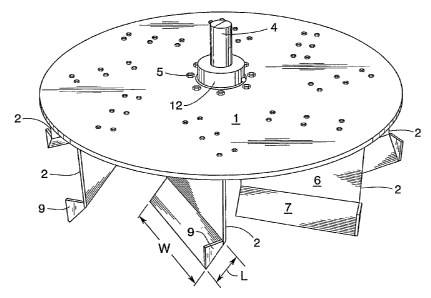
Figure 1 is a top plan view of a p:referred impeller design according to the
present invention.
Figure 2 shows an isometric view of an impeller in accordance with this
invention.
Figure 3 (A) is a profile view of a single blade with an endcap on the
trailing
edge. Figure 3 (B) shows the profile of a curved blade used in one enlbodiment
of the
present invention.
Figure 4 shows the surface aeration impeller in operation in a tank.
6b
CA 02499051 2005-03-15
WO 2004/025125 PCT/US2002/029280
DETAILED DESCRIPTION OF THE INVENTION
As mentioned above, approximately two-thirds of the oxygen transfer in a
surface aeration system occurs in the surface reaeration mass transfer zone 13
while
only about one-tllird occurs in the liquid spray mass transfer zone 11.
Further,
inaxiinum efficiency of a surface aeration system is not maximized by simply
increasing the discharge velocity or distance of travel of liquid spray in the
liquid
spray mass transfer zone as many prior art designs have assumed. This
discovery has
led the present inventors to focus on surface aerator designs that maximize
the total
oxygen transfer efficiency in both mass transfer zones with a particular
emphasis on
the surface reaeration mass transfer zone. This focus has led to surface
aerator
designs that operate significantly different that most prior art designs. In
the present
invention, the discharge velocity of the spray from the surface aeration
impeller is
much lower than most state-of-the-art surface aeration impellers. This results
in a
liquid spray that does not travel as high or as far as current commercial
designs. For
example, in preferred embodiments of the present invention the liquid spray
travels
only about 8 to 12 feet from the tip of the aerator impeller whereas current
state-of-
the-art surface aerators operate with a spray distance of about 15 to 18 feet
or more
from the tip of the inipeller. However, while the spray of the present
invention travels
a shorter distance, much more liquid is pumped through the liquid spray mass
transfer
zone per unit of horse power input. This is a result of the lower discharge
velocity of
the liquid spray from the tip of the iinpeller. The increased liquid flow also
creates
much more liquid flow and much more turbulence in the surface reaeration mass
transfer zone thus greatly increasing the oxygen transfer rate in the
reaeration zone.
This oxygen transfer increase in the surface reaeration zone more than
compensates
for any reduction in oxygen transfer rate within the liquid spray zone.
Accordingly,
the surface aeration impellers of the present invention are designed in a way
that
maximize the volume of liquid flow through the liquid spray and surface
reaeration
zones per unit of power input. This result is accomplished by dramatically
increasing
the up-pumping capability of the surface aeration impeller.
Thus, the surface aerator designs of the present invention have at least four
primary advantages that distinguish them over the prior art. These four
primary
advantages are:
7
7
CA 02499051 2005-03-15
WO 2004/025125 PCT/US2002/029280
1. The invention provides more liquid pumping and the spraying of more
liquid per unit of horsepower.
2. The invention provides higher oxygen transfer energy efficiency (SAE).
3. The invention provides better overall tank mixing and higher tank bottom
velocities for iniproved biomass solids suspension.
4. The invention operates at higher speed and lower torque which reduces the
equipment cost (gear reducer) wliile simultaneously providing all of the above
advantages.
Referring to the Figures, there is shown in Figure 1 a top view of an improved
surface aeration impeller according to the present invention. The impeller has
a
plurality of vertically extending blades 2 attached to the underside of a
rotatable disc
or disc-like mounting meinber 1. Each blade in the embodiment shown in Figure
1 is
disposed at an angle (a) of approximately 30-38 to a successive,
circumferentially
spaced radial line around the axis 3 of the impeller. In the exaniple shown in
Figure 1
there are eight blades spaced 45 apart. The blades 2 are more clearly shown
in
Figure 2 which is an isometric view of the iinpeller. These blades have
substantially
vertical portions 6 at the upward sections thereof. The blades 2 also have a
non-
vertical and non-horizontal lower section 7 which extends downwardly and
outwardly
in the direction of rotation of the iinpeller. This downwardly direction forms
angle (3
with the horizontal as shown in Figure 3 (A). The lower portion 7 of the
blades acts
as up-pumping pitched blade turbines to provide a high volume of liquid flow
to the
vertical upper portion 6 of the turbine blade which creates the liquid spray
umbrella
and liquid spray mass transfer zone 11.
The blades 2 in the present invention consist of at least two sections as
shown
in Figure 2: (1) the generally vertical upper portion 6 and (2) the non-
vertical but
inclined lower portion 7. In Figure 3 a third section, the top or mounting
section 8, is
also shown, but is optional. This top section is generally horizontal and
contains
holes for bolting 10 through corresponding holes in the mounting disc 1. This
section
is optional as other means of mounting the blades to the disc are possible.
For
example, the vertical section 6 could be directly welded to the mounting disc
1 or the
vertical section 6 could be mounted directly to a vertical flange on the
mounting disc.
These types of blades are similar in shape to those on pitched blade turbine
mixing
impellers.
8
8
CA 02499051 2009-10-30
For ease of manufacturing and mounting, the inventors have found that a
generally rectangular shape for all of these sections works well, though other
shapes
are certainly useable. In a preferred embodiment of the invention, the blades
are
made from a single rectangular piece of metal that has been creased in two
positions.
One crease is at a 90-degree angle and occurs near the top edge of the blade
to
provide the horizontal top portion 8 for easy mounting to the underside of the
mounting disc 1 and a substantially vertical upper section 6. The second
crease on
this embodiment occurs approximately two-thirds to three-forths of the way
down the
length of the entire rectangular piece of metal. This crease provides for the
downward
and outwardly (in the direction of rotation) extending lower section of the
blade 7.
The second crease forms angle 0 shown in Figure 3 (A). The angle (3 is from
about
to about 60 , preferably about 30 to 500, and most preferably is about 35 to
45 .
In a preferred embodiment of the invention the point at which the upper
section of the blades meets the mounting member is a straight line (i.e. the
upper
section of the blades are straight in the horizontal plane). In another
preferred
embodiment, all sections of the blades are planar (e.g. rectangular or
trapezoidal),
and are thus non-curved. Also the outer edge of the upper section is typically
contiguous with the outer edge of the disc-shaped mounting member. While the
20 inventors have found rectangular shaped blades most desirable, other shapes
are
useable without diverting from the spirit of the invention. It is important
for the blades
to begin at the top with a substantially vertical section and end with an
outwardly
facing (in the direction of rotation) non-vertical section that will lie at
least partially
under the static liquid surface. The incline and size of this lower portion is
such that it
is sufficient to provide a substantial amount of upward pumping flow of liquid
onto the
vertical section when the impeller is rotated. These requirements can be met
with the
two-section blade described above as well as by a multi-sectioned (more than
two)
blade and a continuously curved blade as shown in Figure 3B. Such continuously
curved blades can be termed "airfoil" shaped as described in US Patent
5,988,604,
9
CA 02499051 2009-10-30
especially Figure 6. The blades of the invention (both curved and non-curved)
preferably have an approximately constant width W along their entire length.
Such
blades can be made relatively.easily from a single rectangular piece of
material (e.g.
stainless steel).
The number of blades on the surface aeration impeller of the present
inveiltion
is generally in the range of about 6 to 12. The optimal 1lumber of blades will
depend
i
~
~
/
~
9a
CA 02499051 2005-03-15
WO 2004/025125 PCT/US2002/029280
on the specific application, however, smaller diameter impellers will
generally have
fewer blades and larger diameter impellers typically have 8 or more blades. In
preferred embodiments the number of blades is about 6-8 and in an even more
preferred einbodiment there are exactly 8 blades.
The positioning of the blades is important but can also vary considerably. The
inventors have found that positioning the blades radially under the disc-
shaped
mounting member produces a surface aeration impeller that out performs all
prior art
designs. However, the inventors have also discovered that positioning the
blades non-
radially - i.e. they do not project radially outward from the axis
perpendicular to the
static liquid surface - produces a surface aeration impeller with even greater
liquid
pumping capability and oxygen transfer efficiency. In this non-radial
embodiment,
the inner edge of the vertical section of the blade is pushed forward in the
direction of
rotation forming a non-zero angle (a) where a is defined as the angle between
a radial
line (through the outer edge of the vertical section) and the top edge of the
vertical
section 6 of the blade (see Figure 1). This angle is typically between 20 and
60 ,
preferably between about 25 and 50 and most preferably is about 30-45 .
Another
way of characterizing the positioning of the blades is that they are "swept
back" or
"off-axis" (i.e. non-radial). It is worth noting that in the non-radial
version of the
present invention there are no imaginary radial lines that lie on the surface
of any
blade section. In other words, there are no lines lying on the surface of any
blade
section which are also radial lines.
The size of the blades may also vary considerably. Referring to the figures,
the width W of the blades are within the range of about 0.1 to 0.4 the
diameter d of the
disc. Preferably W is less than 1/3 d and most preferably is about 0.2 to 0.3
d. The
height H of the vertical section of the blades are within the range of 0.05-
0.25 d,
preferably 0.1-0.2 d. The length L of the lower section of the blade is
typically less
than the height of the vertical section. Length L can be from 0.03-0.2 d,
preferably
less than 0.1 d or about 0.05 d. Finally, the width T of the optional top
section 8 for
mounting onto the disc is not critical as long as it allows for adequate
mounting, for
exaniple by bolts.
The blades of the invention have an optional additional segment known as an
endcap. The endcap 9 is shown in Figures 2 and 3 (A). The endcap is a
relatively flat
geometric piece positioned essentially perpendicular to the vertical section 6
and
connects the outer or trailing edges of botla the vertical section 6 and the
lower section
CA 02499051 2005-03-15
WO 2004/025125 PCT/US2002/029280
7. While the exact shape of the endcap can vary widely, the critical feature
of the
endcap is that it prevents liquid from flowing or "sliding" off the trailing
edge of the
blades below the vertical section 6 and simultaneously enhances the uplifting
or up-
puinping capability of the impeller. The inventors have found that an endcap
can
significantly increase the power delivered and simultaneously increase the
standard
aeration efficiency as the examples below denionstrate.
The blades 2 of the invention are mounted on the underside of a disc 1 or a
disc-lilce mounting member for mounting onto a shaft 4 that provides axial
rotation.
The disc provides a convenient method for positioning the blades radially or
at an
acute angle a as described above. The term disc-like is meant to include any
rotatable
mounting member having at least a top surface and a bottom surface and capable
of
attaching to the vertical section of the blades radially or at an angle a on a
bottom
surface. Included in the term "disc-like" are discs with a saw-toothed shaped
edge
and spoke and ring type structures.
Means for attaching the entire impeller (disc and blades) to the shaft is not
strictly part of the present invention as such means are well known to those
skilled in
the art of impellers. In a preferred embodiment, the inounting member is
substantially
a disc with a hole in the center for receiving and connecting to a rotatable
shaft 4
using an attachment means 12 which is attached to the disc with bolts 5 and to
the
shaft with pins.
The overall diameter of the impellers according to the invention will depend
on the specific application. In the case of sewage or wastewater aeration,
typical
diameters will be from about 50 to 100 inches. In other applications, the
diameter
could be much smaller, especially if the tank size is smaller. The size of the
impeller
is largely determined by the power required to meet the specific process
requirements
(i.e. the oxygen transfer rate) but can also be infhtenced by the size and
configuration
of the tank in which it is eniployed.
Examples
Inlpellers substantially as shown in Figure 1 were made and tested in a 49
feet
by 49 feet square tank containing about 17 feet of static liquid which
corresponds to
about 320,000 gallons of water. The test involved mounting the impeller on a
vertical
shaft connected to a power source and gear reduction means. All the inipellers
used
in the examples below contained 8 blades and the overall impeller diameter was
76.25
11
11
CA 02499051 2005-03-15
WO 2004/025125 PCT/US2002/029280
inches. Additionally, all blades tested had a width W of 20.5 inches and an
upper/vertical section height H of 12.5 inches. The horsepower used in the
examples
ranged from about 30 to 85 HP. The primary variables were: (1) the "off-axis"
angle
a, (2) the inclined lower section angle (3, (3) liquid submergence, where
submergence
is defined as the static liquid level in inches above the intersection of the
vertical and
lower sections of the blades, (4) length L of the lower section 7, and (5) the
presence
or not of an endcap 9.
Results were primarily determined by calculation of the standard aeration
efficiency (SAE) where SAE is defined as the number of pounds of oxygen
transferred into the liquid per hour per horsepower of energy used to operate
the
aeration system. These tests and calculations were made by using the ASCE
standard
procedure for detennining the SOTR (standard oxygen transfer rate) at 20 C
liquid
teinperature and 1 atm pressure. The results shown for more than one run are
given as
the average SAE for all runs.
Example 1:
This example illustrates one embodiment of the invention with an impeller
according to Figure 1 having a equal to 30 , (3 equal to 30 and a blade with
dimensions la = 12.5, w = 20.5, and l= 12.0 inches. The blade also does not
have an
endcap. The results (in SAE) show very good efficiency with some effect of
operating the impeller at various submergence levels.
a A d Submergence Endcap? # Runs SAE
30 12 in 1.0 in No 2 2.43
30 30 12 in 3.0 in No 1 2.74
30 301 12 in 5.0 in No 2 2.92
Example 2:
25 This example uses the saine impeller as demonstrated in Example 1 witli the
addition of an endcap. The top of the endcap was approximately one inch above
the
crease defining the intersection of the upper and lower sections of the
blades. The
results (in SAE) show that there is little effect in operating this embodiment
of the
12
12
CA 02499051 2005-03-15
WO 2004/025125 PCT/US2002/029280
impeller at various submergence levels. The SAE results clearly show the
dramatic
improvement in oxygen transfer efficiency possible with the use of the endcap.
a t l SubmerlZence Endcap? # Runs SAE
301 30 12 in 0.0 in Yes 3 3.39
30 30 12 in 4.0 in Yes 3 3.40
30 30 12 in 7.0 in Yes 2 3.32
Example 3:
This example uses the same impeller as demonstrated in Example 2 with the
exception that the length of the lower section was reduced from 12 inches to 8
inches.
The results (in SAE) show improved efficiency over prior art designs currently
advertised with SAE up to about 3.5. The SAE results also clearly show that a
smaller 8 inch lower blade section length gives higher transfer efficiencies
than a 12
inch section for this configuration.
a ~ 1 Submergence Endcau? # Runs SAE
301 30 8 in 0.0 in Yes 3 3.56
301 30 8 in 2.5 in Yes 1 3.78
30 301 8 in 5.5 in Yes 3 3.79
300 30 8 in 7.8 in Yes 1 4.11
Example 4:
This example is similar to Example 1 except that the lower section inclination
angle (3 is increased to 45 and the length of the lower section 7 of the
blade is
reduced to 7 inches. The results (in SAE) are significantly improved over
Example 1
teaching that in this configuration a larger (3 and shorter lower section l
provide
increased oxygen transfer efficiency. Again this example suggests a general
trend of
increasing oxygen transfer efficiency with increasing submergence values.
13
13
CA 02499051 2005-03-15
WO 2004/025125 PCT/US2002/029280
a A l Submergence Endcau? # Runs SAE
301 451 7 in 4.0 in No 3 3.66
30 45 7 in 6.0 in No 2 3.97
30 45 7 in 7.5 in No 3 4.02
30 45 7 in 9.5 in No 1 4.09
Example 5:
This example is the same as Example 4 with the additional of an endcap
having its top edge 1 inch above the crease where the vertical and lower
sections
meet. The results again are generally excellent with SAE above 4. The addition
of an
endcap shows some improvement in oxygen transfer efficiency compared with the
corresponding example without an endcap.
a 1 Submergence Endcap? # Runs SAE
30 45 7 in 7.5 in Yes 1 3.46
30 45 7 in 7.9 in Yes 1 4.20
30 45 7 in 8.6 in Yes 1 4.28
30 45 7 in 9.0 in Yes 2 4.35
Example 6:
This example is similar to Example 5 except that the lower blade length l was
decreased to 4 inches. This impeller also gave excellent efficiency values
consistently
above 4.0 for various submergence values.
a 13 Z Submergence Endcau? # Runs SAE
30 45 4 in 7.4 in Yes 1 3.97
30 45 4 in 8.4 in Yes 1 4.26
30 45 4 in 9.5 in Yes 1 4.34
30 45 4 in 10.2 in Yes 1 4.20
14
14
CA 02499051 2005-03-15
WO 2004/025125 PCT/US2002/029280
Example 7:
The impeller used in this example is the same as that used in Example 6
except that the "off-axis" angle a was changed to 38 instead of 30 . This
iinpeller
also gave excellent efficiency values which were significantly and
consistently above
4.0 for most submergence levels.
a B Z Submergence Endcap? # Runs SAE
38 45 4 in 7.0 in Yes 2 4.00
38 45 F4in 8.5 in Yes 1 4.10
38 45 9.0 in Yes 1 4.21
38 45 10.8 in Yes 1 4.31
38 45 4 in 12.3 in Yes 1 4.23
Example 8:
The impeller used in this example was the same as Example 7 except that the
blades were positioned radially. That is the top edge of the upper vertical
section was
connected to the underside of the disc mounting member in a radial manner.
These
results suggest that the radial embodiment of the invention can produce SAEs
better
than the best state-of-the-art results of about 3.3 SAE. However, the radial
embodiment is does not perform as, well as the comparable non-radial impeller
embodiments described above.
a B d Submergence Endcap? # Runs SAE
0 45 4 in 2.5-4.0 in Yes 3 3.57
0 45 4 in 6.0-6.5 in Yes 2 3.80
0 45 4 in 9.0-9.5 in Yes 3 3.77
0 45 4 in 10.5-11.5 in Yes 3 3.33
These examples dramatically demonstrate the improved oxygen transfer
efficiency of the present invention. State-of-tlie-art surface aeration
impeller designs
produce standard aeration efficiencies of about 3.3 over the same range of
operating
conditions used herein while the present invention consistently produces
standard
CA 02499051 2005-03-15
WO 2004/025125 PCT/US2002/029280
aeration efficiencies well above 3.3 and well 'above 4.0 for certain non-
radial
embodiments of the invention. Additionally, the present inventors have
confirmed the
higher pumping capacity performance of the invention compared with prior art
surface aeration impeller designs. With the present impeller design liquid
flow
velocities tliroughout the aeration tanlc are significantly increased. This
improves
overall bulk liquid mixing and can even eliminate the need for mixing
impellers near
the bottom of a tank in some applications.
While the invention has been particularly shown and described with reference
to preferred embodiments thereof, it will be understood by those skilled in
the art that
various alterations in form and detail may be made therein without departing
from the
spirit and scope of the invention. In particular, while the invention
illustrated by the
figures shows a specific position, size, and shape of the blades on the
impeller of the
invention, these parameters may be varied within the scope of the invention as
described herein. Further, the means of attaching the blades to an axially
mountable
member to provide for axial rotation of the impeller can vary considerably and
is not
limited by the preferred embodiments described herein and depicted in the
figures.
Additionally, while this application generally addresses the use of surface
aeration impellers in the treatment of wastewater, the use of such impellers
are by no
means limited to this application. Surface aeration inlpellers like those of
the present
invention can be used in a variety of industrial applications where improved
aeration
is desirable. One particular exainple in addition to sewage treatment is
aeration in
bio-reaction processes. These processes include fermentation by circulating
slurries
containing microbes and growth media. The present invention enables iinproved
oxygenation and mixing of such liquids to promote the fermentation process.
16
16