Note: Descriptions are shown in the official language in which they were submitted.
CA 02499117 2005-03-02
AN ANGLE-MEASURING DEVICE AND ITS PRODUCTION PROCESS
Technical Area
The invention concerns an angle-measuring device consisting of at least a
first and a
second track, located on a common support, and its production process.
State of the Technology
Angle-measuring devices are used, for example, to measure the rotational speed
of
vehicle wheel hubs. Such angle-measuring devices are commonly known from DE G
93 07 156.
This already-known angle-measuring device consists of a metallic support on
which a track
made of a thermoplastic material impregnated with magnetized ferrite is
located. A magnetic
pattern, which forms the active part of the angle-measuring device, is
impressed on the track.
The magnetic patterns are sensed by sensors.
To measure the absolute movement and the angle position of a stationary shaft,
an
angle-measuring device is required with several tracks that are coded with
different patterns, for
example in the manner of a vernier. Such a measurement principle is known from
DE 100 38 296 A1. The phase differences among the various magnetized tracks
can be used to
determine the absolute angle position of the shaft. A concrete design for such
an
angle-measuring device is not known.
Description of the Invention
The task of the invention is to produce an angle-measuring device with several
magnetized tracks.
This task is accomplished in this invention by an angle-measuring device with
the
characteristics of claim 1 and a process as described in claim 7. The sub-
claims referring back to
claim 1 concern an advantageous implementation of the angle-measuring device.
To accomplish this task, the angle-measuring device consists of at least a
first and a
second track located on a common support, where the tracks are separated from
each other by a
separator groove.
CA 02499117 2005-03-02
It has been shown that a functional/technical separation of the various
magnetized tracks
can be achieved using a simple separator groove. In particular, this prevents
the edge areas of
the tracks from influencing each other because of the different magnetized
patterns. The
material for the tracks can be made of the same material and in one piece with
the support and
then functionally/technically separated by the separator groove. They can thus
be produced
easily and at a low cost.
In one implementation, the tracks can be located on a cylindrical surface and
operate
radially. The radial extension of the angle-measuring device is thus small.
In another implementation, the tracks can be located on a circular surface and
operate
axially. In this implementation, the axial extension is small.
The tracks can be magnetized with different patterns. This makes it possible
to determine
the angle position even when the shaft is stationary. The absolute angle
position can always be
determined since the current angle position can be found unambiguously from
the pattern coding.
Both tracks can be made of the same material. Thus, the angle-measuring device
can be
produced easily and at low cost since both tracks can be placed on the support
in a single
operation.
Both tracks can be made of a ferrite-filled plastic. Ferrite-filled plastics
are easy to work
with and can be moulded into different forms. The tracks remain elastic and
are thus not affected
by thermal expansion of the support.
The above-mentioned task is also accomplished by a process for producing an
angle-measuring device. In a first step, only one track is placed on the
support. In a second step,
this track is divided into several tracks by creating a separator groove. In a
third step, the tracks
are magnetized independently from each other.
Since only one ferrite-filled plastic track is sprayed on the support, no
devices or special
tools are needed to produce several tracks, which simplifies manufacture. The
separator groove
can be cut in using simple and cheap methods, such as turning or milling.
Using the separator
groove prevents electromagnetic interference between the separate tracks. The
tracks can be
magnetized with different magnetic patterns independently from each other.
2
CA 02499117 2005-03-02
Brief Description of the Drawings
Some implementation examples of the angle-measuring device of the invention
are
described in greater detail hereunder using figures 1 to 5. These show
schematically:
Fig. 1 a radially-operating angle-measuring device;
Fig. 2 an axially-operating angle-measuring device;
Fig. 3 a support sprayed with a ferrite-filled plastic;
Fig. 4 cutting of the separator groove;
Fig. 5 the track magnetization process.
Implementation of the Invention
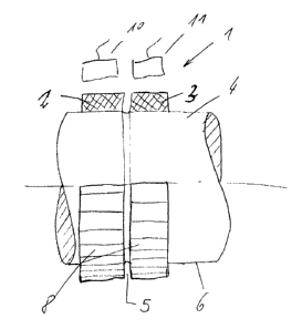
Figure 1 shows an angle-measuring device ( 1 ) consisting of a support (4)
with
two tracks (2, 3) made of a ferrite-filled plastic. The tracks (2, 3) operate
radially and are
vulcanized onto the cylindrical surface 6 of the support (4). The two tracks
(2, 3) are separated
from each other by a turned separator groove (5). Magnetic patterns (8) are
placed on the
tracks (2, 3) and sensed by the sensors ( 10, 11 ). The absolute angle
position can be determined
from the different arrangements of the patterns (8) on the two tracks (2, 3).
Figure 2 shows an angle-measuring device (1) with a support (4) and two tracks
(2, 3)
made of a ferrite-filled plastic. T'he tracks (2, 3) operate axially and are
vulcanized onto the
circular surface (7) of the support (4). The two tracks (2, 3) are separated
from each other by a
separator groove (5). Magnetic patterns (8) are placed on the tracks (2, 3)
and sensed by the
sensors ( 10, 11 ).
Figure 3 shows a support (4) onto whose cylindrical surface (6) a single track
(9) is
vulcanized. Track (9) operates radially. Track (9) consists of a ferrite-
filled plastic and forms
the base for producing several independent tracks.
Figure 4 shows the cutting in of the separator groove (S) of the track (9)
shown in
figure (3). The track (9) is completely divided, producing two tracks (2, 3),
which are
magnetized independently from each other without electromagnetic interference.
Figure 5 shows the magnetization process whereby a magnetic pattern (8) is
placed on
each of the tracks (2, 3) shown in figure 4 using a magnetization tool (12).
3