Language selection

Search

Patent 2499543 Summary

Third-party information liability

Some of the information on this Web page has been provided by external sources. The Government of Canada is not responsible for the accuracy, reliability or currency of the information supplied by external sources. Users wishing to rely upon this information should consult directly with the source of the information. Content provided by external sources is not subject to official languages, privacy and accessibility requirements.

Claims and Abstract availability

Any discrepancies in the text and image of the Claims and Abstract are due to differing posting times. Text of the Claims and Abstract are posted:

  • At the time the application is open to public inspection;
  • At the time of issue of the patent (grant).
(12) Patent: (11) CA 2499543
(54) English Title: BRAKE DRUM FINISHING & BALANCING
(54) French Title: FINITION ET EQUILIBRAGE DE TAMBOUR DE FREIN
Status: Granted and Issued
Bibliographic Data
(51) International Patent Classification (IPC):
  • F16D 65/10 (2006.01)
  • B21D 53/34 (2006.01)
  • B23B 5/00 (2006.01)
  • G01M 1/34 (2006.01)
(72) Inventors :
  • BROTHERTON, JOSEPH A. (United States of America)
  • GRIFFIN, TIMOTHY TODD (United States of America)
(73) Owners :
  • CONSOLIDATED METCO, INC.
(71) Applicants :
  • CONSOLIDATED METCO, INC. (United States of America)
(74) Agent: GOWLING WLG (CANADA) LLP
(74) Associate agent:
(45) Issued: 2010-07-27
(22) Filed Date: 2005-03-07
(41) Open to Public Inspection: 2006-09-07
Examination requested: 2005-03-07
Availability of licence: N/A
Dedicated to the Public: N/A
(25) Language of filing: English

Patent Cooperation Treaty (PCT): No

(30) Application Priority Data: None

Abstracts

English Abstract

An improved brake drum and method for machining and balancing a brake drum are provided. The inner facing surface and the outer facing surface of the brake drum are machined. The inner and outer faces of the hub end of the brake drum are also machined. The machining is accomplished in a single operation that results in a radially balanced brake drum.


French Abstract

La présente invention concerne un tambour de frein amélioré et une méthode d'usinage et d'équilibrage d'un tambour de frein. Les surfaces intérieure et extérieure du tambour de frein sont usinées. Les faces intérieure et extérieure du tambour de frein du côté du moyeu sont aussi usinées. L'usinage s'effectue en une seule opération qui permet d'obtenir un équilibrage radial du tambour de frein.

Claims

Note: Claims are shown in the official language in which they were submitted.

CLAIMS
What is claimed is:
1. A method of machining and balancing a brake drum comprising the steps of:
providing a brake drum having a generally cylindrical body having a central
radial axis and an open end and a hub end, the hub end comprising an inner
facing
surface and an outer facing surface, the brake drum body including an outer
radial
surface and an inner radial surface, the outer radial surface including a
radial edge,
holding the radial edge of the open end in a chuck assembly, machining the
inner facing surface and outer facing surface of the hub end, and machining
the outer
radial surface and inner radial surface of the brake drum body in an operation
to radially
balance the brake drum about
the central radial axis.
2. The method of claim 1
wherein the chuck assembly holds the brake drum at selected locations along
the
radial edge of the open end to allow substantially all of the outer facing
surface of the
brake drum to be machined.
3. The method of claim 2
exposing the brake drum while held in the chuck assembly to an outside radial
cutting head for machining the outer facing surface of the brake drum and an
inside
radial cutting head for machining the inner facing surface of
the brake drum.
4. The method of claim 3
exposing the brake drum while held in the chuck assembly to an inside vertical
cutting head for machining the inner facing surface of the hub end and an
outside
vertical cutting head for machining the outer facing surface of the hub end.
5. A method of machining and balancing a brake drum comprising the steps of:

providing brake drum having a generally cylindrical body having a central
radial axis and an open end and a hub end, they hub end comprising an inner
facing
surface and an outer facing surface, the brake drum body including an outer
radial
surface and an inner radial surface, holding the brake drum in a chuck
assembly,
machining the outer radial surface and inner radial surface of the brake drum
body and
machining the inner facing surface and outer facing surface of the
hub end, in an operation to balance the brake drum about the central radial
axis.
6. The method of claim 5,
wherein the brake drum outer radial surface includes an outer radial edge, and
wherein the chuck assembly holds the brake drum at selected locations along
the outer
radial edge to allow substantially all of the outer radial surface of the
brake drum to be
machined.
7. The method of claim 5, further comprising
exposing the brake drum while held in the chuck assembly to an outside radial
cutting head for machining the outer radial surface of the brake drum and to
an inside
radial cutting head for machining the inner radial surface of the brake drum.
8. The method of claim 5, further comprising
exposing the brake drum while held in the chuck assembly to an inside vertical
cutting head for machining the inner facing surface of the hub end and an
outside
vertical cutting head for machining the outer facing surface of the hub end.

Description

Note: Descriptions are shown in the official language in which they were submitted.


CA 02499543 2005-03-07
BRAKE DRUM FINISHING & BALANCING
BACKGROUND OF THE INVENTION
The present invention relates to brake drums and, in particular, to improved
finished and
balanced brake drums and a method of finishing and balancing such brake drums.
Most brake drums for trucks and similar heavy duty vehicles are comprised of a
cast iron
brake drum that is subsequently machined to near final tolerances. Typically,
the machined
brake drum has a slight imbalance that needs to be corrected. Accordingly, the
brake drum is
subjected to a balancing operation al=ter machining. Such balancing can
comprise welding
correcting weights to an outer surface of the drum or removing part of the
brake drum.
In particular, brake drums that have an integral raised squealer band
extending from near
an open end of the brake drum can be balanced by removing a portion of the
squealer band.
Such balancing by removing a portion of the squealer band to a constant or
substantially constant
depth is shown in U.S. Patent No. 5,483,855. Another method of balancing is
shown in U.S.
Patent No. 4,986,149, which discloses the removing of a crescent or wedge of
material from the
integral squealer band. It is desirable to provide a machined and balanced
brake drum, and a
method for machining and balancing such a brake drum.
SUMMARY OF THE INVENTION
It is an object of the present :invention to provide an improved machined and
balanced
brake drum.
It is another object of the present invention to provide an improved method of
machining
and balancing a brake drum.
It is another object of the present invention to provide an improved method of
machining
and balancing a brake drum by machining the inner and outer radial surfaces of
the brake drum.

CA 02499543 2005-03-07
It is another object of the present invention to provide an improved method of
machining and
25 balancing a brake drum by machining the inner and outer surfaces of the hub
end of the brake
drum.
The improved method for balancing a brake drum in accordance with the present
invention utilizes a cutting or milling machine or a lathe to machine the
inner and outer radial
surfaces of the brake drum. The inner and outer surfaces of the hub end of the
brake drum can
30 also be machined. This machining is accomplished in a single operation
while the brake drum is
held in a chuck assembly. The chuck assembly holds the brake drum at selected
points around
the outer radial edge of the open end of the brake drum. Such chuck assembly
is designed to
accurately hold the brake drum during machining to avoid eccentricity in the
brake drum as it is
rotated in the chuck assembly and e~;posed in the outer heads. Further, the
brake drum is held in
3~ the chuck assembly in a manner that allows almost all of the outer radial
surface of the brake
drum to be machined. The result of the machining is to produce a brake drum
that is balanced
radially about the central radial axis of the brake drum.
BRIEF DESCRIPTION OF THE DRAWINGS
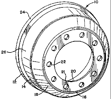
Figure 1 is a perspective view of a brake drum in accordance with the present
invention;
40 Figure 2 is an end view of the hub end of a brake drum in accordance with
the present
invention;
Figure 3 is a perspective view of the open end of a brake drum in accordance
with the
present invention;
Figure 4 is an end view of the open end of a brake drum in accordance with the
present
45 invention;

CA 02499543 2005-03-07
Figure 5 is a perspective view of a brake drum held in a chuck assembly in
accordance
with the present invention;
Figure 6 is a partial detailed side view of a brake drum held in a chuck
assembly in
accordance with the present invention;
50 Figure 7 is a perspective view in partial cross section of a brake drum
held in a chuck
assembly with cutting heads also shown.
DETAILED DESCRIPTION OF THE PREFERRED EMBODIMENT
Referring to Figures 1-4 of the drawings, a brake drum in accordance with an
55 embodiment of the present invention is shown generally at 10. It is seen
that brake drum 10 is a
generally cylindrical structure, having a circular open end 12 and a generally
cylindrical braking
section 14 extending from open end 12 to hub end 16. Hub end 16 is seen to
comprise a
generally flat outer surface 21 and firmer surface 23 that terminates by
forming circular hub
opening 20. A plurality of wheel 1u1; openings 22 are spaced around outer
surface 21 of hub end
60 16.
Transition section 18 is seen to extend from braking section 14 to outer
surface 21 of hub
end 16. Braking section 14 itself is ;~ generally cylindrical section
extending at a nearly normal
relation to open end 12. However, it is also understood that a preferred
embodiment of the
present invention could have the outer surface 26 of braking section 14
extending at a slightly
65 less than normal angle to open end 12.
It should be understood that brake drum 10 is typically made of cast iron in a
foundry
operation. Accordingly, finishing machining operations are necessary. Such
machining would
include the finishing of an inner surface 25 of braking section 14 to assure a
nearly perfect inner

CA 02499543 2005-03-07
cylindrical surface. Such surfaces are necessary to accommodate the brake pads
from the
70 braking structure that brake drum 10 would surround.
Referring to Figures 5 and 6, unfinished brake drum 31 is shown to be a
generally
cylindrical structure. Brake drum 31 is usually made of iron in a foundry
casting operation.
Accordingly, outer facing surface 41 of hub end 42, and outer radial surface
44 of brake drum 31
are shown to have an unfinished, as cast surface. Transition area 46 between
hub end 42 and
75 outer radial surface 44 is also shown to have an unfinished, as cast
surface. Open end 37 of
brake drum 31 faces downwardly.
It is understood that an inner facing surface (not shown) of hub end 42 also
has an
unfinished, as cast surface. Further, an inner radial surface (not shown) of
brake drum 31 also
has an unfinished, as cast surface.
80 Chuck assembly 30 is seen to comprise a cylindrical base section 33. A
plurality, usually
four, of set up posts 32 are radially adjustably positioned in set-up post
supports 52 which are
themselves affixed to base section 3:3. Set up posts 32 assist in the
radically centered positioning
of brake drum 3 I on base section 33. This assures that brake drum 31 is
radially centered for
concentric machining.
85 A plurality, usually four, of jaw clamps 34 are providing to grasp and hold
brake drum 31
on base section 33. Each jaw clamp 34 itself is held in a jaw clamp support 54
which is affixed
to base section 33. Such jaw clamp 34 is seen to be able to rotate through an
arc in order to
contact and hold brake drum 31 on base section 33. Note that the contact
between jaw clamp 34
and brake drum 31 is at preselected locations about radial edge 35 of an open
end 37 of brake
90 drum 31. It is seen that the preselected contact locations are rather
inobtrusive and leave almost
all of the outer radial surface 44 of brake drum 31 open to machining by a
cutting head.
~4~

CA 02499543 2005-03-07
Referring now to Figure 7, brake drum 31 is seen to also include inner facing
surface 43
of hub end 42, inner radial surface 45 and inner transition surface 47 between
inner facing
surface 43 of hub end 42 and inner radial surface 45. Lug openings 57 are also
shown in hub end
95 42.
Outer hub cutting head holder 62 is seen to support cutting head arm 64 and
cutting head
edge 66. It can be seen that as brake; drum 31 is rotated about its radial
center axis 61 while held
in chuck assembly 30, outer hub cutting head holder 62 can be programmed to
have cutting head
edge 66 contact and machine the entire outer facing surface 41 of hub end 42.
100 Inner hub cutting head holder 72 is seen to support cutting head arm 74
and cutting head
edge 76. It can be seen that as brake drum 31 is rotated about its radial
center axis 61 while held
in chuck assembly 30, inner hub cutting head holder 72 can be programmed to
have inner hub
cutting head edge 76 contact and machine the entire inner facing surface 43 of
hub end 42.
Outer radial cutting head holder 82 is seen to support cutting head arm 84 and
cutting
105 head edge 86. It can be seen that as brake drum 31 is rotated about its
radial center axis 61 while
held in chuck assembly 30, outer radial cutting head edge 86 contact and
machine virtually the
entire outer radial surface 44 and outer transition section surface 46 of
brake drum 31. Only the
small area from open end 37 to the bottom 87 of the outer radial surface 44 is
not machined in
this operation due to the need for jaw clamp 34 to contact brake drum 31 at
preselected locations
110 35.
Inner radial surface cutting head holder 92 is seen to support cutting head
arm 94 and
cutting head edge 96. It can be seen that as brake drum 31 is rotated about
its radial center axis
61 while held in chuck assembly 30, inner radial cutting head holder 92 can be
programmed to
~.. 5 ...

CA 02499543 2005-03-07
have inner radial cutting edge 96 contact and machine the entire inner radial
surface 45 and inner
1 1 ~ transition surface 47.
Accordingly, it is seen how t>rake drum 31 is machined and balanced in a
single operation
while held in chuck assembly 30.
... 6 ...

Representative Drawing
A single figure which represents the drawing illustrating the invention.
Administrative Status

2024-08-01:As part of the Next Generation Patents (NGP) transition, the Canadian Patents Database (CPD) now contains a more detailed Event History, which replicates the Event Log of our new back-office solution.

Please note that "Inactive:" events refers to events no longer in use in our new back-office solution.

For a clearer understanding of the status of the application/patent presented on this page, the site Disclaimer , as well as the definitions for Patent , Event History , Maintenance Fee  and Payment History  should be consulted.

Event History

Description Date
Common Representative Appointed 2019-10-30
Change of Address or Method of Correspondence Request Received 2018-01-16
Grant by Issuance 2010-07-27
Inactive: Cover page published 2010-07-26
Revocation of Agent Requirements Determined Compliant 2010-06-28
Inactive: Office letter 2010-06-28
Appointment of Agent Requirements Determined Compliant 2010-06-28
Pre-grant 2010-05-07
Inactive: Final fee received 2010-05-07
Notice of Allowance is Issued 2010-04-19
Letter Sent 2010-04-19
Notice of Allowance is Issued 2010-04-19
Inactive: Approved for allowance (AFA) 2010-04-07
Amendment Received - Voluntary Amendment 2010-01-14
Inactive: S.30(2) Rules - Examiner requisition 2009-08-07
Amendment Received - Voluntary Amendment 2009-05-13
Inactive: S.30(2) Rules - Examiner requisition 2009-01-05
Amendment Received - Voluntary Amendment 2008-07-23
Inactive: S.30(2) Rules - Examiner requisition 2008-04-24
Amendment Received - Voluntary Amendment 2008-01-24
Inactive: S.30(2) Rules - Examiner requisition 2007-09-14
Application Published (Open to Public Inspection) 2006-09-07
Inactive: Cover page published 2006-09-06
Inactive: IPC assigned 2005-06-06
Inactive: First IPC assigned 2005-06-06
Inactive: IPC assigned 2005-06-03
Inactive: Inventor deleted 2005-04-11
Filing Requirements Determined Compliant 2005-04-11
Letter Sent 2005-04-11
Inactive: Filing certificate - No RFE (English) 2005-04-11
Inactive: Applicant deleted 2005-04-11
Application Received - Regular National 2005-04-11
Request for Examination Requirements Determined Compliant 2005-03-07
All Requirements for Examination Determined Compliant 2005-03-07

Abandonment History

There is no abandonment history.

Maintenance Fee

The last payment was received on 2010-03-03

Note : If the full payment has not been received on or before the date indicated, a further fee may be required which may be one of the following

  • the reinstatement fee;
  • the late payment fee; or
  • additional fee to reverse deemed expiry.

Please refer to the CIPO Patent Fees web page to see all current fee amounts.

Owners on Record

Note: Records showing the ownership history in alphabetical order.

Current Owners on Record
CONSOLIDATED METCO, INC.
Past Owners on Record
JOSEPH A. BROTHERTON
TIMOTHY TODD GRIFFIN
Past Owners that do not appear in the "Owners on Record" listing will appear in other documentation within the application.
Documents

To view selected files, please enter reCAPTCHA code :


To view images, click a link in the Document Description column. To download the documents, select one or more checkboxes in the first column and then click the "Download Selected in PDF format (Zip Archive)" or the "Download Selected as Single PDF" button.

List of published and non-published patent-specific documents on the CPD .

If you have any difficulty accessing content, you can call the Client Service Centre at 1-866-997-1936 or send them an e-mail at CIPO Client Service Centre.


Document
Description 
Date
(yyyy-mm-dd) 
Number of pages   Size of Image (KB) 
Description 2005-03-07 6 205
Claims 2005-03-07 3 88
Abstract 2005-03-07 1 10
Drawings 2005-03-07 4 128
Representative drawing 2006-08-10 1 17
Cover Page 2006-08-17 1 41
Claims 2008-01-24 3 71
Claims 2009-05-13 3 87
Claims 2010-01-14 2 79
Representative drawing 2010-07-12 1 19
Cover Page 2010-07-12 1 44
Maintenance fee payment 2024-02-20 49 2,031
Acknowledgement of Request for Examination 2005-04-11 1 178
Courtesy - Certificate of registration (related document(s)) 2005-04-11 1 105
Filing Certificate (English) 2005-04-11 1 158
Reminder of maintenance fee due 2006-11-08 1 112
Commissioner's Notice - Application Found Allowable 2010-04-19 1 166
Fees 2009-03-06 1 46
Fees 2010-03-03 1 39
Correspondence 2010-05-07 2 52
Correspondence 2010-06-28 1 14
Correspondence 2010-06-10 9 351