Note: Descriptions are shown in the official language in which they were submitted.
CA 02499671 2005-03-21
WO 2004/032815 PCT/US2003/024275
MEDICAL EXAMINATION TABLE
Field of the Invention
This invention relates generally to medical examination tables
and, more particularly, to a medical examination table which is vertically
movable between a lowered patient entry/exit position and a raised patient
examination position via a motorized lift assembly.
Background of the Invention
Medical examination tables are known to have a patient-
supporting surface comprising a seat portion and an adjustable backrest
portion. The backrest portion is movable between a horizontal position and
an inclined position so that a patient is supported in an upright position
during certain examination procedures. Motorized lift assemblies have been
used with examination tables to vertically raise and lower the entire patient
supporting surface of the table so that in a lowered position, a patient can
enter or exit the examination table. The examination table can be vertically
CA 02499671 2005-03-21
WO 2004/032815 PCT/US2003/024275
raised by the lift assembly to a height suitable for a particular medical
examination or procedure.
One drawback with known medical examination tables is that
the table's patient-supporting surface is spaced a significant distance above
the floor even when the table is lowered to its lowest patient entry/exit
position. When the patient supporting surface is spaced a significant
distance above the floor, small children, elderly patients or disabled
patients
often require assistance in order to get on top of the supporting surface
before the supporting surface is raised for the examination. Sometimes
more than one assistant is required to lift a patient from a wheelchair to the
patient supporting surface on top of the medical examination table even
when the examination table is lowered to its lowest position.
Another drawback encountered with known medical
examination tables is that the examination table lacks a surface on which
the physician may conveniently place medical instruments needed during an
examination. Typically, the examining physician must have an assistant
hold a tray with all the instruments needed during an examination or the
instruments are placed on a table located near the examination table. The
instrument supporting table takes up valuable space in the examination
room and may be accidentally jarred by the physician or assistant so that
the instruments may become contaminated and/or difficult for the physician
to reach when the instruments are needed.
Another drawback with known medical examination tables is
that the examination tables lack sufficient storage space for rolls of paper
- 2 -
CA 02499671 2005-03-21
WO 2004/032815 PCT/US2003/024275
towels and other bulky items required for the examination or for clean-up of
the examination area. Such bulky items are typically stored in cabinets in
the examination room but that storage space is generally limited.
Therefore, there is a need for a medical examination table that
improves patient entry or exit while providing comfort to the patient during
movement of the medical examination table between entry/exit and
examination and treatment positions. There is also a need for a medical
examination table that improves a physician's access to medical
instruments and other items needed during an examination. There is yet
also a need for an examination table that improves storage of bulky items
required for the examination and clean-up of the examination area.
Summary of the Invention
The present invention overcomes the foregoing and other
shortcomings and drawbacks of medical examination tables heretofore
known. While the invention will be described in connection with certain
embodiments, it will be understood that the invention is not limited to these
embodiments. On the contrary, the invention includes all alternatives,
modifications and equivalents as may be included within the spirit and
scope of the present invention.
The present invention comprises a medical examination table
which is movable between a lowered patient entry/exit position and a raised
patient examination position. The medical examination table of the present
invention has three principal components: a base, a table assembly located
- 3 -
CA 02499671 2005-03-21
WO 2004/032815
PCT/US2003/024275
above the base and a scissor-lift assembly which functions to raise and
lower the table assembly relative to the base. The motorized scissor-lift
assembly includes a motorized drive assembly and a scissor mechanism
extending between the base and the table assembly.
The table assembly includes a generally rectangular upper
frame, a seat assembly secured to the upper frame at a front thereof, and a
backrest assembly secured to the upper frame at a rear end thereof. The
backrest assembly includes a backrest support movable between a
horizontal position and an inclined position to enable a patient to sit up
while being examined. A backrest is secured to the backrest support and a
seat is secured to the seat assembly. The upper surfaces of the backrest
and seat provide a patient support surface which supports the patient for
examination purposes.
In accordance with one aspect of the present invention, the
1 5 backrest assembly includes a storage pocket adapted to house medical
equipment and supplies, such as rolls of paper towels and other bulky
items. The storage pocket and its contents are concealed when the
backrest support and attached backrest are in their lowered position. When
the backrest support and backrest attached thereto are raised, the contents
of the storage pocket are easily accessed.
In accordance with another aspect of the present invention,
the seat assembly includes a pull-out drawer which defines a storage area
for medical instruments and other necessary accessories. The pull-out
drawer has a front panel which is pivotally mounted to the drawer. The
- 4 -
CA 02499671 2005-03-21
WO 2004/032815 PCT/US2003/024275
front panel is pivoted between a vertical position lying generally parallel to
a
front wall of the drawer and a generally horizontal position lying generally
transverse to the front wall of the drawer. In its lowered or downward
position, the front panel may be used as a tray to support medical
instruments or other items required by a physician during an examination.
When the front cover is pivoted downwardly into a generally horizontal
position, it may function as a rest or support for medical instruments being
used for purposes of the examination.
In accordance with yet another aspect of the present
invention, a scissor-life assembly extends between the base and the upper
frame of the table assembly. This scissor-lift assembly comprises two sets
of legs, with the first set of legs being pivotally secured to the second set
of legs. The first set of legs has forward ends which are pivotally secured
to the base at fixed locations at the front of the base. These legs extend
upwardly and have rear ends to which non-rotatable bearings are attached.
The bearings are adapted to move in horizontally oriented slides which are
fixed to the inside surfaces of the upper frame of the table assembly.
Likewise, each of the second set of legs have forward ends pivotally
secured at fixed locations to the front of the upper frame. The rear ends of
each of the second set of legs have similar non-rotatable bearings attached
thereto which are adapted to move in horizontally oriented slides which are
fixed to inside surfaces of the base. When the table assembly is raised and
lowered, the bearings slide inside the slides in a horizontal manner thereby
- 5 -
CA 02499671 2005-03-21
WO 2004/032815 PCT/US2003/024275
causing the legs to move and the table assembly to raise or lower relative
to the base.
A motorized drive assembly is used to move the table
assembly upwardly and downwardly relative to the base. The drive
assembly comprises a pivotal motor having a horizontally oriented output
shaft connected to a gear box. The output shaft of the motor drives an
actuator through the gear box. A lower end of the actuator is pivotally
secured to the base and is operatively coupled to the motor which functions
to rotate the actuator which is a threaded ball screw in one embodiment of
the present invention. The actuator is threadably engaged with a nut and a
block mounted to the nut so that rotation of the actuator causes the nut
and block to travel along the length of the actuator. The block is secured to
one of the sets of legs so that movement of the block by the actuator
causes the table assembly to move upwardly or downwardly relative to the
base.
When the table assembly is lowered, the bearings secured to
the first and second sets of legs move rearwardly inside the slides attached
to the base and upper frame of the table assembly. As the examination
table is lowered, the actuator and its associated drive motor pivot
downwardly so that the actuator and drive motor nest within an internal
cavity defined by the base. In its lowermost patient entry/exit position, the
patient support surface is located approximately eighteen (18) inches above
the ground to provide a convenient and safe entry and exit position for the
patient. In its uppermost position, the patient support surface is located
- 6 -
CA 02499671 2005-03-21
WO 2004/032815 PCT/US2003/024275
approximately thirty-seven (37) inches above the ground to provide a
convenient examination position of the patient for the physician.
These and other objects and advantages of the present
invention will be more readily apparent from the following drawings.
Brief Description of the Drawings
The accompanying drawings, which are incorporated in and
constitute a part of this specification, illustrate embodiments of the
invention and, together with a general description of the invention given
above, and the detailed description of the embodiments given below, serve
to explain the principles of the invention.
FIG. 1 is a perspective view of a medical examination table in
accordance with the principles of the present invention, shown in a raised
patient examination position.
FIG. lA is a perspective view similar to FIG. 1 illustrating the
medical examination table in a lowered patient entry/exit position with the
backrest slightly inclined.
FIG. 2 is perspective view of the interior of the medical
examination table with the collapsible shroud assembly, seat cushion and
back rest cushion removed.
FIG. 2A is a perspective view similar to FIG. 2 illustrating the
medical examination table in its lowered patient entry/exit position with the
collapsible shroud assembly, seat cushion and back rest cushion removed.
- 7 -
CA 02499671 2005-03-21
WO 2004/032815 PCT/US2003/024275
FIG. 3 is a perspective view of a pull-out drawer of the present
invention having a front panel pivotally mounted thereto.
FIG. 4 is a perspective view of the shroud assembly of the
present invention.
FIG. 5 is a partially disassembled view of a portion of the
scissor-lift assembly of the present invention.
FIG. 6 is a partially disassembled view of another portion of
the scissor-lift assembly of the present invention and a base of the medical
examination table.
FIG. 7 is a perspective view of a scissor-lift leg slide of the
present invention.
FIG. 7A is a cross-sectional view taken along the line 7A-7A of
FIG. 7.
FIG. 8 is a perspective view of a scissor-lift leg bearing of the
1 5 present invention.
Detailed Description of the Drawings
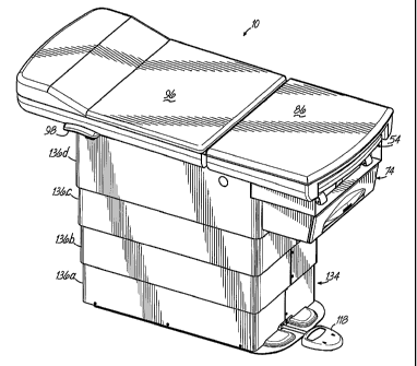
Referring to the drawings, and to FIGS. 1 and lA in particular,
a medical examination table 10 in accordance with the principles of the
present invention is vertically movable between a raised patient examination
position, illustrated in FIG. 1, and a lowered patient entry/exit position
illustrated in FIG.1A. In its lowered position as shown in FIG. 1A, a child,
elderly patient or disabled patient may be easily transported onto the table
prior to the table being raised as shown in FIG. 1 for examination purposes.
- 8 -
CA 02499671 2005-03-21
WO 2004/032815 PCT/US2003/024275
When the examination is over, the table may be lowered so that the patient
may be easily and safely moved from the table to a wheelchair or other
appropriate location.
As best illustrated in FIGS. 2 and 2A, the medical examination
table comprises a base 12, a table assembly 14 located above the base 12,
and a scissor-lift assembly 16 connected to and extending between the
base 12 and the table assembly 14. The operation of the scissor-lift
assembly 16 will be described in greater detail below.
The base 12 has an internal cavity 18 defined by a pair of side
members 19, a rear member 20, a front member 22 and a base bottom 24.
A pair of slides 26 are mounted to the side members 19 of the base 12
and are exposed through the inside surfaces 28 of the side members 19.
The details of each slide 26 and its operation is described in greater detail
below. Each of the slides 26 is adapted to receive and retain a non-rotatable
bearing 30 (see FIGS. 5 and 8) which is part of the scissor-lift assembly 16.
The table assembly 14 of the present invention is best
illustrated in FIGS. 2 , 2A and 5. Referring to FIG. 5, the table assembly 14
comprises an upper frame 32 which is generally rectangular in shape. The
upper frame 32 comprises two side frame members 34, a rear frame
member 36 secured to the side frame members 34 and extending
therebetween, and a front pivot bar 38 which passes through collars 40
located in the side frame members 34. Secured to each of the side frame
members 34 is a slide 26 which is exposed through the inside surface 42 of
each side frame member 34. Slides 26 are adapted to receive and retain
- 9 -
CA 02499671 2005-03-21
WO 2004/032815 PCT/US2003/024275
the non-rotatable bearings 30 of the scissor-lift assembly 16 as described in
detail below.
Referring to FIGS. 2 and 2A, the table assembly 14 further
comprises a seat assembly 50 secured to the upper frame 32 at the front
thereof. The seat assembly 50 includes a housing 52 which supports a
pull-out fluid collection pan 54. The pull-out fluid collection pan 54 is
movable between a closed position, illustrated in FIG. 2A, and an extended
position illustrated in phantom in FIG. 2. The pull-out fluid collection pan
54 has a centrally located recess or well 56 adapted to house and store
fluids resulting from an examination occurring on the table 10. In order to
pull out the collection pan 54, a physician grasps a front lip 58 of the
collection pan 54 and pulls in the direction of arrow 60 until the collection
pan 54 has been fully extended. The collection pan 54 may then be pushed
inwardly to its closed position once it has been used and adequately
cleaned.
In accordance with one aspect of the present invention, the
seat assembly 50 includes a pull out drawer assembly 61, illustrated in
detail in FIG. 3. The drawer assembly 61 comprises a drawer housing 62
having an interior 63 defined by a housing bottom 64, a rear wall 65 and
side walls 66 having inner surfaces 67 to which are secured tracks 68.
Slide members 69 are mounted to slide inside the tracks 68 in a
conventional manner. Each slide member 69 comprises a first section 70
and a second section 71 adapted to move inside the first section 70.
Securing brackets 72 (only one being shown) are secured to the second
- 10-
CA 02499671 2005-03-21
WO 2004/032815 PCT/US2003/024275
sections 71 of the slide members 69. Each of the securing brackets 72 has
a series of spaces slots 73 integrally formed therein.
A drawer 74 having an interior 75 for the storage of medical
instruments and any other necessary accessories, is adapted to be
removably secured to the securing brackets 72. The drawer's storage
interior 75 is defined by a drawer bottom 76, a back wall 77, side walls 78,
and a front wall 79 having a cutout 80 formed therein. A front panel 81 is
hingedly secured to the front wall 79 of the drawer 74 in a manner
described in greater detail below so that the front panel 81 is pivotal
between a vertical position lying generally parallel to the front wall 79 of
the drawer 74, and a horizontal position lying generally traverse to the front
wall of the drawer 74 as shown in FIG. 5. The side walls 78 of the drawer
74 have a series of spaced ribs 82 adapted to be received in the slots 73 of
the securing brackets 72. Thus, the drawer 74 may be lowered into a fixed
position between the securing brackets 72, with the ribs 82 of the drawer
74 being engaged in the slots 73 of the securing brackets 72. When the
drawer needs to be cleaned, it may be lifted vertically, with the ribs 82 of
the drawer 74 being disengaged from the slots 73 of the securing brackets
72.
In a conventional manner, the drawer 74 may be pulled
outwardly from a closed position illustrated in FIG. 2 to an extended
position illustrated in phantom in FIG. 2A by a physician grasping a handle
5, shown in FIG. 2A, located on the front side of the front panel 81 of the
drawer 74. The front panel 81 is hingedly mounted to the front wall 79 of
-11-
CA 02499671 2005-03-21
WO 2004/032815 PCT/US2003/024275
the drawer 74 about a pin 85 which defines a horizontally-oriented pivot
axis Al about which the front panel 81 may rotate. More particularly, the
front panel 81 has a circular hinge portion 83 which rotates through an
opening 84 formed in the front wall 79 of the drawer 74. The front panel
81 of the drawer 74 is movable between an upward or raised position
shown in FIG. 2A, in which it covers the cutout 80 formed in the drawer's
front wall 79, to a downward or lowered position, illustrated in FIG. 3, in
which the front panel 81 may be used as a tray to support medical
instruments (not shown) or other items required by a physician during an
examination procedure. The inside surface 6 of the front panel 81 has a
depression 7 formed therein which aids in preventing the medical
instruments (not shown) from falling off the front panel 81 when the front
panel 81 is used as an instrument support tray, as shown in FIG. 3.
Further referring to FIG. 3, the hinge portion 83 of the front
panel 81 includes a pair of resilient latches 84 that engage an inner surface
of the front wall 79 of the drawer 74 when the front panel 81 is folded to
its downward or lowered position. For safety purposes, the latches 84 are
designed to disengage from the front wall 79 when a load of approximately
ten (10) pounds is exerted downwardly on the front panel 81 so that the
front panel 81 collapses downwardly. In this way, the latches 84 prevent
the front panel 81 from being damaged in the event the front panel 81 is
overloaded or stepped upon. The front panel 81 is returned to its operative
position simply by reengaging the latches 84 with the front wall 79 of the
drawer 74.
- 1 2 -
CA 02499671 2005-03-21
WO 2004/032815 PCT/US2003/024275
Referring to FIGS. 2 and 2A, another component of the seat
assembly 50 of the present invention is a mounting bracket 85, which is
secured to the housing 52 of the seat assembly 50. A seat 86, illustrated
in FIGS. 1 and 1A, is secured to the mounting bracket 85 in conventional
fashion; however, the seat 86 may be secured using other mechanisms as
well without departing from the spirit of the present invention.
The table assembly 14 further comprises a backrest assembly
87, which includes a housing 88, seen best in FIGS. 2 and 2A. The
backrest assembly 87 further comprises a backrest support 92, including a
backrest support bracket 94 to which is secured a backrest 96. The
backrest support 92 and accompanying backrest 96 are movable between a
horizontal or lowered position, illustrated in FIGS. 1 and 2, and an inclined
position, illustrated in FIGS. lA and 2A. In order to raise the backrest 96, a
physician simply grabs the handles 98, best illustrated in FIGS. 2 and 2A,
and lifts upwardly. The backrest 96 may be locked in numerous positions
using any know technology.
In accordance with another aspect of the present invention, a
storage pocket 90 is centrally located in the housing 88 and is adapted to
house medical equipment and supplies, including, but not limited to, rolls of
paper towels and other medical instruments and cleaning supplies. In this
way, the storage pocket 90 and its contents are concealed when the
backrest 96 is in its lowered position. The contents of the storage pocket
90 are easily accessed by raising of the backrest 96.
-13-
CA 02499671 2005-03-21
WO 2004/032815 PCT/US2003/024275
The scissor-lift assembly 16 of the present invention is best
illustrated in FIGS. 5 and 6. The scissor-lift assembly 16 is secured to the
upper frame 32 of the table assembly 14 and the base 16. The scissor-lift
assembly 16 comprises a first set 100 of legs 102. Each of the legs 102 is
pivotally secured at lower ends thereof to the base 12 about a horizontal
axis A2, illustrated in FIG. 5. Tubes 104 extending outwardly from the
lower ends of the legs 102 are received in the side members 19 of the base
at a fixed location (see FIG. 2.). At the upper opposite ends of the legs
102 is a shaft 106 extending therebetween to which are secured the non-
rotatable bearings 30 outside of the legs 102. The bearings 30 are received
inside the slides 26 secured to the upper frame 32 and slide therein.
A second set 108 of legs 110 are fixedly secured to the side
frame members 34 of the upper frame 32 via the front pivot bar 38. The
front pivot bar 38 defines another horizontal pivot axis A3 (see FIG. 5).
Additional non-rotatable bearings 30 are attached to the outer ends of a
shaft 107 extending between the lower ends of the legs 110. The bearings
30 (only one being shown) attached to the shaft 107 are adapted to slide
inside the slides 26 attached to the side members 19 of the base 12 (see
FIG. 2.). The first set 100 of legs 102 and the second set 108 of legs 110
are pivotally connected together generally at a midpoint of the legs 102 and
110 with a shaft 112 which defines another horizontal pivot axis A4 (see
FIG. 5).
FIG. 6 illustrates a drive assembly 114 of the present invention
which forms part of the scissor-lift assembly 16. The drive assembly 114
-14-
CA 02499671 2005-03-21
WO 2004/032815 PCT/US2003/024275
comprises a pivotal motor 115 having a horizontally oriented output shaft
116 (FIG. 2) connected to a gear box 117. The motor 115 is operated by a
foot pedal 118 located at the front of the base 12. Activation of the motor
115 by the foot pedal 118 rotates the motor output shaft 116 which drives
an actuator 122 through the gear box 117. In one embodiment, actuator
122 is a threaded ball screw but may assume other configurations as well
without departing from the spirit and scope of the present invention. The
lower end of the actuator 122 is pivotally mounted to a bracket 133 (FIG.
6) mounted to the base 12. The foot pedal 118 is electrically coupled to a
control box 119 located in the base cavity 18 (see FIG. 2). A nut 126 (FIG.
6) is threaded to the ball screw actuator 122 so that the nut 126 and a
block 124 mounted to the nut 126 are driven by the actuator 122 between
raised and lowered positions. The block 124 has a pair of passageways
128 therethrough which are adapted to receive shafts 130 of the scissor-lift
assembly 16 as shown in FIG. 5 so that the block 124 is secured to the
second set 100 of legs 102.
FIGS. 7 and 7A illustrate one of the slides 26 of the present
invention. Each slide 26 has a web portion 142, an upper flange portion
144 and a lower flange portion 146. The upper and lower flange portions
144, 146 each have an inside surface 144a and 146b, respectively, which
are parallel to one another. The web portion 142 has an inside surface
142a. The inside surfaces 144a, 146b and 142a define a track 44 of the
slide 26 inside which rides one of the non-rotatable bearings 30. The slides
26 are preferably made of aluminum but may be made of any material.
-15-
CA 02499671 2005-03-21
WO 2004/032815 PCT/US2003/024275
FIG. 8 illustrates one of the non-rotatable bearings 30. Each of
the bearings 30 has a circular recess 148 adapted to receive and retain one
end of one of the shafts 106, 107. Each bearing 30 has a rectangular
outer portion 150 having outer surfaces 152. The two opposed upper and
lower outer surfaces 152 define a height distance which is approximately
equal to the height distance between the inside surfaces 144A and 146A of
the upper and lower flange portions 144, 146 of each slide 26. Thus, each
bearing 30 is able to travel inside the track 44 of the slide 26 in a non-
rotatable manner, and the approximately equal height of the bearings 30
and the inside height of the tracks 44 creates a very tight clearance to
accommodate the tension and compression forces exerted by the legs 102
and 110. The bearings 30 are made of plastic, in particular, Polymer Blend
15, a plastic commercially available from Performance Plastics,
Incorporated, 435 Brownway Avenue, Cincinnati, Ohio 45209.
In operation, when the foot pedal 118 is depressed to lower
the examination table 10, the motor 116 is actuated causing the actuator
122 to rotate. Thus, the nut 126 and block 124 are driven downwardly,
causing the bearings 30 to ride rearwardly inside the slides 26 attached
along the actuator 122 to the base 12 and upper frame 32, and the upper
frame 32 to move downwardly until it rests upon an upper surface 123 of
the side members 19 of the base 12. At this point, the upper frame 32
actuates switches 132 (FIG. 6) stopping the motor. As the examination
table 10 is lowered, the actuator 122 and its associated drive motor 115
pivot downwardly about the pivotal connection of the actuator 122 to the
-16-
-
CA 02499671 2005-03-21
WO 2004/032815 PCT/US2003/024275
bracket 133. The actuator 122 and motor 115 rest within the internal
cavity 18 of the base 12 when the examination table 10 is moved to the
patient entry/exit position shown in FIGS. 1A and 2A. In its lowermost
position, the patient support surface is located approximately eighteen (18)
inches above the ground to provide a convenient and safe entry and exit
position for the patient.
To raise the table assembly 14, the foot pedal 118 is
depressed to actuate the motor 115. This causes the actuator 122 to
rotate in the opposite direction, thereby moving the nut 126 and block 124
upwardly and causing the bearings 30 to move forwardly in the slides 26.
Eventually the nut 126 and block 124 will not go any higher on the actuator
122, at which point the motor 115 is stopped. As the examination table
10 is raised to a patient examination position, the actuator 122 and motor
115 pivot upwardly as shown in FIG. 2. In its uppermost position, the
patient support surface is located approximately thirty-seven (37) inches
above the ground to provide a convenient examination position of the
patient for the physician.
As best illustrated in FIGS. 1 and 4, the scissor-lift assembly
16 is covered by a shroud assembly 134, comprising multiple shroud pieces
136A-D, each being nestable inside the shroud piece directly above it.
Although four shroud pieces are illustrated and described, any number of
shroud pieces may be used in accordance with the present invention.
Shroud piece 136a is fixedly secured to the base 12 and shroud piece 136d
is fixedly secured to the upper frame 32. The middle shroud pieces 136b,
- 17-
CA 02499671 2012-02-14
136c float between the upper and lower shroud pieces 136d and 136a,
respectively.
Each of the shroud pieces has at least one bearing strip 138
(FIG. 4), such as a VELCRO strip, which facilitates movement of the shroud
pieces relative to one another. In addition, each of the shroud pieces
136a-d has joint 140. The joints 140 of adjacent shroud pieces are offset
relative to each other so as to not interfere with the movement and
nestability of the shroud piece 136 and of the shroud assembly 134.
The scope of the claims should not be limited by the preferred
embodiments set forth in the examples, but should be given the broadest
interpretation consistent with the description as a whole.
- 18-