Language selection

Search

Patent 2499865 Summary

Third-party information liability

Some of the information on this Web page has been provided by external sources. The Government of Canada is not responsible for the accuracy, reliability or currency of the information supplied by external sources. Users wishing to rely upon this information should consult directly with the source of the information. Content provided by external sources is not subject to official languages, privacy and accessibility requirements.

Claims and Abstract availability

Any discrepancies in the text and image of the Claims and Abstract are due to differing posting times. Text of the Claims and Abstract are posted:

  • At the time the application is open to public inspection;
  • At the time of issue of the patent (grant).
(12) Patent: (11) CA 2499865
(54) English Title: IMPROVED RECUPERATOR OF FLUE GAS HEAT
(54) French Title: RECUPERATEUR AMELIORE DE CHALEUR DES GAZ DE COMBUSTION
Status: Deemed expired
Bibliographic Data
(51) International Patent Classification (IPC):
  • F28D 7/10 (2006.01)
  • F23J 13/00 (2006.01)
  • F23J 13/02 (2006.01)
(72) Inventors :
  • RYBAK, MILAN (Canada)
(73) Owners :
  • RYBAK, MILAN (Canada)
(71) Applicants :
  • RYBAK, MILAN (Canada)
(74) Agent:
(74) Associate agent:
(45) Issued: 2012-06-12
(22) Filed Date: 2005-03-24
(41) Open to Public Inspection: 2006-09-24
Examination requested: 2008-12-31
Availability of licence: N/A
(25) Language of filing: English

Patent Cooperation Treaty (PCT): No

(30) Application Priority Data: None

Abstracts

English Abstract

The present invention relates to flue-mounted power heat recuperators designed to transfer heat from flue gas through metal to air. In this invention a heat reflecting flexible sleeve encloses a metal flue of low emissivity, forming a "tube-within-a-tube" heat exchanger, and heat is reclaimed directly from the outside surface of the said flue by means of counterflow or parallel-flow forced air convection. The above arrangement provides air of higher temperature, and when combined with a central home-heating forced air furnace it increases temperature of supply air and enhances efficiency of the whole central home-heating system.


French Abstract

La présente invention concerne des récupérateurs de chaleur montés sur une cheminée et conçus pour transférer la chaleur de gaz de combustion à travers le métal et vers l'air. Dans la présente invention, un manchon flexible réfléchissant la chaleur enferme un conduit de cheminée en métal à faible émissivité, formant un échangeur de chaleur « tube à l'intérieur d'un tube », et la chaleur est récupérée directement de la surface extérieure de ladite cheminée au moyen de la convection à air pulsé d'écoulement en parallèle ou à contre-courant. L'arrangement susmentionné fournit de l'air à température supérieure et, s'il est combiné à une installation de chauffage central, il augmente la température de l'air soufflé et augmente l'efficacité de l'entière installation de chauffage central.

Claims

Note: Claims are shown in the official language in which they were submitted.


CLAIMS

1. A system for transferring heat from flue gas through
metal to air to achieve maximum surface temperature and bring
a higher rate of surface to air convective heat transfer,
comprising:

a metal flue for venting flue gas from a combustion
heater, stove or furnace, wherein said metal flue has outside
surface of low emmissivity;

spacing means arranged on periphery of said metal
flue wherein said spacing means have no areal contact with
said metal flue;

a flexible sleeve having a wall made of a heat reflecting
material and inside diameter sized to fit over said spacing
means wherein said flexible sleeve is held in coaxial position
to said metal flue by said spacing means thereby forming an
annular passageway along said metal flue to allow air flow
along and in contact with outside surface of said metal

flue;

an outlet air duct fluidly connected to said flexible
sleeve; and

a fan or other means generating negative pressure in the
said outlet air duct.

2. The system of claim 1 wherein said furnace is a central
home-heating forced air furnace and said outlet air duct is
fluidly connected to a return air duct or plenum of said

central home-heating forced air furnace.

Description

Note: Descriptions are shown in the official language in which they were submitted.


CA 02499865 2005-03-24
IMPROVED RECUPERATOR OF FLUE GAS HEAT
This invention relates, in general, to the flue-mounted
power heat recuperators designed to transfer flue gas
heat through metal to air, and in particular, to the
Recuperator of Flue Gas Heat which has been granted the
Canadian Patent No.: 1 235 412 on April 19, 1988.
In view of the fact, that the said patented Recuperator
utilizes radiant heat, there has been a commonly held
opinion, that its best performance could only be
attained, when it is mounted on a flue which yields the
maximum thermal emittance.
In contrast with the aforementioned opinion, I have
found, that the best performance could be achieved by
extracting heat directly from the heat transfer surface
of a flue, having a low thermal emissivity, by using
counterflow or parallel-flow forced air convection.
This may be accomplished by replacing the existing flue
with a flue of a low thermal emissivity, such as the one
that is made of galvanized steel, and by forming a "tube-
within-a-tube" heat exchanger of the flue itself by
enclosing it with a sleeve of a larger diameter, held in
concentrical position to the said flue by means of
spacers, arranged in such a way that they do not restrain
air flow through the resulting annulus into an outlet air
duct connected to the sleeve.
-1-


CA 02499865 2005-03-24
In order to exploit fully radiant heat, as well as the
heat transfer surface of the flue, including its elbows,
the said sleeve may be constructed in whole or in part of
a flexible tubing made of a heat reflecting material.
When such a device is equipped with a fan in its outlet
air duct, the generated air flow reclaims heat from flue
gas and conveys it, through the said air duct, into a
desired room.
Alternatively, such a device may be used as an auxiliary
heat exchanger to a forced air combustion central home-
heating furnace in order to enhance efficiency of the
whole heating system. This may be achieved by connecting
its outlet air duct directly to a return air duct or
plenum of the said furnace. Consequently, when the
furnace blower is in operation, negative pressure in the
return air duct conveys a certain portion of return air
into the furnace via the said auxiliary heat exchanger.
This portion of return air reclaims flue gas heat and
transfers it to the rest of the return air, increasing
thus ultimately the temperature of supply air. A further
advantage of such an arrangement is, that the reclaimed
flue gas heat is distributed through the existing network
of supply ducts without any additional fan, or increased
intensity of forced air circulation.
In the drawings which illustrate embodiments of the
invention,
-2-


CA 02499865 2005-03-24
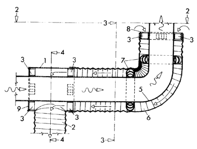
Figure 1 is a longitudinal section indicated by line 1-1
in Figure 2, illustrating the device in an arrangement
designed for operation within circulation of heated air.
Figure 2 is a view, partly in section indicated by line
2-2 in Figure 1.
Figures 3 and 4 are cross sections indicated by the
correspondingly numbered lines in Figure 1.
Figure 5 is a longitudinal section indicated by line 5-5
in Figure 6, illustrating the device in a modified
arrangement designed for operation within circulation of
heated air.
Figure 6 is a view indicated by line 6-6 in Figure 5.
Figure 7 is a cross section indicated by line 7-7 in
Figure 5.
Figure 8 is a longitudinal section indicated by line 8-8
in Figure 9, illustrating the device in an arrangement
designed for operation outside circulation of heated air.
Figure 9 is a view, partly in section indicated by line
9-9 in Figure 8.
Figures 10 and 11 are cross sections indicated by the
correspondingly numbered lines in Figure 8.
Figure 12 illustrates an application of my invention in
combination with a fan controlled by a thermostatic
switch. The same also illustrates schematically my
invention in an application outside circulation of heated
air.
-3-


CA 02499865 2005-03-24
Figure 13 illustrates an application of my invention in
combination with a fan, having its operation synchronized
with operation of a flue gas generating power burner. The
same also illustrates schematically my invention in an
application within circulation of heated air.
Figure 14 illustrates an application of my invention in
combination with a forced air combustion furnace
operating outside circulation of heated air.
Figure 15 illustrates an application of my invention
combination with a forced air combustion furnace
operating within circulation of heated air.
Referring to the drawings illustrating the device,
1 indicates a split sheet-metal cylinder with a heat
reflecting finish, equipped with an air duct 2, spacers
3, and bolted joint 4, that facilitates installation and
fastening the said cylinder to a flue 5, which is made
of galvanized steel. The sheet-metal cylinder is extended
by a heat reflecting flexible duct 6 of the same
diameter, held in concentrical position to the flue by
means of extension coil springs 7, wrapped around the
flue where necessary. The other end of the flexible duct
is either held in a desired position by a sheet-metal
ring 8, provided with spacers 3, or is connected to
another sheet-metal cylinder 1, equipped with an air
duct, spacers and a bolted joint, as illustrated in
Figures 8-11. In any arrangement, the open end of the
_4-


CA 02499865 2005-03-24
cylinder, which is not connected to the flexible duct 6,
is blocked by a sheet-metal annulus 9.
Referring to the drawings illustrating applications of
the device in combination with a fan, 10 indicates a
motor-driven fan generating air flow through a device 11,
which represents an apparatus designed to operate outside
circulation of heated air, as described in Figures 8-11,
yr through a device 12, which represents an apparatus
designed to operate within circulation of heated air, as
described in Figures 1-4 or 5-7. This air flow reclaims
flue gas heat and conveys it into a desired room.
Operation of the said motor-driven fan may be controlled
by a normally open thermostatic switch 13, which closes
the circuit only for the periods when the temperature of
flue gas is in excess of a certain preset limit, or it
may be synchronized with a flue gas generating power
burner 14, which, as a component of a heater or furnace,
is controlled by its own thermostat 15.
Referring to the drawings illustrating application of the
device in combination with a forced air combustion
central home-heating furnace, 16 indicates a sheet-metal
baffle restricting the regular intake of return air into
a furnace proportionally with added intake through the
device 11 or 12 communicating directly with a return air
duct or plenum 17 of the said furnace. Consequently, when
the furnace blower 18 is in operation, the generated
-5-


CA 02499865 2005-03-24
negative pressure in the return air plenum conveys a
certain portion of return air into the furnace via the
device il or 12. This portion of return air reclaims flue
gas heat and transfers it to the rest of return air,
increasing thus ultimately the temperature of supply air.
_6_

Representative Drawing
A single figure which represents the drawing illustrating the invention.
Administrative Status

For a clearer understanding of the status of the application/patent presented on this page, the site Disclaimer , as well as the definitions for Patent , Administrative Status , Maintenance Fee  and Payment History  should be consulted.

Administrative Status

Title Date
Forecasted Issue Date 2012-06-12
(22) Filed 2005-03-24
(41) Open to Public Inspection 2006-09-24
Examination Requested 2008-12-31
(45) Issued 2012-06-12
Deemed Expired 2020-08-31

Abandonment History

There is no abandonment history.

Payment History

Fee Type Anniversary Year Due Date Amount Paid Paid Date
Application Fee $200.00 2005-03-24
Maintenance Fee - Application - New Act 2 2007-03-26 $50.00 2007-01-30
Maintenance Fee - Application - New Act 3 2008-03-25 $50.00 2008-01-02
Request for Examination $400.00 2008-12-31
Maintenance Fee - Application - New Act 4 2009-03-24 $50.00 2009-03-02
Maintenance Fee - Application - New Act 5 2010-03-24 $100.00 2010-03-01
Maintenance Fee - Application - New Act 6 2011-03-24 $100.00 2011-03-09
Maintenance Fee - Application - New Act 7 2012-03-26 $100.00 2012-03-12
Final Fee $150.00 2012-03-28
Maintenance Fee - Patent - New Act 8 2013-03-25 $100.00 2013-03-13
Maintenance Fee - Patent - New Act 9 2014-03-24 $100.00 2014-02-07
Maintenance Fee - Patent - New Act 10 2015-03-24 $125.00 2015-02-09
Maintenance Fee - Patent - New Act 11 2016-03-24 $125.00 2016-01-18
Maintenance Fee - Patent - New Act 12 2017-03-24 $125.00 2017-01-13
Maintenance Fee - Patent - New Act 13 2018-03-26 $125.00 2018-03-12
Owners on Record

Note: Records showing the ownership history in alphabetical order.

Current Owners on Record
RYBAK, MILAN
Past Owners on Record
None
Past Owners that do not appear in the "Owners on Record" listing will appear in other documentation within the application.
Documents

To view selected files, please enter reCAPTCHA code :


To view images, click a link in the Document Description column. To download the documents, select one or more checkboxes in the first column and then click the "Download Selected in PDF format (Zip Archive)" or the "Download Selected as Single PDF" button.

List of published and non-published patent-specific documents on the CPD .

If you have any difficulty accessing content, you can call the Client Service Centre at 1-866-997-1936 or send them an e-mail at CIPO Client Service Centre.


Document
Description 
Date
(yyyy-mm-dd) 
Number of pages   Size of Image (KB) 
Abstract 2005-03-24 1 20
Description 2005-03-24 6 200
Claims 2005-03-24 1 32
Drawings 2005-03-24 5 144
Representative Drawing 2006-01-23 1 12
Cover Page 2006-09-12 2 43
Claims 2012-01-04 1 34
Cover Page 2012-05-15 2 43
Prosecution-Amendment 2010-06-21 1 35
Prosecution-Amendment 2011-04-05 2 102
Correspondence 2005-04-13 1 13
Assignment 2005-03-24 4 109
Prosecution-Amendment 2011-07-20 2 48
Fees 2007-01-29 1 19
Maintenance Fee Payment 2018-03-12 1 19
Fees 2008-01-02 1 45
Fees 2010-03-01 1 47
Prosecution-Amendment 2008-12-31 1 19
Fees 2009-03-02 1 45
Prosecution-Amendment 2010-01-07 2 52
Prosecution-Amendment 2010-10-15 2 69
Fees 2011-03-09 1 104
Maintenance Fee Payment 2019-04-11 1 24
Prosecution-Amendment 2012-01-04 2 59
Fees 2012-03-12 1 21
Correspondence 2012-03-28 2 90
Fees 2013-03-13 1 21
Fees 2014-02-07 1 20
Fees 2015-02-09 1 19
Maintenance Fee Payment 2016-01-18 1 17
Maintenance Fee Payment 2017-01-13 3 46