Some of the information on this Web page has been provided by external sources. The Government of Canada is not responsible for the accuracy, reliability or currency of the information supplied by external sources. Users wishing to rely upon this information should consult directly with the source of the information. Content provided by external sources is not subject to official languages, privacy and accessibility requirements.
Any discrepancies in the text and image of the Claims and Abstract are due to differing posting times. Text of the Claims and Abstract are posted:
| (12) Patent Application: | (11) CA 2499881 |
|---|---|
| (54) English Title: | CREDIT CARD CASE WITH QUICK-RELEASE LATCH |
| (54) French Title: | PORTE-CARTES DE CREDIT POURVU D'UN SYSTEME D'ACCROCHAGE A OUVERTURE RAPIDE |
| Status: | Deemed Abandoned and Beyond the Period of Reinstatement - Pending Response to Notice of Disregarded Communication |
| (51) International Patent Classification (IPC): |
|
|---|---|
| (72) Inventors : |
|
| (73) Owners : |
|
| (71) Applicants : |
|
| (74) Agent: | KIRBY EADES GALE BAKER |
| (74) Associate agent: | |
| (45) Issued: | |
| (86) PCT Filing Date: | 2003-10-09 |
| (87) Open to Public Inspection: | 2004-04-22 |
| Availability of licence: | N/A |
| Dedicated to the Public: | N/A |
| (25) Language of filing: | English |
| Patent Cooperation Treaty (PCT): | Yes |
|---|---|
| (86) PCT Filing Number: | PCT/US2003/032069 |
| (87) International Publication Number: | WO 2004032662 |
| (85) National Entry: | 2005-03-22 |
| (30) Application Priority Data: | ||||||
|---|---|---|---|---|---|---|
|
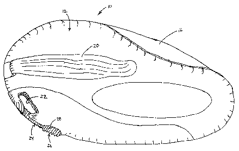
A credit card case (10)or fob with an integrated quick-release latch (24) is
provided that may be unclipped readily from a key loop, key chain or other
device. The quick-release credit card case (10) includes upper (12) and lower
(14) cover portions and a pivot member for connecting the upper and lower
cover portions. The pivot member is adapted to have at least one card mounted
thereon so as to permit pivotal rotation of the card (16) relative to the
upper and lower (14) cover portions. The upper (12) and lower (14) cover
portions each have a slot (22) in an outer surface thereof at mateably aligned
locations to permit insertion of a key chain loop therein. A latch (24)
mounted on at least one of the cover portions (12, 14) is selectively movable
to alternate positions exposing the radially outwardly facing opening of the
slot (22) in said cover portions (12, 14) and closing said radially outwardly
facing opening of the slot (22) in said cover portions (12, 14).
L'invention concerne un porte-cartes de crédit pourvu d'un système d'accrochage à ouverture rapide intégré, ce porte-cartes pouvant être décroché facilement d'un porte-clés, d'une chaîne porte-clés ou d'un autre dispositif. Ce porte-cartes de crédit à décrochage rapide comprend des parties de recouvrement supérieure et inférieure, ainsi qu'un élément de pivotement reliant ces deux parties. Cet élément de pivotement est conçu de telle sorte qu'au moins une carte puisse être montée sur ledit élément de façon à pouvoir pivoter par rapport aux parties de recouvrement supérieure et inférieure. Lesdites parties de recouvrement supérieure et inférieure comportent chacune dans leur surface extérieure une fente ménagée à des emplacements correspondants de sorte qu'un anneau de chaîne porte-clés puisse y être inséré. Un système d'accrochage monté sur au moins une des parties de recouvrement peut être déplacé sélectivement entre une position faisant apparaître dans ces parties de recouvrement l'ouverture de la fente tournée vers l'extérieur radialement et une position obturant ladite ouverture dans lesdites parties.
Note: Claims are shown in the official language in which they were submitted.
Note: Descriptions are shown in the official language in which they were submitted.
2024-08-01:As part of the Next Generation Patents (NGP) transition, the Canadian Patents Database (CPD) now contains a more detailed Event History, which replicates the Event Log of our new back-office solution.
Please note that "Inactive:" events refers to events no longer in use in our new back-office solution.
For a clearer understanding of the status of the application/patent presented on this page, the site Disclaimer , as well as the definitions for Patent , Event History , Maintenance Fee and Payment History should be consulted.
| Description | Date |
|---|---|
| Time Limit for Reversal Expired | 2009-10-09 |
| Application Not Reinstated by Deadline | 2009-10-09 |
| Inactive: Abandon-RFE+Late fee unpaid-Correspondence sent | 2008-10-09 |
| Deemed Abandoned - Failure to Respond to Maintenance Fee Notice | 2008-10-09 |
| Inactive: IPRP received | 2007-03-16 |
| Letter Sent | 2006-03-16 |
| Inactive: IPC from MCD | 2006-03-12 |
| Inactive: Multiple transfers | 2006-02-06 |
| Inactive: Cover page published | 2005-06-13 |
| Letter Sent | 2005-06-07 |
| Inactive: Notice - National entry - No RFE | 2005-06-07 |
| Application Received - PCT | 2005-04-13 |
| National Entry Requirements Determined Compliant | 2005-03-22 |
| National Entry Requirements Determined Compliant | 2005-03-22 |
| Application Published (Open to Public Inspection) | 2004-04-22 |
| Abandonment Date | Reason | Reinstatement Date |
|---|---|---|
| 2008-10-09 |
The last payment was received on 2007-09-13
Note : If the full payment has not been received on or before the date indicated, a further fee may be required which may be one of the following
Please refer to the CIPO Patent Fees web page to see all current fee amounts.
| Fee Type | Anniversary Year | Due Date | Paid Date |
|---|---|---|---|
| Registration of a document | 2005-03-22 | ||
| Basic national fee - standard | 2005-03-22 | ||
| MF (application, 2nd anniv.) - standard | 02 | 2005-10-11 | 2005-09-21 |
| Registration of a document | 2006-02-06 | ||
| MF (application, 3rd anniv.) - standard | 03 | 2006-10-10 | 2006-09-14 |
| MF (application, 4th anniv.) - standard | 04 | 2007-10-09 | 2007-09-13 |
Note: Records showing the ownership history in alphabetical order.
| Current Owners on Record |
|---|
| DISCOVER FINANCIAL SERVICES LLC |
| Past Owners on Record |
|---|
| DAVID W. NELMS |
| RODNEY A. DAWSON |

