Sélection de la langue

Search

Sommaire du brevet 2499881 

Énoncé de désistement de responsabilité concernant l'information provenant de tiers

Une partie des informations de ce site Web a été fournie par des sources externes. Le gouvernement du Canada n'assume aucune responsabilité concernant la précision, l'actualité ou la fiabilité des informations fournies par les sources externes. Les utilisateurs qui désirent employer cette information devraient consulter directement la source des informations. Le contenu fourni par les sources externes n'est pas assujetti aux exigences sur les langues officielles, la protection des renseignements personnels et l'accessibilité.

Disponibilité de l'Abrégé et des Revendications

L'apparition de différences dans le texte et l'image des Revendications et de l'Abrégé dépend du moment auquel le document est publié. Les textes des Revendications et de l'Abrégé sont affichés :

  • lorsque la demande peut être examinée par le public;
  • lorsque le brevet est émis (délivrance).
(12) Demande de brevet: (11) CA 2499881
(54) Titre français: PORTE-CARTES DE CREDIT POURVU D'UN SYSTEME D'ACCROCHAGE A OUVERTURE RAPIDE
(54) Titre anglais: CREDIT CARD CASE WITH QUICK-RELEASE LATCH
Statut: Morte
Données bibliographiques
(51) Classification internationale des brevets (CIB):
  • A45C 11/18 (2006.01)
  • A45F 5/02 (2006.01)
  • A45C 11/32 (2006.01)
(72) Inventeurs :
  • NELMS, DAVID W. (Etats-Unis d'Amérique)
  • DAWSON, RODNEY A. (Etats-Unis d'Amérique)
(73) Titulaires :
  • DISCOVER FINANCIAL SERVICES LLC (Etats-Unis d'Amérique)
(71) Demandeurs :
  • DISCOVER FINANCIAL SERVICES, INC. (Etats-Unis d'Amérique)
(74) Agent: KIRBY EADES GALE BAKER
(74) Co-agent:
(45) Délivré:
(86) Date de dépôt PCT: 2003-10-09
(87) Mise à la disponibilité du public: 2004-04-22
Licence disponible: S.O.
(25) Langue des documents déposés: Anglais

Traité de coopération en matière de brevets (PCT): Oui
(86) Numéro de la demande PCT: PCT/US2003/032069
(87) Numéro de publication internationale PCT: WO2004/032662
(85) Entrée nationale: 2005-03-22

(30) Données de priorité de la demande:
Numéro de la demande Pays / territoire Date
60/417,545 Etats-Unis d'Amérique 2002-10-10

Abrégés

Abrégé français

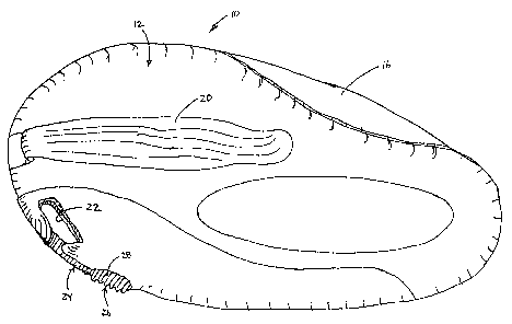
L'invention concerne un porte-cartes de crédit pourvu d'un système d'accrochage à ouverture rapide intégré, ce porte-cartes pouvant être décroché facilement d'un porte-clés, d'une chaîne porte-clés ou d'un autre dispositif. Ce porte-cartes de crédit à décrochage rapide comprend des parties de recouvrement supérieure et inférieure, ainsi qu'un élément de pivotement reliant ces deux parties. Cet élément de pivotement est conçu de telle sorte qu'au moins une carte puisse être montée sur ledit élément de façon à pouvoir pivoter par rapport aux parties de recouvrement supérieure et inférieure. Lesdites parties de recouvrement supérieure et inférieure comportent chacune dans leur surface extérieure une fente ménagée à des emplacements correspondants de sorte qu'un anneau de chaîne porte-clés puisse y être inséré. Un système d'accrochage monté sur au moins une des parties de recouvrement peut être déplacé sélectivement entre une position faisant apparaître dans ces parties de recouvrement l'ouverture de la fente tournée vers l'extérieur radialement et une position obturant ladite ouverture dans lesdites parties.


Abrégé anglais


A credit card case (10)or fob with an integrated quick-release latch (24) is
provided that may be unclipped readily from a key loop, key chain or other
device. The quick-release credit card case (10) includes upper (12) and lower
(14) cover portions and a pivot member for connecting the upper and lower
cover portions. The pivot member is adapted to have at least one card mounted
thereon so as to permit pivotal rotation of the card (16) relative to the
upper and lower (14) cover portions. The upper (12) and lower (14) cover
portions each have a slot (22) in an outer surface thereof at mateably aligned
locations to permit insertion of a key chain loop therein. A latch (24)
mounted on at least one of the cover portions (12, 14) is selectively movable
to alternate positions exposing the radially outwardly facing opening of the
slot (22) in said cover portions (12, 14) and closing said radially outwardly
facing opening of the slot (22) in said cover portions (12, 14).

Revendications

Note : Les revendications sont présentées dans la langue officielle dans laquelle elles ont été soumises.


WE CLAIM:

1. A case having a slot in the periphery of the case, comprising:
a stop surface positioned on a first side of the slot;
a latch slidably attached on a second side of the slot, the second side being
opposed to the first side, the latch comprising:
a main section having an extension; and
a tail section;
a flange for receiving the tail section, wherein the tail section provides a
spring function that biases the extension of the latch to contact with stop
surface.

2. A case as in claim 1 wherein the latch is integrally formed.

3. A case as in claim 1 wherein the case includes a rail and the latch
engages the rail.

4. A case as in claim 1 wherein the tail section a flat member that provides
the spring function by flexing when compressed against the flange.

5. A case as in claim 1 wherein the latch is plastic.

6. A case as in claim 1 wherein the tail section comprises two lengthwise
extending portions that are joined at the outer ends of the extending portions
by a
flat portion.

7. A case as in claim 6 wherein the flat portion includes a pin section for
engagement with the flange.

8. A case as in claim 1 wherein the case encases a credit card device.

9. A case as in claim 1 wherein the latch further includes a thumb pad
having a plurality of ridges.


8


10. A case having a slot in the periphery of the case, comprising:
a stop surface positioned on a first side of the slot;
a plastic latch slidably attached on a second side of the slot, the second
side
being opposed to the first side, the latch comprising:
a main section having an extension;
a thumb pad having a plurality of ridges; and
a tail section including two lengthwise extending portions that are
joined at the outer ends of the extending portions by a flat portion having a
pin
portion;
a flange for receiving the pin portion of the tail section, wherein the tail
section provides a spring function that biases the extension of the latch to
contact
with stop surface.

11. A method for forming a latch in a case having a slot in the periphery of
the case, comprising:
providing a stop surface positioned on a first side of the slot;
slidably attaching a latch on a second side of the slot, the second side being
opposed to the first side, the latch comprising:
a main section having an extension; and
a tail section;
providing a flange for receiving the tail section, wherein the tail section
provides a spring function that biases the extension of the latch to contact
with stop
surface.

12. A method as in claim 11 wherein the latch is integrally formed.

13. A method as in claim 11 wherein the case includes a rail and the latch
engages the rail.

14. A method as in claim 11 wherein the tail section a flat member that
provides the spring function by flexing when compressed against the flange.


9


15. A method as in claim 11 wherein the latch is plastic.

16. A method as in claim 11 wherein the tail section comprises two
lengthwise extending portions that are joined at the outer ends of the
extending
portions by a flat portion.

17. A method as in claim 16 wherein the flat portion includes a pin section
for engagement with the flange

18. A method as in claim 11 wherein the case encases a credit card device.

19. A method as in claim 11 wherein the latch further includes a thumb pad
having a plurality of ridges.


Description

Note : Les descriptions sont présentées dans la langue officielle dans laquelle elles ont été soumises.


CA 02499881 2005-03-22
WO 2004/032662 PCT/US2003/032069
CREDIT CARD CASE WITH QUICK-RELEASE LATCH
RELATED APPLICATIONS
This application is related to and claims the priority of U.S. Provisional
Application No. 60/417,545 filed October 10, 2002, the contents of which are
herein incorporated by reference.
BACKGROUND OF THE INVENTION
The present invention relates to a case, fob or article for holding one or
more credit cards, special value cards or other payment instrument, and
particularly
to a credit card case or fob that contains an integrated quick-release latch
that may
be unclipped readily from a key chain.
Suppliers of conventional credit cards and special value cards desire to
have their particular card carried by the user in a.~i accessible position
outside of a
wallet or a purse, for example on a key loop, key chain, or in a packet on a
readily
accessible device in order to increase the likelihood of usage of the card.
The
advantage of having the card accessible outside of a wallet or purse is that
the user
has the card available at his or her fingertips instead of having to open a
purse or
wallet and malce a choice to use a particular card or payment instrument from
among several possible choices.
In order to protect credit cards from theft of the card itself or the card
number when the card is carried on a key chain, cases or fobs have been
developed
for concealing the card. The person using the card normally opens the case,
container or fob without unclipping it from the key chain in order to pivot
the card
to an accessible position so that the card may be swiped through a magnetic
card
reader or, a radio frequency reader or other identification system. There are
occasions, however, when, in order to use the card, the case or container must
be


CA 02499881 2005-03-22
WO 2004/032662 PCT/US2003/032069
removed from the key chain. For example, it may be necessary to unclip the
case
from the chain in order to access the case for use at a fast food drive-in
when a key
on the chain is in the ignition of a car. Prior lcey chain cases typically
require
stopping the car engine, removing the key from the ignition, and using two
hands
to remove the case or container from the key chain. There is a need therefore
to
provide a credit card case with an integrated quick-release latch that can be
more
easily removed from a key chain in order to gain access to the case or to the
credit
card.
2


CA 02499881 2005-03-22
WO 2004/032662 PCT/US2003/032069
SUMMARY OF THE INVENTION
The present invention provides a credit card case that with an integrated
quick-release latch may be unclipped readily from a key loop or key chain.
In one embodiment the quick-release credit card case includes upper and
S lower cover portions and a pivot member for connecting the upper and lower
cover
portions. The pivot member is adapted to have at least one card mounted
thereon
so as to permit pivotal rotation of the card relative to the upper and lower
cover
portions. The upper and lower cover portions each have a slot in an outer
surface
thereof that can be aligned and mated to permit insertion of a key chain loop
therein. A latch mounted on at least one of the upper and lower cover portions
is
selectively movable to alternate positions. In a first position, the latch
exposes a
radially outwardly facing opening of the slot in said upper and lower cover
portions. In a second position, the latch closes or covers the radially
outwardly
facing opening of the slot. Preferably the latch includes a flexible spring-
like
portion for biasing the latch into a normally closed position covering the
radially
outwardly facing opening of the slot. Most preferably the latch is slidably
mounted
on a track formed on an outer peripheral surface of one of the cover portions
and
the flexible spring-like portion of the latch comprises an extension engaging
a
flange on said one of the cover portions. The quick-release credit card case,
container or fob of the invention may be removed by using one hand from a key
chain or lcey loop or from whatever item to which the case is attached, such
as a
belt loop, laptop computer case, clothing, purse, brief case, or personal
digital
assistant case. A person is able to grasp the case of the invention with one
hand and
move the quick-release latch to an open position by movement of the thumb of
that
hand without using their other hand at all.


CA 02499881 2005-03-22
WO 2004/032662 PCT/US2003/032069
BRIEF DESCRIPTION OF THE DRAWINGS
In the drawings, which are not to scale:
Figures 1 are a perspective view of one side of the quick-release credit card
case of the present invention.
Figures 2 are a perspective view of the reverse side of the quiclc release
credit card case of Figure 1.
Figures 3 are a perspective view similar to Figure 2 showing the latch in an
open position exposing a lcey chain slot in the case.
Figures 4 are a partial perspective view of the interior surface of the upper
cover showing the latch mounted on a track of the upper cover with the latch
in
closed position covering the slot opening.
Figures 5 are a partial perspective view similar to Figure 4 showing the
latch in the open position.
Figures 6 are a perspective view of the latch showing a flexible spring-lilce
tail section of the latch.
Figures 7 are a partial view of the interior of the upper cover showing the
latch in open position with the end of the flexible spring-like tail section
of the
latch abutted against a flange in the upper cover.
Figure 8 is a top perspective view of an alternative embodiment.
4


CA 02499881 2005-03-22
WO 2004/032662 PCT/US2003/032069
DETAILED DESCRIPTION OF THE PREFERRED EMBODIMENTS
The present invention provides a credit card case with an integrated quiclc-
release latch which may be unclipped readily from a key loop, key chain, or
other
item.
Figures 1 and 2 show quick-release credit card case 10 having an upper
cover portion 12 (Fig. 1) and a lower cover portion 14 (Fig. 2). Credit card
16 is
pivotally mounted in case 10 on a pivot member. Card 16 partially extends
beyond
the outer periphery of the case so as to permit the card to be grasped by a
person's
thumb and forefinger and pivoted to an exposed position downwardly of the case
in Figure l and upwardly in Figure 2 (not illustrated in either Figure). The
pivot
member may be a rivet or post as known in the art. Preferably the card is
detachable from the pivot member in order to be fully removed from the case.
This
may be accomplished by providing a knurled opening in the card, said opening
having an open end for the pivot connection to the pivot member. A description
of
a card having such an opening and pivotal connection is set forth in PCT/LTS
Application Serial No. PCT/US02/22,933, entitled "Credit Card With Case" filed
July 17, 2002, the entire specification of which is incorporated herein by
reference.
A clip 20 is preferably provided for holding currency, a driver's license or
attaching the case to other items against upper cover portion 12. Slot or
aperture 22
is provided in upper and lower cover portions 12 and 14 to permit passage of a
key
chain loop. Preferably slot 22 is of arc shape having a substantially circular
inner
surface. Latch 24 is provided for alternately exposing and closing a radially
outwardly facing opening (Fig. 3) of slot 22. Latch 24 is shown in closed
position
covering the radially outwardly facing opening of slot 22 in Figures 1 and 2
and in
the retracted open position exposing said opening in Figure 3. Latch 24
preferably
has a thumb pad 26 with a plurality of ridges 28 on an outer surface of the
pad to
provide friction when engaged by the thumb or finger of a person's hand in
order
to permit ease of movement of the latch.
5


CA 02499881 2005-03-22
WO 2004/032662 PCT/US2003/032069
Referring to Figures 4 and 5, upper cover portion 12 has a track or rail 30
comprising a flat head section 32 and a web section 34 extending lengthwise
from
an edge of slot 22 along a portion of the outer periphery of cover portionl2.
Other
traclc or rail configurations may be used such as spaced parallel tracks on
either the
latch or the cover portion that receive a flange of the cover portion or latch
to ride
between the tracks. Cover portion 12 has a curved stop surface 36 on an
opposite
edge of slot 22 from track or rail 30. Cover portion 12 also has a stop
surface 38 at
the end of track 30. Stop surfaces 36 and 38 serve to limit the extent of
slidable
movement of latch 24 on track 30 to its respective open and closed positions.
Latch
24 has a longitudinal flat head portion 40 and a web portion 42 for riding
slidably
on flat head section 32 and web section 34 of track 30. Latch 24 has a curved
surface 44 at one end for engagement with curved stop surface 36 on the edge
of
slot 22.
Referring to Figures 6 and 7, latch 24 has a flexible spring-like tail section
46 comprising two lengthwise extending portions 48 and 50 that are joined at
their
outer ends by flat portion 52. Pin section 54 extends transversely of flat
portion 52
for engagement in angular flange 56 (Fig. 7) of cover portion 12. Radial
flanges 58
and 60 guide tail section 46 when latch 24 is slidably moved back and forth to
alternate open and closed positions. Latch 24 is preferably comprised of
plastic
material having both strength and flexibility with memory properties providing
spring-like characteristics in flexible tail section 46. Preferably tail
section 46 is
molded so as to be an integral part of latch 24 although that is not required.
The tail
may be a separate section attached to latch 24 or engageable with latch 24.
Referring to Figure 8, an alternative embodiment of the case 10 with credit
card 16 and aperture 22. A key pad 70 is included in the top of the case with
one or
more keys 72 located on the pad. Presently, many automobile users have a fob
or
other device that hangs from their keys and includes a key pad with keys for
remote access to the automobile. These remote access keys include the ability
to,
for example, unlock car doors, open or roll-down windows, unlatch a trunk, or
6


CA 02499881 2005-03-22
WO 2004/032662 PCT/US2003/032069
activate a garage door opener or other key-less entry device. The embodiment
of
Figure ~ contemplates inclusion of the standard keypad with automobile remote
access keys onto the case for the card, along with the associated electronics
needed
to operate the remote access lceys. With this embodiment, the user avoids
needing a
second key fob for maintaining automobile remote access devices, which are
combined with the credit card case.
While a preferred embodiment of the invention has been identified, other
configurations and modifications can be provided within the scope of the
present
invention. For example, it is conceivable that only one cover portion may be
required depending on the type of card to be carried in the case, it being
necessary
to protect only the surface of the card containing the card number and other
identification information or means. It is also conceivable that a single
integral
cover could be provided for covering both sides of the card rather than
separate
upper and lower cover portions. Other configurations of quick release means
could
also be provided. For example, a rotatable latch could be provided that would
rotate in a plane parallel to one of the cover portions in order to
alternately expose
and close the slot opening.
7

Dessin représentatif
Une figure unique qui représente un dessin illustrant l'invention.
États administratifs

Pour une meilleure compréhension de l'état de la demande ou brevet qui figure sur cette page, la rubrique Mise en garde , et les descriptions de Brevet , États administratifs , Taxes périodiques et Historique des paiements devraient être consultées.

États administratifs

Titre Date
Date de délivrance prévu Non disponible
(86) Date de dépôt PCT 2003-10-09
(87) Date de publication PCT 2004-04-22
(85) Entrée nationale 2005-03-22
Demande morte 2009-10-09

Historique d'abandonnement

Date d'abandonnement Raison Reinstatement Date
2008-10-09 Taxe périodique sur la demande impayée
2008-10-09 Absence de requête d'examen

Historique des paiements

Type de taxes Anniversaire Échéance Montant payé Date payée
Enregistrement de documents 100,00 $ 2005-03-22
Le dépôt d'une demande de brevet 400,00 $ 2005-03-22
Taxe de maintien en état - Demande - nouvelle loi 2 2005-10-11 100,00 $ 2005-09-21
Enregistrement de documents 100,00 $ 2006-02-06
Taxe de maintien en état - Demande - nouvelle loi 3 2006-10-10 100,00 $ 2006-09-14
Taxe de maintien en état - Demande - nouvelle loi 4 2007-10-09 100,00 $ 2007-09-13
Titulaires au dossier

Les titulaires actuels et antérieures au dossier sont affichés en ordre alphabétique.

Titulaires actuels au dossier
DISCOVER FINANCIAL SERVICES LLC
Titulaires antérieures au dossier
DAWSON, RODNEY A.
DISCOVER FINANCIAL SERVICES, INC.
NELMS, DAVID W.
Les propriétaires antérieurs qui ne figurent pas dans la liste des « Propriétaires au dossier » apparaîtront dans d'autres documents au dossier.
Documents

Pour visionner les fichiers sélectionnés, entrer le code reCAPTCHA :


Pour visualiser une image, cliquer sur un lien dans la colonne description du document. Pour télécharger l'image (les images), cliquer l'une ou plusieurs cases à cocher dans la première colonne et ensuite cliquer sur le bouton "Télécharger sélection en format PDF (archive Zip)" ou le bouton "Télécharger sélection (en un fichier PDF fusionné)".

Liste des documents de brevet publiés et non publiés sur la BDBC .

Si vous avez des difficultés à accéder au contenu, veuillez communiquer avec le Centre de services à la clientèle au 1-866-997-1936, ou envoyer un courriel au Centre de service à la clientèle de l'OPIC.


Description du
Document 
Date
(yyyy-mm-dd) 
Nombre de pages   Taille de l'image (Ko) 
Page couverture 2005-06-13 1 49
Dessins 2005-03-22 8 136
Revendications 2005-03-22 3 84
Abrégé 2005-03-22 2 74
Description 2005-03-22 7 280
Dessins représentatifs 2005-06-10 1 12
PCT 2005-03-22 3 87
Cession 2005-03-22 9 298
Cession 2006-02-06 9 239
PCT 2007-03-16 3 181