Note: Descriptions are shown in the official language in which they were submitted.
CA 02499912 2005-03-09
A LAMINATE SHEET FOR SECURITY BOOKLETS
AND METHOD FOR MAKING SAME
Field of the Invention
[00001] This invention relates generally to the field of security documents in
the
form of a booklet having multiple pages bound together by suitable means, and
in
particular to a laminate sheet for inclusion as a page of such a booklet.
Background of the Invention
[00002] Security booklets, such as travel documents (e.g. passports),
typically
comprise multiple pages which are bound together along an edge of the booklet
(for
example, by sewing sheets together down the middle and then folding them at
the
sewing line) one such page typically being a machine-readable information
sheet in
accordance with ICAO (International Civil Aviation Organization)
specifications and
comprising various printed security features, a photograph and other personal
information identifying the document holder. More recently, this information
sheet, or
another information sheet of the security booklet, may comprise an embedded
contactless integrated circuit chip and antenna which form part of a security
system
designed to enhance the level of security associated with the travel document.
Similarly, another information sheet of the security booklet could be used as
a carrier
forother high capacity electronic storage media such as contact-based
integrated circuit
chips, magnetic strips and optical memories.
[00003] Depending on the function and composition of the information sheet it
may
be necessary, or desirable, that it be made of a hard and durable synthetic
material
differing substantially in character from the remaining pages of the booklet
which,
typically, are comprised of a soft and pliable paper that can be sewn together
and
withstand repetitive bending and flexing at the bound edge. This is because of
certain
improved security measures which may now be applied to the personalization of
such
security booklets, such as the use of laser engraving and/or the use of a
contactless
1
CA 02499912 2005-03-09
integrated circuit chip and antenna embedded within the information sheet
itself. These
improved security measures require that such an information sheet be hard,
durable and
thicker than the accompanying paper sheets with which it must be bound and, in
turn,
the harder, thicker character of such information sheet presents a problem as
to how to
durably and securely bind them within the booklet.
[00004] This problem arises because a hard, durable sheet material cannot be
satisfactorily bound, at one of its edges, with pliable sheets, so as to form
part of a travel
document such as a passport. Such materials are too hard for the sewing
process and
cannot be folded as needed for the sewing/binding process. Moreover, a hard
material
fixed into the binding would not be able to withstand the normal, day-to-day,
flexing and
bending that travel documents may be subjected to over the term of their use.
[00005] To overcome this problem, it is necessary to find a method of securely
binding a hard, durable sheet, capable of functioning as an information sheet,
to a
flexible band that can be effectively bound into a booklet and provide the
required
flexibility and durability, for usage, at the binding edge. If like materials
are selected for
the durable sheet and flexible binding edge portion, these can be laminated
together to
form the desired construction having such a flexible edge piece for binding
into a
booklet, an example of such a construction being European Patent Application
No. EP
1,245,407 of Setec Oy published on 27 March, 2002. However, where dissimilar
materials are desired for the durable sheet and the binding edge, lamination
may not
provide an acceptable option since dissimilar materials may not effectively
laminate to
each other.
[00006] U.S. Patent No. 6,213,702 to Wesselink, issued 10 April, 2001,
discloses
a possible solution to such problem posed by dissimilar materials, whereby a
flexible
band is affixed to a finished synthetic, hard sheet, referred to as a plate,
by means of
a separate joining strip positioned over the band. The joining strip is
configured with
projections to mechanically fit into mating perforations formed along the edge
of the
2
CA 02499912 2005-03-09
flexible band which is positioned over the hard sheet, such that the only
direct
connection made is between the joining strip and the plate, the connecting
surfaces
being the bottom surfaces of the projections and the top surfaces of the plate
exposed
by the perforations in the band. Those connecting surfaces of the separate
joining strip
and the plate are affixed by means of either a mechanical clamping fit between
the
projections and perforations or by fusing them together (i.e. by melting them
together
by ultrasonic welding if the material used for the joining strip is the same
as that of the
plate). However that possible solution has the disadvantage of requiring use
of a
separate joining strip.
[00007] European Patent Application No. EP 1,380,442 of Setec Oy, published on
14 January, 2004, and U.S. Patent No. 6,135,503 to Lob et al., issued on 24
October,
2000, each disclose an identification document comprising a durable data sheet
with a
more flexible edge for binding with additional booklet sheets, whereby the
durable sheet
is formed by laminating plastic layers together in the data area of those
sheets but
preventing such lamination from occurring at the edges of those sheets by
providing
intermediary separation layers between them in only that edge area. Thus,
these
methods require the step of specifically positioning such intermediary
separation layers
in the edge area.
[00008] Accordingly, there remains a need for means to securely couple
together
dissimilar first and second materials, one being a hard, core material and the
other
being a flexible material suitable to be bound with paper sheets by sewing
them
together, without any need for a separate joining component or separate
separation
layers.
Summary of the Invention
[00009] In accordance with the invention there is provided a hard laminate
sheet
for security booklets, comprising at least two hard core layers and a flexible
component
there between and extending beyond an outer edge of the core layers to form a
flexible
3
CA 02499912 2005-03-09
band. The flexible component may be provided as an intermediate layer
comprising a
hard component juxtaposed with flexible component and laminated to the
adjacent core
layers. The flexible component comprises a plurality of apertures within which
material
of the adjacent core layers is laminated together and affixes the flexible
component to
the laminate sheet. Preferably, a plurality of additional hard core layers are
directly or
indirectly laminated to the two core layers which sandwich the flexible
component (or
intermediate layer). The core layers, and hard component of the intermediate
layer,
may, optionally, comprise polycarbonate. The flexible component may,
optionally,
comprise nylon.
[00010] For selected applications the laminate sheet may be preferably
configured
for laser engraving and/or may comprise a hard core inlay layer for embedding
a
contactiess integrated circuit chip and antenna.
[00011] In accordance with a further aspect of the invention there is provided
a
method for making a hard laminate sheet for security booklets, comprising the
steps of
providing at least two hard core layers (e.g. of polycarbonate) and a flexible
component
(e.g. of nylon) positioned there between and extending beyond an outer edge of
the
core layers to form a flexible band, whereby the flexible component comprises
a plurality
of apertures. The flexible component may be provided as an intermediate layer
comprising a hard component (e.g. of polycarbonate) juxtaposed with the
flexible
component. These layers are then laminated to produce core-to-core bonds
between
the adjacent hard core layers (including the hard component of the
intermediate layer)
and a core-to-core bond within the apertures of the flexible component from
material of
the core layers adjacent the flexible component such that that core-to-core
bond, within
the apertures, affixes the flexible component to the laminate sheet.
Preferably, a
plurality of hard core layers are directly or indirectly laminated to the core
layers
sandwiching the flexible component.
Description of the Drawings
4
CA 02499912 2005-03-09
[00012] The present invention is described below with reference to the
following
drawings in which like reference numerals refer throughout to like elements.
[00013] Figure 1 is a cross-sectional view of a hard, durable, composite,
laminate
sheet having an integral flexible band extending therefrom, showing the core
laminate
and flexible band layers arranged in accordance with the invention;
[00014] Figure 2 is a plan view of an intermediate layer of the composite,
laminate
sheet of Figure 1, this intermediate layer being made up of separate,
juxtaposed
components each comprised of a different material, one being the hard, durable
core
material and positioned on the left-hand-side, and the other being the
flexible material
of the band and positioned adjacent the core material component on the right-
hand-side
thereof, the flexible material component including a plurality of spaced
apertures along
an edge adjacent the core material component;
[00015] Figure 3 is an exploded view representation of the composite, laminate
sheet of Figure 1, showing the relative positioning of each layer thereof
including the
intermediate layer comprising the flexible material of the band shown
separately by
Figure 2; and,
[00016] Figure 4 is a schematic, conceptual-type illustration which is
provided to
illustrate an integration of the flexible band component of the intermediate
layer into the
composite, laminate sheet whereby the adjacent core material layers positioned
above
and below the flexible band component have melted into and combined within the
area
of the apertures of the flexible band component.
Description of the Illustrated Embodiment
[00017] The inventors herein have developed a method for making a hard,
durable
synthetic page (interchangeably also referred to herein as a laminate sheet)
comprised
of a composite laminate of hard core material layers of which two such layers
encase
CA 02499912 2005-03-09
a flexible material layer such that a flexible band is formed and extends from
the
laminate sheet. As a whole, the laminate sheet advantageously constitutes a
secure,
tamper-resistant monolithic structure suitable for use in a security document
such as a
travel document. This method, and the security booklet produced therefrom, are
described below with reference to an embodiment illustrated by the drawings.
[00018] The use of a hard, durable synthetic sheet, for example a
polycarbonate
sheet, within security booklets is becoming increasingly desirable because
such
materials provide greater security than paper sheets; they can be laser
engraved with
personal details of the booklet holder and can provide a durable shell for an
embedded
contactiess integrated circuit chip (where desired). However, such use
presents
difficulties for the manufacturing of security booklets because a hard page
cannot itself
be directly bound within a booklet; instead, it becomes necessary to securely
coupled
such hard page to a flexible band whereby such flexible band is directly bound
(e.g. by
sewing) to the other pages of the booklet.
[00019] As will be recognized by persons skilled in the art, the task of
laminating
or gluing together two dissimilar materials, such as a hard, polycarbonate
material and
a flexible material such as nylon, is problematic if it is desired to achieve
a secure bond
between the dissimilar materials i.e. so that they cannot be peeled away from
each other
(for obvious reasons, any propensity for such peeling away between layers of
the sheet
materials is not acceptable for security document applications). Consequently,
in order
to couple a flexible band material, of a type that can be sewn into a security
booklet, to
a hard core laminate sheet it is desirable to avoid any direct coupling of
those dissimilar
materials. The aforementioned U.S. Patent No. 6,213,702 to Wesselink provides
a
means of indirect coupling of such dissimilar materials using a separate
joining strip.
By contrast, the inventors herein have developed means to achieve the
necessary
indirect coupling without need for any such additional component.
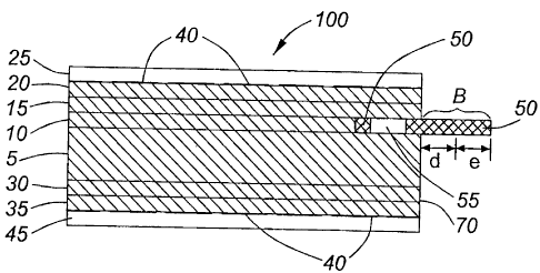
[00020] Referring to Figures 1 and 2, these drawings show, respectively, a
cross-
6
CA 02499912 2005-03-09
sectional view of a hard synthetic page 100 according to the invention and a
plan view
of an intermediate layer 120 thereof which provides a flexible component 50,
with a
flexible band, according to the invention. The hard synthetic page 100 is a
composite
laminate sheet made from a plurality of core material layers laminated
together, in this
embodiment the core material layers being layers 5, 10, 15, 20, 25, 30, 35 and
45.
Between the core material layers 15 and 5 an intermediate layer 120,
comprising the
flexible component 50, is provided. In this embodiment, the intermediate layer
120
includes a hard component 10 in addition to the flexible component 50. As
illustrated,
the component 10, positioned on the left-hand-side, is made of the hard core
material
that is laminated and is juxtaposed with component 50, positioned adjacent
thereto on
the right-hand-side, which is made of the flexible material. As may be best
seen by
Figure 2, the flexible material component 50 includes a plurality of spaced
apertures 55
along an inner edge 72 thereof and extends beyond an outer edge 70 of the
laminate
sheet 100 to provide a flexible band B that can by sewn into a security
booklet. As
shown, the flexible band B has a width equal to distances "d" plus "e".
[00021] The hard synthetic page 100 has the characteristic of a secure,
monolithic
structure and, as such, it is suitable for incorporation into a travel
document together
with the paper pages typically present that type of security booklet. It is a
multi-layer
laminate of the hard core material, produced as described herein, so as to
integrally
combine a flexible band material therein without any direct core-to-flexible
material
coupling. Advantageously, the flexible material is itself neither welded nor
glued and,
therefore, any material having the desired flexibility, pliability, etc. can
be selected for
use.
[00022] For use in a security booklet, the flexible material of component 50
should
be selected to be flexible, pliable and durable so that it may act as a hinge
without
breaking, tearing or otherwise becoming damaged over the expected period (e.g.
five
years) and manner of use of the booklet. The selected material for layer 50
should
preferably also be selected to be soft and thin so that it can be sewn to the
other pages
7
CA 02499912 2007-12-12
of the booklet in the usual manner using conventional book binding equipment.
[00023] Further, the material to be selected for layer 50 must have a higher
melting
temperature than that of the core laminate material used for layers 15 and 5
which
encase layer 50 so as to ensure that the flexible material does not melt to
either of
layers 15 and 5. Instead, when the core material layers are laminated, the
material of
layers 15 and 5 in the area above and below the apertures 55 of the flexible
material
layer 50 is caused to melt and flow together to bond within the area of the
apertures 55
and thereby encase the flexible material component 50. This is illustrated by
Figure 4.
At the time of laminating the core material layers, the adjacent core material
layer 10
also melts and bonds with the sandwich layers 15 and 5. As such, the flexible
material
layer 50, including the band B, becomes encased and integrally, securely
formed within
the hard synthetic sheet 100 and is secure and tamper resistant within that
structure.
Preferred materials for the flexible component 50 will maintain their form,
flexibility and
strength at the temperatures required to laminate the core material, examples
of which
include polyamide (i.e. nylon) and Melinex* brand polyester film supplied by
DuPont
Teijin Films. Although, several synthetic materials, such as polypropylene are
thin and
flexible, they may not be suitable where they are unable to maintain their
form during
heat lamination.
[00024] The hard synthetic page 100 is constructed of a plurality of layers of
material. For the embodiment shown by Figure 1, these are layers 25, 20, 15,
120
(comprising layers 10 and 50), 5, 30, 35 and 45, but it is to be understood by
the reader
that the invention is not limited to the illustrated exemplary embodiment and,
to the
contrary, may be implemented in numerous alternative forms using a different
number
and thicknesses of layers as may be suitably selected for a given application.
The
layers 25, 20, 15, 10, 5, 30, 35 and 45 of the illustrated embodiment are made
of the
same material, or sufficiently similar material (in terms of achieving the
required
lamination) and this material is referred to herein as the page core material.
For the
illustrated embodiment, this page core material is selected to be
polycarbonate. As
*Trademark 8
CA 02499912 2008-10-10
shown, layers 25 and 45 are clear and layers 20, 15, 10, 5, 30 and 35 are
white. The
material selected for layers 25 and 45 is MakrofollD* 6-2 brand laser-
engravable
polycabonate supplied by the Bayer Company. For layers 20, 15, 10, 5, 30 and
35 the
material selected is MakrofollD* 4-4. When laminated together (without
adhesive) at an
appropriate temperature, pressure, and time, as may be readily determined by
persons
skilled in the art, these core material layers form a core-to-core bond which
is secure
(meaning that any attempt to dissect the layers would be difficult and such
tampering
would be evident upon viewing the page) and durable.
[00025] Polycarbonate, used for the core material, provides good protection
against bending, impact and other stresses that the synthetic page 100 will
likely
encounter. However, it is to be understood by the reader that although
polycarbonate
is selected for use in the illustrated embodiment, the invention may,
alternatively, be
implemented using a range of other materials providing the desirable
characteristic of
hardness, durability, etc., including PVC (polyvinyl chloride) and PETG
(glycol modified
polyethylene terephthalate). If desired, for an alternative embodiment,
adhesives could
be used between the multiple layers forming the synthetic page 100 and, also,
dissimilar
materials (provided that such adhesives adhere to each such material) could be
used
for the page core material, but such alternatives are not desirable and would
be
expected to result in a synthetic page of lesser durability and security than
that of the
preferred embodiment produced by laminating page core layers of the same
material.
[00026] In the preferred embodiment, as shown by Figure 1, layers 20 and 35
include lithographic security printing 40. So, for this embodiment, the page
core
materials used forthese layers must be Iitho-printable i.e. such that good
quality security
printing is obtained, and the inks used for the printing must be able to
withstand the
temperatures required for laminating these materials to achieve core-to-core
bonding.
These layers 20 and 35 are security printed and are provided in sheets. The
outer
layers 25 and 45 are, optionally, included to form a protective overlay for
the security
printing on layers 20 and 35.
* Trade-mark 9
1
CA 02499912 2005-03-09
[00027] In the illustrated embodiment, layer 15 is included such that the
combined
thickness of layers 25, 20 and 15 provides sufficient strength to withstand
tearing when
any attempt is made to remove layer 15, whereby a combined thickness of 300
microns
is adopted for this embodiment. The illustrated use of two layers, 15, 20,
rather than
using one layer only of the combined thickness of the two layers, is a
preferred option
for this embodiment in order to reduce costs when the material of the layer
having
lithographic printing thereon is spoiled during the printing process.
[00028] The illustrated use of separate layers 5 and 30 as shown in Figures 1
and
3 is optional, for use when it is desirable to provide a combined layer that
can function
as an inlay for containing, for example, a contactless chip, chip module,
antenna and
attachments (not illustrated). For such applications the thicknesses of the
layers are
governed by the dimensions of the chip components and the inlay may be
provided by
an inlay manufacturer in sheets according to a preselected layout. If such an
inlay
configuration is not desired, the thickness of these layers may differ, and/or
the use of
one layer only in place of such separate layers 5, 30 may be adopted, as
appropriate
for the application, but for all applications each layer adopted for use is
comprised of the
core material and is laminated with the other core materials layers of sheet
100. A
further option that may be desired when using the illustrated inlay
configuration is to also
affix a thin layer of the same material to opposite sides of 5 and 30 during
the making
of such inlay.
[00029] The intermediate layer 120 of the exemplary embodiment is made of the
two components 10 and 50 shown in the drawings. The hard component 10
comprises
the core material of laminate sheet 100 such that a core-to-core bond is
achieved with
layers 15 and 5 during heat lamination. The flexible component 50 provides a
flexible
band B, in accordance with the invention, which is used to form a connection
between
the laminate sheet 100 and the other pages of the security booklet. Each of
the layers
and 50 are cut into strips as shown in Figure 3. The flexible material of
component
CA 02499912 2005-03-09
50 allows the band B to be connected to the booklet by way of sewing it into
the spine
of the booklet in the same manner used currently for paper or other synthetic
pages
such as heat seal laminates. As such, the material of component 50 is selected
so that
it is thin and pliable enough to be sewn with existing manufacturing
equipment, it bends
easily when the booklet is opened and closed, and it is durable enough to
withstand
both the sewing process and the various bends, pulls and other stresses that
it will
encounter over the life of the security booklet.
[00030] The flexible component 50 is connected to the core material layers in
the
following manner. Apertures 55 are cut or milled out of the flexible component
50 in the
area where the joinder with the core material is to occur, as shown best in
Figures 1 and
2. Flexible component 50 is placed between layers 15 and 5, as shown, and heat
lamination is undertaken so that the materials of layers 15 and 5 flow into
the cavities
of apertures 55 and form a strong core-to-core bond between layers 15 and 5.
The
shape of apertures 55 defined by bounds (b, g) and the distance (h) between
apertures
55, are selected so that an area of sufficient size to achieve that core-to-
core bonding
between layers 15 and 5 is provided and, at the same time, a sufficient amount
of the
material of the component 50 remains to be encased by that bonding of layers
15 and
to make it difficult to detach the component 50 from the laminate core. In the
illustrated exemplary embodiment the selected length (b) is 6.25 mm, the
selected
length (g) is 6.25 mm and the selected length (h) is 6.0 mm.
[00031] The distances (a, c, f) from the boundaries of the apertures to the
edges
of the flexible component 50 are selected so as to avoid any easy rupturing,
by stresses
applied to the band B, of the surface of any of layers 25, 20 and 15 and the
surface
areas of the component 50 material, between layers 15 and 50 and between
layers 50
and 5, are minimized because the laminate core material and the flexible band
material
do not laminate or otherwise securely affix to each other from the heat
lamination. In
the illustrated exemplary embodiment the selected length (a) is 1.75 mm, the
selected
length (c) is 1.75 mm and the selected length (f) is 6.0 mm (though the
manufacturing
11
CA 02499912 2005-03-09
of this embodiment can somewhat vary this length (f)).
[00032] The length (d) of flexible material of component 50 from the edge of
the
laminate sheet 100 to the spine (marked by "S" in Figure 2) is selected so
that the hard
laminate sheet 100 of core material cannot easily be bent against the flexible
band B to
thereby cause the connection of component 50 to rupture. In the illustrated
exemplary
embodiment the selected length (d) is 13.0 mm. The length (e) of flexibie
material of
component 50, forming the spine area thereof, is selected so as to minimize
the amount
of material of band B which extends from the spine on the other side of the
booklet. In
the illustrated exemplary embodiment the selected length (e) is also 13.0 mm.
[00033] The specific number of layers, and thicknesses therefor, to be
selected
according to the invention are not fixed and no specific layer configuration
(number
and/orthickness) is required to implement the invention. Forthe illustrated
embodiment
shown by the drawings, representing one example only, the following layer
thicknesses
are selected: layer 25 is 100 pm; layer 20 is 100 pm; layer 15 is 100 pm;
layer 10 is 100
pm; layer 50 is 100 pm; layers 5 and 30 (together forming one inlay
configuration in this
embodiment) are 430 pm; layer 35 is 100 pm and layer 45 is 50 pm.
[00034] In manufacture, layers 25 through 45 are gathered and layered in the
manner shown in Figure 3 such that the flexible component 50 extends outside
of the
stack of layers. The layers are heat welded to maintain their positioning for
heat
lamination. Then the layers are laminated together at appropriate temperature,
pressure and time amounts, as required to form a core-to-core bond of the core
materials of the laminate sheet. Depending on variables such as the overall
thickness
and the surface finish of layer materials, the temperature, pressure and times
used for
the sheet construction of the illustrated embodiment, of which the core
material is
polycarbonate (without adhesive), are about 190 C, 100 bar, and 20 minutes,
respectively, over a sheet size of 364 x 582 mm. The resulting laminated sheet
is then
cut to suitably sized individual sheets for security booklet manufacture by
which the
12
CA 02499912 2005-03-09
sheet is placed in the appropriate position of pages of the security booklet
at sewing
stations and is sewn together with the other pages of the booklet. Following
this, the
remaining steps in constructing the security booklet are performed in normal
manner,
including applying the covers and die-cutting.
[00035] Although stated already, it is hereby emphasized that the examples
specified above, with reference to the particulars of the illustrated
embodiment, of
materials that may be selected for use as the laminate core material and
flexible band
material, are not intended to be comprehensive or limiting in any manner
whatsoever,
and other material combinations may be selected for use and satisfy the
aforesaid
functional requirements of those materials. Similarly, a variety of different
layer
configurations, material thicknesses and lengths, and relative band and
aperture
geometries may be selected for successful (effective) use without limitation
to any
exemplary figures disclosed herein with reference only to the exemplary
illustrated
embodiment.
[00036] Persons skilled in the field of security printing will be readily able
to apply
the present invention to implement various applications of the same.
Consequently, it
is to be understood that the particular embodiment described herein by way of
illustration is not intended to limit the scope of the invention claimed
herein by the
inventors and defined by the appended claims.
13