Note: Descriptions are shown in the official language in which they were submitted.
CA 02500191 2004-11-29
WO 02/097411 PCT/IS02/00011
APPARATUS AND METHOD FOR MICROWAVE DETERMINATION OF AT LEAST
ONE PHYSICAL PARAMETER OF A SUBSTANCE
This application claims priority from Icelandic application No. 5960 and US
provisional application
No.60/294,249.
Field of the invention
The present invention concerns a method and apparatus for determining at (east
one
physical parameter of an object by means of transmitting microwaves towards
the
object and analysing the co-polar and cross-polar transmitted and reflected
microwaves.
Background of the invention
It is well known that during processing of a variety of products such as wood,
tobacco
and food the moisture content in the product plays an important role before
the
product enters the final stage in the production.
When the moisture content is measured by using microwave radiation, the
microwaves interact with the water molecules in the substance being measured.
Due
to the dipole character of the water molecule, the microwave fields interact
with the
molecules resulting in a rotational and translational motion of the molecules
causing
heat absorption of the incident energy. By measuring the attenuation (loss of
energy)
of the microwaves along with the phase skiff (loss of velocity) of the
microwaves the
moisture content of the material can be accurately determined. This is
typically done
by transforming the output signal to an electrical signal. The attenuation and
phase
shift within a material can be used to calculate the dielectric properties of
that
material. The dielectric properties of a material are usually expressed by the
relative
complex permittivity, a = E' + je" , where s° is the dielectric
constant that represents
the ability of a material to store electric energy, and a°° is
the loss factor representing
the toss of electric field energy in the material. By knowing both E' and
~°' one can
calculate water content and density of the material according to published
formulae.
Furthermore, other physical parameters such as fat, protein and salt can be
determined for example by using more than one frequency and isolating the
absorption effects due to water and absorption due to the presence of salt
ions which
are governed by the difference in the frequency dependence of the two loss
CA 02500191 2004-11-29
WO 02/097411 PCT/IS02/00011
mechanisms. By doing repeated analysis with the device and by comparing
results
obtained by using conventional methods, calibration can be achieved.
Hitherto known methods using microwaves generally only measure moisture
content
but not other physical parameters such as fat, protein and salt. For example,
no
device has been made to measure fat content using non-contact microwave
techniques. A hand held device has been made that estimates fat content using
microwaves. However, the device needs to be in firm contact with the substance
to
be measured and actually measures the moisture content. The device is
precalibrated and calculates the fat content from the measured moisture
content.
Other systems and methods have been developed for measuring the moisture
content of material. One is to use a hand held instrument, similar to the one
mentioned above, a so called "stripline" sensor. The instrument is placed on
the
material in such a way that the stripline is in close contact with the
material.
Microwaves are then generated and fed along the stripline, and the attenuation
is
measured in the stripline. The attenuation or loss is then converted to water
content.
This method is a surface measurement. To obtain overall moisture content in
bulk
material, it is necessary to measure at several places, and turn the object
around.
The average value is then used as an indicator.
In another device the material is placed between the transmitting and
receiving
antennas of a microwave transmission system and by comparing the output signal
from the material with the source signal the material properties can be
deduced.
In yet another device material, US patent no. 4,578,998, there is a
description of a
microwave system using different polarisation of signals. Two radiators are
used to
measure across a sheet material by utilizing two different polarisations so
that signal
interchange between them is avoided. The polarisation is in other words used
to
distinguish between radiators.
The problem with US patent no. 4,578,998 is that the measured signal comprises
both the attenuation through the material and also reflections from microwaves
bouncing off surrounding material, which is not being examined. This will
introduce
errors into the result.
CA 02500191 2004-11-29
WO 02/097411 PCT/IS02/00011
The disadvantage of using the hand held contacting instrument is that it is a
surface
measurement of a bulk material. Therefore it is time consuming to obtain a
measurement for the material as a whole due to the fact that one has to
measure on
various spots around the material and also due to the inconvenience of having
a
human operating the instrument by placing the sensor in contact with the
material
while measuring it: This can cause errors since people will never operate the
instrument in exactly the same way.
General description of the invention
It is an object of the present invention to improve the above mentioned
methods by
providing a method and an apparatus to measure at least one physical parameter
of
a substance, such as moisture and fat content of bulk material. This is done
by
utilizing the polarisation to create a transmission path through the sample,
wherein a
microwave beam is transmitted through the material to be measured and only a
reflection of a predetermined polarity of the transmitted waves is detected.
This has
the advantage the only the signal that has travelled through the material is
measured.
This is accomplished by providing a polarising plate so that only cross-
polarised
microwaves, which pass through the substance is detected and co-polar
reflections
from surrounding structures are excluded. This increases therefore the
sensitivity and
accuracy of the measurement. Accordingly, only those waves are received that
have
bounced off the polarising plate after passing through the substance being
measured. When the system is set up to detect cross-polar reflections it can
be
ensured that the measured microwaves have passed through the object twice
before
being detected. When the system is set up to detect co-polar reflections the
distance
of the surface of the material from the aperture of the receive antenna can be
determined and this can be related to the depth of the material by comparing
with co-
polar reflections when no material is present.
According to the first aspect the present invention relates to an apparatus
for
determining at least one physical parameter of an object by means of
transmitting
microwaves towards the object and analysing the reflected microwaves, said
apparatus comprising:
~ a source for generating a time dependent electrical signals,
CA 02500191 2004-11-29
WO 02/097411 PCT/IS02/00011
~ a transmitter positioned in proximity to the object for converting the time
dependent electrical signals to microwaves and transmitting the microwaves
towards the object,
~ a polarizes positioned adjacent to the object and opposite to the
transmitter
for rotating at least part of the polarisation of the transmitted waves and
reflecting a predetermined polarity of the transmitted waves,
~ a receiver positioned opposite to the object with respect to the polarizes
for
receiving the reflected microwaves of predetermined polarity and converting
them into an electrical signal, and
~ a computer system for utilizing the electrical signal for calculating the at
least
one physical parameter of the object.
Further, control electronics is preferably provided to control the source. The
polarizes
may be a plate with a plurality of parallel metallic wires positioned in the
horizontal
plane of the polarisation plate for rotating at least a part of the
transmitted waves.
These wires can be supported by a non-reflecting medium such as a plastic
material.
The bottom layer of the polarization plate is a reflecting material such as a
metallic
plate. As the microwaves hits the polarisation plate part of them hits the
wires that
rotate the polarisation and a part passes between the wires through the
supporting
material until it is reflected from the bottom plate. The bottom plate
reflects the
microwaves according to the law of reflection, wherein a part of these
reflected
microwaves hit the wires that rotate the polarisation. With a properly
thickness of the
polarisation plate, i.e. interval between the wires and the bottom plate, the
"second"
polarisation can be the same as the "first" polarisation. Preferably, this
interval is 1/4
~,, where 7~ is the wavelength of the microwaves, or generally (1/4+n) 7~ with
n as an
integer. This is however typically the case when air is between the wires and
the
reflecting plate. However, this thickness ratio is different when there is a
material
between the wires and the reflecting plate, and depends on the dielectric
properties
of the material. The rotated polarisation is received with a receiver that
converts the
microwaves to an electrical signal. This polarisation of this received
microwave can
for example be 90° rotated with respect to the transmitted microwaves,
which can be
linearly polarised and/or circular polarized. The receiver can for example be
an
antenna or a dipole.
CA 02500191 2004-11-29
WO 02/097411 PCT/IS02/00011
The frequency of the time dependent electrical source signal depends on
whether
only one parameter is measured, such as moisture, or more parameters are
measured, such as moisture and salinity. This is due to the different
characteristic of
the water and salinity molecules and their resonance frequency. In one
embodiment
the time dependent electrical signal has a frequency in a sequential cyclic,
i.e. first
the frequency is for measuring the moisture and the second, different
frequency, is
for measuring the salinity. Therefore the time dependent electromagnetic field
has at
least one frequency.
For determining at least one physical parameter of the object, which can be
the
moisture content and/or the density of the object, it may be useful to use a
reference
channel. In one embodiment the apparatus is provided with a coupler for
dividing the
electrical signal between the transmitter which can be a transmitting antenna
and the
receiver, wherein the part of the electrical signal directed towards the
receiver passes
trough a reference channel and is used as a reference signal. Preferably half
of the
source signal passes through the reference channel and the other half to the
transmitting antenna.
The measurements on the object can be as the object is in a rest position or
as the
object is being conveyed by a conveying means such as a conveyor belt. The
transmitting and the receiving antennas will normally be in close proximity at
a
suitable position above the object with their radiation patterns directed at
the object.
For attenuation measurements the antennas are with respect to each other
orthogonally polarized.
Furthermore, to measure the permittivity constant of the material, it is
important to be
able to determine the thickness of the material. One way of measuring this is
by
implementing a second receiving antenna positioned above to the object with
respect
to the polarizer and close to the transmitting antenna. The co-polar signal
therefore
measures the difference in distance when no material is present and when
material is
present. Preferably, the polarity of the received microwave is in this case
the same
as the transmitting microwaves. It is also possible to use ultrasound for the
same
purpose.
A further aspect of the present invention is to provide a method for
determining at
least one physical parameter of an object by means of transmitting a microwave
CA 02500191 2004-11-29
WO 02/097411 PCT/IS02/00011
towards the object and measuring the reflection, said method comprising the
steps
of:
~ generating a time dependent first electrical signal and converting at least
part
of the first electrical signal to microwaves,
~ transmitting the microwaves towards the object,
~ reflecting the transmitted microwaves by a polarizer positioned adjacent to
the
object and opposite the transmitter wherein at least part of the polarisation
of
the reflecting microwaves is rotated,
~ receiving the rotated part of the reflected microwaves from the polarizer
with a
receiver positioned opposite to the object and converting the received part of
the transmitted wave into an second electrical signal, and
~ analysing the second electrical signal and determining at least one physical
parameter.
In one embodiment the time dependent electrical signal from the source is
split in
two, partly passing through a reference channel and partly passing from the
polarising plate to a receiving means, and thereafter the two signals are
added again.
The summed signal is used as a reference signal with a reference phase and a
reference level, for example when no material is present on the polarising
plate. Any
deviation from this reference phase and reference level when an object is
placed on
the polarizes is used to determine relative complex permittivity of the
object. A shift in
the reference phase or frequency can be used to calculate the dielectric
constant s',
and a shift in the reference level can be used to calculate the loss factor ~"
of the
object. Another parameter which is important when calculating s' and ~" is
thickness
of material which microwaves travel through. This parameter can be determined
for
example by using a second receiving means positioned opposite to the object
with
respect to the polarizes. The second receiving means would preferably be
adjusted
so that it detects microwaves of the same polarity as the transmitted
microwaves.
Therefore the part of the microwaves that is reflected from the object is
determined
and compared to a reference signal, for example a signal without any object,
and the
phase shift from this reference signal is used to determine the height of the
object. By
CA 02500191 2004-11-29
WO 02/097411 PCT/IS02/00011
7
knowing the distance betweenthe aperture and the polarising plate, and the
angle of
radiation from the transmitting horn, the effective measurement area can be
determined. Together with the thickness, the volume is thus calculated.
The transmitted microwaves can be linear polarized and the polarisation part
of the
reflected wave that the receiving means detects is preferably 90°
polarized with
respect to the transmitted microwave. This is to ensure that only the part of
the
transmitted waves which have passed through the entire object is detected,
wherein
the polarizes is located under the object and therefore the microwaves with
this
polarisation must pass through the object. One way of measuring the phase
change
and attenuation change in a material is by using a reference channel. The sum
of
the signal from the reference channel and the signal reflecting of the
polarizes, will be
zero, with the aid of an adjustable attenuator and phase shifter in the
reference
channel when no material is present. Rather than linear polarisation of the
microwaves it may be possible to use circular polarisation, for example in
cases
where fibres in the material are likely to be predominantly in one direction,
for
example perpenticular to the transmit horn.
Furthermore, the moisture content can be used to determine the fat
concentration of
an object such as fish, where the buoyancy is known and constant, and
therefore the
relationship between fat and water in the body is established by empirical
formula.
This could be achieved by using historic data.
Detailed description
in the following the present invention, and in particular preferred
embodiments
thereof, will be described in greater details in connection with the
accompanying
drawings in which,
FIG. 1 is a flow chart showing how one embodiment can be used with the method
of
the present invention to measure moisture content.
FIGS. 2a and 2b are schematic drawings of one embodiment of an apparatus,
which
can be used with the method of the present invention.
CA 02500191 2004-11-29
WO 02/097411 PCT/IS02/00011
FIG. 3 is a schematic drawing of a second embodiment that can be used with the
present invention for measuring moisture content.Furthermore, this embodiment
also
measures the depth and hence the density of the object or substance being
measured.
FIG. 4 is a graph showing samples of the electrical response to the presence
of an
object or substance within the transmitted beam, which is used to calculate
the
density of the measured object and the wet mass of the measured object.
FIG. 5 shows one embodiment of the polarises.
FIG. 6 shows results from experiments with the apparatus
FIG. 1 is a flow chart showing how one embodiment of apparatus can be used
with
the method of the present invention to measure moisture content.
The apparatus includes a microwave radiation source 1, shown to the left of
the
coupler 2. In a preferred embodiment the microwave radiation source 1 is a
swept
source that sequentially transmits microwaves with a frequency which changes
preferably linearly with time over a specified frequency bandwidth. . The
source (or
sources) may be arranged to transmit more than one centre frequency. The swept
source 1 receives a signal from the switch 15 before sending a signal to the
coupler
2. The switch 15 determines which centre frequency is transmitted.
The signal from the swept source 1, once amplified to an appropriate level, is
then
divided at the coupler 2, with part of the signal passing through a reference
channel
to the receiver 7, while the remaining signal passes to the transmit antenna 4
in the
measurement channel. Preferably the signal that goes to the two different
direction
are equal, each part being exactly 50% of the original signal.
It will be appreciated that the sample being measured can be replaced with a
continuous flow of bulk material without departing from the principles of the
present
invention. For the purpose of this illustration the apparatus will be
described only
with a single sample to be measured.
The microwaves are directed at the sample by means such as transmitting
antenna
4. Alternatively, a planar antenna can be used for the same purpose.
CA 02500191 2004-11-29
WO 02/097411 PCT/IS02/00011
The source signal 10a is a very high frequency microwave signal which is
frequency
modulated by linearly sweeping the source oscillator from a frequency just
below the
centre frequency to a frequency just above it over a predetermined bandwidth.
The
preferred centre frequency for the source signal depends on the nature of the
sample
14 and the number of frequencies depends on the number of physical parameters
to
be measured, such as moisture, salt or protein.
The source signal 10a passes through the sample 14, hits the polariser 5 and
is
reflected back. As the source signal 10a has passed through the sample it is
both
attenuated and slowed. The extent of this attenuation is determined mostly by
the
loss factor ~" of the material of the sample 14 encountered by the source
signal.
The degree to which the source signal is slowed is predominantly determined by
the
dielectric constant s' of the material 14.
As the source signal 10a hits the polariser 5 the polariser 5 changes the
polarisation
of the signal to that of the receiver antenna 6. The transmit antenna 4 and
the
receiver antenna 6 are essentially identical except that they will be
orthogonally
polarised. This means that any reflections off the sample, conveyer belt or
conveyer
belt superstructure or any surroundings, plus any direct radiation from the
transmit
antenna 4 to the receiver antenna 6, will not be identified by the receiver 7
since
these signals will not have the correct polarisation for entry into the
receive antenna
6. Once the system is calibrated the receiver 7 will detect, in principle,
only those
electrical changes in the measurement signal due to the presence of a sample
14 in
the system.
The sample 14 will introduce additional phase shift and attenuation in the
measurement channel. In a preferred embodiment there is only one receiving
antenna but it will be appreciated that there can be more than one receiving
antenna.
In one embodiment, a frequency mixer is used in both reference and measurement
channels to measure the phase difference. In another embodiment, the reference
signal 8a goes to an attenuator and phase shifter 3. The attenuator and phase
shifter 3 will be set during calibration so that this channel replicates the
electrical
characteristics of the measurement channel in the absence of a sample 14 or in
the
presence of a sample of known characteristics.
The receiver 7 adds the reference signal 8b and the measuring signal 10b in
anti-
phase at the receiver input. The inserted phase shift and the attenuation in
the
CA 02500191 2004-11-29
WO 02/097411 PCT/IS02/00011
reference channel which produces a null signal at the receiver is recorded.
The
recorded phase shi ft and the attenuation is sent to the processor where the
calculation of physical parameters such as moisture is done.
In an apparatus where more than one frequency is used, the method is the same
as
above and the switch 15 then switches between different frequencies.
The description above is a description of one embodiment. Generally there are
four
main ways to perform the measurement:
10 1. The simplest embodiment would be to use a swept oscillator 1 together
with
both an electrically controllable (programmable) phase shifter and attenuator
3 in the reference channel. In this embodiment the receiver controlled phase
shifter and attenuator 3 are adjusted until the added signals at the receiver
input are in 'exact' antiphase producing a 'null' input signal 4 in Fig.4, at
the
calibration frequency. The recorded change in both attenuation and phase
shift when sample 14 is present is sent to the processor.
2. The source 1 is un-swept but frequency controllable and the reference
channel contains only an electrically controllable attenuator 3. In this case
the
oscillator frequency and the attenuator 3 are adjusted to produce a null at
the
receiver 7. The recorded change in frequency and attenuation are passed to
the processor.
3. A swept frequency source 3 is used which permits the frequency responses
shown in Fig. 4 to be produced at the receiver. The receiver electronics are
more complicated and require to be able to record the change in shape of this
response which is an indication of the phase change and attenuation change
due to the substance being measured. In this case the reference
channel°s
programmable phase shifter and attenuator are not needed since the more
sophisticated electronics are providing the requisite phase shift and
attenuation information. However, the manually adjusted attenuator and
phase shifter 17 in Fig.3 will still be present to calibrate the system to
achieve
an exact antiphase or null input signal 26 in Fig.4, at a certain frequency,
when no sample is present.
4. The source 1 is unswept, and both the attenuation change and the phase
shift
change caused by the insertion of a sample, is determined directly through
separate cross-polar receive channels, one for amplitude and the other for
CA 02500191 2004-11-29
WO 02/097411 PCT/IS02/00011
11
phase. In the amplitude channel, a rectifying diode is used to provide a d.c.
signal level which is a measure of the sample attenuation. In the phase
channel, a double balanced frequency mixer is used to provide an I.F. (d.c.)
signs! level which is a measure of the phase change caused by the sample.
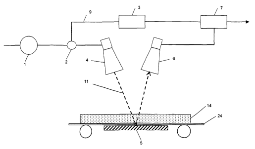
FIGS. 2a and 2b are schematic drawings of one embodiment of the present
invention
demonstrating a very simple version of an apparatus. The microwave source
lwhich
can be a swept source generates a timed dependent electrical signal, where a
part of
the signal is divided at the coupler 2 where part of the signal is used as
reference
signal 9, while the remaining signal passes to the transmit antenna 4 where
part of it
is reflected from the polariser 5 and going through the object 14. This is
called the
measurement signal 11.
FIG. 3 is a schematic drawing of a second exemplary embodiment of an apparatus
that can be used with the present invention. This apparatus measures similar
as the
apparatus in Fig. 2 the moisture and salt content of a sample (tobacco),
wherein the
sample can be in a rest position or being conveyed on a conveyor belt.
This apparatus uses two frequencies since it is measuring two different
physical
parameters, moisture and salt content. Therefore the switch 15 switches
between 8
GHz and 12 GHz after receiving a signal from the receiver 7. Other frequencies
can
be used for the same results.
The apparatus includes a microwave radiation source 1. The swept source 1
receives a signal from the switch 15 before sending a signal to the coupler 2.
The signal from the swept source 1, once amplified to an appropriate level, is
then
divided at the coupler 2, with part going as a reference signal 8a through a
reference
channel to the receiver 7, while the remaining signal passes to the transmit
antenna
4 as the measurement signal 10a. The signals that go to the two different
direction
are ideally equal, each part being exactly 50% of the original signal.
The microwaves are directed at the sample and are transmitted from the
transmit
antenna 4. The source 1 is a very high frequency microwave oscillator the
frequency
of which is changed linearly with time in a repetitive manner over a
prescribed
bandwidth.
CA 02500191 2004-11-29
WO 02/097411 PCT/IS02/00011
12 ..
A part of the transmitted signal 11 passes through tha sample 14, hits the
polariser
and is reelected back. Another part of the transmitted signal 25 is reflected
as the
signal hits the sample. That part is received by the co-polarised receive
antenna 19
and is used to measure the thickness of the sample 14 by detecting the phase
shift of
the first reflection. The part that passes through the sample 14 and hits the
polariser
is received, after reflection and change in polarisation, by the~transverse
polarised
receive antenna 6.
The reference signal 8a goes to a manually adjusted attenuator and phase
shifter 17
I0 and then to a programmable/variable attenuator and phase shifter 18. The
manually
adjusted attenuator and phase shifter 17 is used to calibrate the signal once
the
apparatus is set up so as the summed signal is 0 at a certain frequency in the
frequency sweep, when there is no object present. When a sample is present, it
increases the attenuation and phase shift in the microwaves in the measurement
channel and the signal 10b is weaker as it goes into antenna 6. Receiver 7
then
sends a signal to adjust the programmable/variable attenuator and phase
shifter 18
to achieve a summed signal of nul again. The amount of adjustments is recorded
as
the measurement values of attenuation and phase of the sample.
An infra-red thermometer 20 measures the temperature of the sample 14 and
sends
a signal to the receiver so that measurements of the relative complex
permittivity can
be corrected for different temperatures.
The receiver 7 adds the reference signal 8b and the measuring signal 10b in
anti-
phase. When phase shift and attenuation 18 is adjusted correctly, a null is
detected,
meaning that attenuation in 8b is the same as in 10b. The phase shift and the
attenuation in the the reference channel are then recorded. The detected phase
shift
and the attenuation is sent to the processor where the calculation and
conversion of
values into meaningful information is done.
FIG. 4 is a graph showing an example of an electrical signal from receiver 7
used to
calculate the ~' and E" of a sample. The x-axis represents the frequency sweep
of
the source and the y-axis shows the strength of the signal. At first, no
sample is
present and the system is tuned to give response 26. When sample is present,
attenuation of transmitted microwaves increases due to loss in the material,
and
there will be a phase change. Since the signal is unchanged in the reference
channel, the sum of the reference signal and the measurement signal changes
when
CA 02500191 2004-11-29
WO 02/097411 PCT/IS02/00011
13
sample is present, and this is shown by response curve 27. The difference in
horizontal direction represents phase change and differency in vertical
direction
represents attenuation change due to the sample, and these parameters are used
to
calculate s' and E" according to published formulae.
Both the wet-mass and the density determination can be based on historic data
depending on the object, which can for example be a tobacco, wood or corn.
Each of
these objects may have their own relation between the phase shift and
attenuation
and the actual moisture content and density. Rather than using formulae, one
could
choose to collect data from the apparatus and fit to the actual values of
moisture and
density.
In Fig. 4 the curve 26 shows a measured signal when there is no sample being
measured, as in Fig. 2a. In this case the measured signal is the same as the
reference signal, but with different polarisation. Thus, the sum of the
reference signal
and the measured signal is then 0 at a certain frequency in the sweep. The
reference value is then 0 for no moisture present.
The measuring curve 27 shows when the signal goes through a sample with
moisture. !n this case the sample reduces or attenuates the signal by 50%.
Since
the reference signal is unchanged, the sum of the reference signal and the
measured
signal is changed by 50% in the vertical direction, which is the attenuation
axis. If the
sample was pure water, absorbing all microwaves, measurement signal would be
attenuated to nothing, and only reference signal would be received, giving a
straight
line at the attenuation level of the reference signal.
Furthermore, the curve 27 represents a phase shift in the microwaves for a
frequency
sweep, which can be seen by the location of the minima of the signal, which
has
moved to the left from fo to f,. This phase shift is as mentioned before used
to
calculate the density of the sample.
From calculating density by using the relative complex permittivity, using the
formula
for density p=(mWe~+md~,)~V and by knowing the wet mass mWet the dry mass can
be
calculated if the volume of the object is known. As shown in Fig. 3, the
volume can
be estimated by means of using the co-polarised receive antenna 19 to measure
the
thickness of the sample 14, which can be registered periodically. If the
object is being
CA 02500191 2004-11-29
WO 02/097411 PCT/IS02/00011
14
transported on a conveyer belt with a constant speed, the object can be
divided into
parts with a fixed height and different thickness.
FIG. 5 shows one embodiment of the polariser, comprised of parallel metallic
wires
28 positioned in the horizontal plane of the polarisation plate for rotating
at least a
part of the transmitted waves. These wires can be supported by a non-
reflecting
medium 29 such as a plastic material. The bottom layer of the polarization
plate can
be a reflecting material such as a metallic plate 30. As the microwaves hits
the
polarisation plate part of them hits the wires that rotate the polarisation
and a part
passes between the wires through the supporting material until it is reflected
from the
bottom plate 30. Having the side of the polarisation plate positioned parallel
to the
line between the transmit antenna 4 and the receive antenna 6 and the two
45°
angles 31, 32 equal ensures a 90° rotation in the polarisation of both
the incoming
microwaves from the transmit antenna 4 and the microwaves reflected from the
bottom plate 30 that hit the metallic wires 28 on the way out of the non
reflected
medium 29.
The invention is further illustrated by the following example, which is not
intended to
be limiting in any way.
Example.
The following example is based on a experiment that was carried out on 9
samples of
tea leaves, where each sample was around 100g, and each with different
moisture
content, from 5% moisture to 20% moisture. Two swept frequencies were used,
one
around 8GHz and one around 12GHz. Attenuation was measured in the samples,
but not the phase change. The experiment shows that there was a linear
relationship
between attenuation and actual moisture content of the sample, as can be seen
in
Fig. 6. The correlation coefficient was high, 0.9914 for the 8GHz and 0.9789
for the
12GHz. The correlation coefficient is a factor from 0 to 1, which represents
how well
the data points fall into a fitted line.