Note: Descriptions are shown in the official language in which they were submitted.
CA 02500237 2005-03-24
WO 2004/030795 PCT/EP2003/010753
PROCESS AND PLANT FOR ULTRAPURIFYING FUMES OR GASES WITH
TOTAL RECOVERY OF THE RESULTANT POLLUTANTS
The present invention relates to a process and a plant for ultrapurifying
fumes or gases with total recovery of the resultant pollutants.
The atmosphere is well known to contain a considerable level of pollutant
fumes and gases produced by ex-waste dumps (biogas), gasifiers, power
stations,
waste incinerators, etc. and containing micropollutants consisting mainly of
particles of diameter less than 1 Nm (fine particulate) which have been shown
by
epidemiological studies to cause illness and death.
The most obvious and dangerous example is that of waste incinerators,
which generally consist of a large air-fed combustion chamber operating at
about
900°C followed by a small post-combustion chamber operating at about
1200°C,
and are able to transform the waste feed into mainly fine particles, into C02,
into
H20, etc.
Subsequent purification of the fumes with filters, also known as dry
purification, is unable to effectively remove micropollutants in particular,
whereas
wet purification, which would be more effective, can no longer be used because
discharge of polluted effluent water into the environment is forbidden.
Consequently although current waste incinerators solve the general
problem of thermal destruction, they have not yet satisfactorily solved the
problem
of eliminating micropollutants. In particular, the fumes emitted by an
incinerator
contain dangerous micropollutants originating essentially from two sources:
metals
and organochlorine compounds (dioxins and furans). These latter are difficult
to
remove as only a small percentage (about 20%) becomes attached to dust or
other easily removable solid particles present in the fumes, whereas the
remainder are in the vapour state (aerosol) and particularly dangerous because
on
CA 02500237 2005-03-24
WO 2004/030795 PCT/EP2003/010753
-2-
coming into contact with water or other liquids they are not removed, but
instead
are transported by them.
In particular the organochlorine compounds constitute very dangerous
environmental pollutants as they are able to develop a teratogenic and
carcinogenic activity and in addition harm the immune, endocrinic and
reproductive systems. They are also bioaccumulable, i.e. they are able to
accumulate along the alimentary chain, becoming always more dangerous with
time.
Because of these serious problems which such pollutants are able to
cause, the problem exists of removing them to the greatest possible extent,
the
object of the present invention therefore being to propose a method and plant
for
use downstream for example of any dry purification plant, to solve this
problem.
Another object is to remove from gases, prior to their use, any pollutants
which result in corrosion, wear, blockage, incrustation and other highly
damaging
consequences.
The aforesaid problem is solved according to the invention by a process for
ultrapurifying fumes or gases with total recovery of the resultant pollutants,
as
described in claim 1.
The invention also foresees a plant for implementing the process as
described in claim 32.
A preferred embodiment of the present invention is described in detail
hereinafter with reference to the accompanying drawings, in which:
Figure 1 shows schematically a plant for implementing the process of the
invention, and
CA 02500237 2005-03-24
WO 2004/030795 PCT/EP2003/010753
-3-
Figure 2 shows a block diagram of the operation of the plant connected to
external purification and gasification plants integrated with a system of
fuel cells.
As can be seen from the figures, the ultrapurification plant of the invention
is installed downstream of any purifier, for example of traditional type,
which uses
dry purification systems, possibly associated with equipment, for example a
scrubber (not shown), to reduce the fume temperature to ambient (about 20-
30°C).
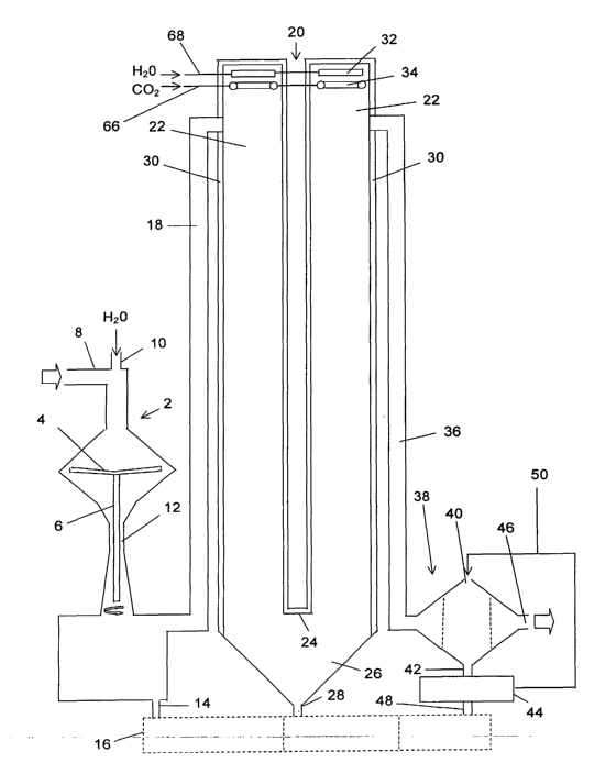
In its essential lines it comprises a washer 2, consisting essentially of a
vessel of double frusto-conical shape, the interior of which contains, at the
level of
the connection between the two major bases, a slightly upwardly concave plate
4
supported by a shaft 6 rotatable about its vertical axis at high speed,
preferably
not less than 1000 r.p.m.
The top of the vessel forming the water 2 is connected via a conduit 8 to
the scrubber from which the fumes or gases to be treated originate, and via
another short conduit 10 to the water jet feed at a temperature of about
4°C.
The lower part of the double-cone vessel 2 presents a constriction 12 able
to determine a venturi effect, below this it being connected via a conduit 14
to a
traditional water purifier 16. The washer is also connected via another
conduit 18
to a snow wash chamber 20 (snow producer), fed at the top with unpolluted
water.
The snow producer consists essentially of two side-by-side cylindrical
vessels 22 of vertical axis connected together at their lower end by a
horizontal
conduit 24 having a conical lower part 26 and provided at its lowest point
with a
discharge conduit 28 towards the water purifier 16. Each cylinder 22 comprises
a
heat-insulating covering 30 on its outer surface and is provided upperly,
below its
CA 02500237 2005-03-24
WO 2004/030795 PCT/EP2003/010753
-4-
roof, with a shower disc 32 fed by a conduit 68 for feeding unpolluted water.
In a
position below each shower disc 32 there is provided a pertorated ring 34 fed
by a
conduit 66 for feeding C02 at a temperature substantially less than
0°C.
One of the two cylinders 22 receives in its upper part, a short distance from
its upper edge, the conduit 18 connected to the washer 2, the other cylinder
22
receiving in its upper part a conduit 36 connected to an activated carbon
filter 38.
This filter 38 consists of a vessel provided not only with the lateral
connection opening to the conduit 38 for entry of the fume or gas stream, but
also
with an upper opening 40 for activated carbon entry, a lower discharge conduit
42
towards an underlying dryer 44, and a lateral opening 46 for discharging the
completely purified fumes or gases.
From the activated carbon dryer 44 there extends a conduit 48 for
discharging to the water purifier 16 the water which is generated during the
activated carbon drying process. Traditional conveyors, indicated
schematically in
the drawings by a conveying line 50, are also provided for transferring the
dried
activated carbon from the dryer 44 to the upper opening 40 of the filter 38.
Due to the different features of pollution of the waters coming out from the
washer 2, snow wash chamber 20 and dryer 44, it may be foreseen that the
purifier 16 consists of several different purifiers, each suitable to treat
the above
polluted waters in a more reliable way.
As stated, in the plant of the invention not only the discharge conduit 14
from the washer 2 but also the discharge conduit 28 from the snow producer 20
and the discharge conduit 48 from the activated carbon dryer 44 are connected
to
the water purifier 16, which for example comprises an evaporator providing
CA 02500237 2005-03-24
WO 2004/030795 PCT/EP2003/010753
-5-
purified exit steam along a conduit 52 and resultant polluted water along
another
conduit 54.
The water purifier 16 is connected by the conduit 54 to a gasifier 56,
consisting advantageously of the machine the subject of EP-B1-0292987,
entitled
"Method and machine for transforming pollutant or waste combustible materials
into clean energy and usable products", able to dissociate the water and
recover
the hydrogen.
The conduit 52 leaving the purifier 16 enters a heat exchanger 58 and
leaves as the conduit 10, which feeds the washer 2 with ice-cold water.
The gasifier 56 is connected via a conduit 60 to a fuel cell system 62 for its
feeding with H2 and via another conduit 64 to the heat exchanger 58 for its
feeding
with liquid C02, and from there, via the conduit 66, to the perforated rings
34 of
the cylinders 22 of the snow producer 20.
The fuel cell system 62 is connected via the conduit 68 to the sprinkler
discs 32 of the cylinders 22 of the snow producer 20, for its feeding with
unpolluted water.
The plant of the invention is also provided with a plurality of systems for
the
control, monitoring and adjustment of all the operative parameters, in
particular of
r
the fluid temperatures and flow rates. As these systems can be considered
traditional and hence within the capacity of the expert of the art, they are
not
further described.
The aforedescribed plant operates in the following manner:
the fumes and gases to be treated and from which macropollutants have
already been removed are fed into the washer 2, together with the jet of ice-
cold
water originating from the heat exchanger 58 and fed from above via the
conduit
CA 02500237 2005-03-24
WO 2004/030795 PCT/EP2003/010753
-6-
10. Within the washer 2 the water strikes the plate 4 which, by virtue of its
rotation, propels it at high speed by centrifugal effect against the facing
lateral wall
of the washer, this wall being grazed internally by the fumes or gases
containing
the micropollutants.
The effect of the hurling of said fumes or gases against the wall of the
washer 2 by the water flow, which is at its maximum density, combined with the
reduction in the cross-section of their passage through the annular gap
bounded
by the rotating plate 4 and said wall of the washer 2, causes the water to
incorporate a large part of the pollutants. This incorporation is facilitated
if the
angle formed by the direction of said centrifugal water jet and the fume or
gas flow
direction is less than 90°.
The subsequent annular constriction 16 traversed by the water/fume or gas
mixture pressurizes the system by the venturi effect, to enhance this
incorporation.
The resultant polluted water is discharged from the washer 2 through the
conduit 14 and transferred to the purifier 16, where it is treated.
The thus pretreated fumes or gases containing the micropollutants in a
considerably smaller quantity leave the washer 2 and pass through the conduit
18
to enter the snow producer 20. Here, on encountering the flow of cold C02
originating from the heat exchanger 58 and fed through the conduit 66 into the
snow producer 20 from above, the unpolluted water, obtained by hydrogen
combustion in the fuel cells 62, in accordance with the already stated EP-B1-
0292987, is transformed into snow flakes by virtue of the low temperature of
said
C02. These, while descending along the two cylinder vessels 22 forming said
snow producer, encounter the stream of fumes or gases in co-current and in
counter-current along the labyrinth path, to pick up the water containing the
CA 02500237 2005-03-24
WO 2004/030795 PCT/EP2003/010753
pollutants, so increasing their volume, and the pollutants not contained in
the
water.
According to the invention the water can be transformed into snow flakes in
other ways, for example by cooling the snow producer 20 with a C02 stream
directed onto the outside of the wails of the cylinder vessels 22, or by using
a
different cold gas, for example nitrogen, or oxygen later used as combustion
support in the gasifier 56.
It should be noted that the seizure effect of the snow flakes and the
reduced kinetics of the micropollutants, due to the low temperature at which
their
removal takes place, determine the optimum conditions for seizure with high
operative yield, both of the water containing pollutants and of those
pollutants not
contained in the water. The effect of the snow flakes is to be considered
similar to
that of the activated carbon, with the additional capacity of removing types
of
pollutants not removable by activated carbon.
At the exit of the snow producer 20 the fume or gas flow is virtually free of
any trace of water, which because of the low temperature has undergone
freezing,
with growth of the snow flakes. This flow of fumes or gases undergoes heating
to
above 0°C during its passage through the conduit 36 both because of the
length of
this conduit and because of the possible presence of heating means therealong.
At the end of its path the heated fume or gas stream enters the filter 38
containing
activated carbon at a temperature exceeding 0°C, and travels downwards
from the
top to soak up any water which has not been taken up in the snow producer 20.
As a result of this the activated carbon becomes moist and is regenerated in
the
dryer 44, from which it is returned to the cycle through the conveying line
50.
CA 02500237 2005-03-24
WO 2004/030795 PCT/EP2003/010753
_. $ _
In an advantageous embodiment of the invention, the heat required to dry
the activated carbon is provided by the plant which produces the fumes or
gases
to be purified or, in particular, by the gasifier 56.
The water leaving the dryer 44 is fed through the conduit 48 to the purifier
16 where it is subjected to a traditional purification process in a like
manner to the
water leaving the washer 2 and the snow producer 20.
After successive regeneration cycles, when the activated carbon is spent it
can be fed to the gasifier 56 for its thermal destruction.
Because of the triple purification stage effected in the washer 2, in the snow
producer 20 and in the activated carbon filter 44, the fume or gas flow
leaving this
filter through the opening 46 is totally free of any trace of pollutants.
It should be noted that the washer 2, which absorbs the pollutants in an
optimum manner on the basis of the two principles of centrifugal force and
venturi
pressure effect, exercises a powerful reduction on the pollutants contained in
the
fumes or gases. However these will inevitably entrain at the exit of the
washer 2 a
small quantity of water containing micropollutants. The subsequent snow
producer
has the capacity to lock onto the snow flakes the water which has emerged
from the washer 2 and hence the micropollutants contained in them, to hence
achieve a more thorough purification. The subsequent activated carbon filter
38
20 totally removes the minimal traces of water containing micropollutants
which may
have escaped the effect of the snow flakes, so completing purification.
The aforedescribed ultrapurification plant is advantageously used together
with a gasifier according to the said EP-B1-0 292 987. For this purpose the
purified steam leaving the purifier 16 is fed through the conduit 52 to the
heat
CA 02500237 2005-03-24
WO 2004/030795 PCT/EP2003/010753
_g_
exchanger 58, while the resultant polluted water leaving the purifier 16 is
fed to the
gasifier 56 in which it is transformed into H2 and liquid C02.
The liquid C02 is fed through the conduit 64 to the heat exchanger 58, in
which it undergoes partial heat transfer with the steam from the purifier 16,
to
condense it and transform it into water at 4°C. The C02, now heated but
still at a
temperature below 0°C, is fed through the conduit 66 to the perforated
rings 34 of
the snow producer 20, while the ice-cold water obtained by condensing the
steam
is fed through the conduit 10 into the washer 2.
The hydrogen from the gasifier 56 is fed through the conduit 60 to the fuel
cell system 62, by which usable energy and unpolluted water are generated.
This
latter is fed through the conduit 68 to feed the sprinkler discs 32 of the
snow
producer 20.
The final result of the thus integrated process of the invention is hence the
total purification of the fumes or gases and the production of energy by the
fuel
cell system 62, with considerable environmental and economical advantages.
It should also be noted that in general the gases leaving the gasification
plant of EP-B1-0 292 987 contain acids (hydrochloric acid, sulphuric acid,
etc.)
which the various traditional purification systems are unable to remove
completely,
even though their purification costs are very high.
These acids, dissolved in the residual process water, rapidly decompose
the metal-based catalysts generally used to convert carbon monoxide (CO) and
water (H20) into carbon dioxide (C02) and hydrogen (H2). These acids also
contaminate the carbon dioxide obtained, making it unusable, hence leading to
high economical losses. Finally these acids have damaging effects on
integrated
CA 02500237 2005-03-24
WO 2004/030795 PCT/EP2003/010753
-10-
gasifier-fuel cell plants, where a very high purity of the fuel gas used to
generate
electrical energy (with high efficiency), heat and unpolluted water is
essential.
Consequently the application of the present invention is very advantageous
for the gasification plant of EP-B1-0 292 987.
The gasification plant of EP-B1-0 292 987, when used for example to
thermally destroy plastic, has in practice a minimum capacity of 2 t/h and is
able to
produce:
- 14,700 m3/h of gas to be subjected to ultrapurification treatment,
- 9.5 MW in excess, to be used for evaporating the discharge water from
the ultrapurification plant, to hence recycle it,
- 12 MW of electrical energy for use in operating the washer, etc.;
- 7300 kg/h of C02 at -40°C (in addition to H2 and/or 02 and/or N2) for
cooling water and gas and for obtaining snow,
- 1100 I/h of unpolluted water, obtained by total recovery of the pollutants
fed into the gasifier, for snow production.
Although these quantities are obtained from a very small quantity of
thermally destroyed plastic material, they are much higher than required for
operating the ultrapurification plant of the present invention; it follows
that
integrating this ultrapurification plant with a gasifier in accordance with EP-
B1-0
292 987 enables the waste products of this latter to be used not only for
feeding
the former plant, but also for feeding other ultrapurification plants to
remove
pollutants produced by other types of plant (for example incinerators, cement
factories, etc.).