Note: Descriptions are shown in the official language in which they were submitted.
CA 02500354 2005-03-24
2
typ ntroller having a temperature measurer for measuring the temperature of
the r 'on
to be hea for stopping or reducing temporarily the power application he high-
frequency current said heating inductor when the temperature of the ion to be
heated
measured by the tempera a measurer becomes a predetermined perature.
(CLAIM 5) The indu ' n heating apparatus of t article made of the thin sheet
according to claim 2, wherein said went contr r is an impedance-knowing type
controller having a frequency tracker for mg the high-frequency current of
said
heating inductor corresponding to an impe nce o a region to be heated, for
stopping or
reducing temporarily the power app ' ation of the hi requency current to said
heating
inductor when a resonant fr ency of the high-frequ y current tracked by the
frequency tracker becomes predetermined frequency.
(CLAIM 6) a induction heating apparatus of the article m a of the thin sheet
according to cla' 2 to claim 5, wherein said heating inductor is con 'tuted
with a
plurality of od conductors whereof an inductive portion extends along an
tending
directio f the region to be heated arranged side by side in a direction
perpendic r to
the tending direction so that the region to be heated is covered, and
constituted with t
(DETAILED DESCRIPTION OF THE INVENTION)
(0001)
(TECHNICAL FIELD OF THE INVENTION)
This invention relates to a method of heating inductively an article made of a
thin
sheet by a high-frequency current, and an apparatus thereof, applicable to an
occasion, for
example, when the article made of the thin sheet composing a vehicle body is
heated for
hardening.
(0002)
(BACKGROUND ART)
A thin metal sheet is used as material for composing members for a vehicle
body,
other equipment or apparatus. In order to give required strength to a
demarcated and
predetermined region in the article produced of the thin sheet, the whole of
the
predetermined region is heated to a temperature equal to or more than a target
temperature
for hardening. As apparatuses with which the heating is performed by an
induction
heating method using a high-frequency current, apparatuses in patent documents
1 and 2
mentioned below are known.
(0003)
In an apparatus in patent document 1, an inductive portion of a heating
inductor
to which a high-frequency current is applied is movable in relation to an
article made of a
thin sheet, and the inductive portion is moved in relation to the article made
of the thin
CA 02500354 2005-03-24
3
sheet to thereby heat a region of the article made of the thin sheet whereto
the inductive
portion is moved, by an inductive eddy-current. According this apparatus,
though a
heating temperature can be adjusted in accordance with a setup of a moving
speed,
processes to move the inductive portion for every heating work of respective
articles are
required, and, therefore, it takes time to process only one piece of the
article and a lot of
articles can be hardly processed in a short time effectively.
(0004)
In contrast with the above, an inductive portion of a heating inductor in the
apparatus of patent document 2 corresponds to the whole of the region to be
heated in an
article made of a thin sheet. Therefore, according to the apparatus of patent
document 2,
a bulk heating can be realized, whereby the whole of the region to be heated
can be heated
simultaneously only by applying a high-frequency current to a heating
inductor. The
apparatus can treat respective articles in a short time, as compared with the
apparatus in
patent document 1, as a result, working efficiency can be improved.
(0005)
(Patent document 1) Japanese Patent Application Laid-open No. Hei 10-17933
(paragraph number 0042, Fig. 4)
(Patent document 2) Japanese Patent Application Laid-open No. 2000-256733
(paragraph number 0045, Fig. 1)
(0006)
(PROBLEMS TO BE SOLVED BY THE INVENTION)
When an inductive portion of a heating inductor can heat inductively the whole
of
a region to be heated in an article simultaneously, an advantage that a bulk
heating is
available can be obtained. However, if an article is made of a thin sheet,
different from a
case the article is made of material having enough thickness, an eddy of an
inductive
eddy-current is not generated in the thickness direction, and only generated
along the
plane surface in the region to be heated of the thin sheet. Therefore, an
adjustment of
intensity of the inductive eddy-current in every portion of the plane surface
of the regions
to be heated, which is available when the eddy is generated in the thickness
direction is
difficult to be performed. If an unevenness of temperature increase occurs in
the region
to be heated, it is hard to deal with that.
(0007)
A heat transfer path diverted in the thickness direction is hardly generated
because of the thin sheet, thus the unevenness of temperature increase is
hardly be
alleviated as compared with a thick sheet.
(0008)
On the ground of the above, when the article of which predetermined region
CA 02500354 2005-03-24
4
receives a heating processing is produced using thin sheet as material, the
unevenness of
the temperature increase tends to occur in the event. Hence it is difficult to
heat only the
predetermined region to a temperature equal to or more than a target
temperature with
small unevenness of the temperature increase, in other words, with small
temperature
difference, namely, it is difficult to set up a region to be heated as
desired, at the same time,
to heat the region with small temperature difference in the region.
X0009)
As for a way for solving such problems it is conceivable to decrease the
temperature of a portion where is heated excessively by mean of intensive heat
radiation
or enforced heat cooling, however, other problems such as need for complicated
equipment or increase of equipment costs arise. Besides, it is considered that
heat input
to respective portions of the region to be heated is adjusted by controlling a
heat inductor
arranged in plural systems separately, however, the problem of the equipment
cost
increase also arises by this means.
X0010)
On the other hand, it is possible to adopt a way that the range including the
whole
of the region to be heated is heated, allowing unevenness of temperature
increase to occur
by increasing a heat input amount, and, after that, a temperature difference
is allowed to
decrease during a lapse of time. Though the means has an advantage that
specific
equipment is not necessary, different from the above way, however, it results
in losses of
time and energy.
X0011)
The present invention is made in consideration of the above. It is an object
of
the present invention to provide an induction heating method of an article
made of a thin
sheet, and an apparatus thereof, in which the reduction of an unevenness of
temperature
increase at the end of a heating work can be attained without specific
equipment, securing
shortening of working time, which is an advantage of a bulk heating.
X0012)
MEANS FOR SOLOING THE PROBLEMS)
The present invention is made by the present inventors who obtain the
following
knowledge relating to a heating of an article made of a thin sheet using an
induction
heating method.
X0013)
While temperature of a region to be heated of an article made of a thin sheet
is
increased by an induction heating, a period that a power application of a high-
frequency
current to a heating inductor is stopped, or a period that the application
current is reduced
is set up, to thereby stop or suppress a heat input to the region to be
heated, a temperature
CA 02500354 2005-03-24
difference occurring in the region to be heated decreases. After that, by
reincreaing a
temperature of the region to be heated by resuming the power application of
the high-
frequency current to the heating inductor, the whole of the region to be
heated is heated to
a temperature equal to or more than a target temperature. The temperature
difference in
the region to be heated at the end of temperature increase is small, and an
unevenness of
temperature increase can be reduced as compared with a case that an
intermediate step for
reducing a temperature difference is not set up during the temperature
increase.
~0014~
In Fig. 10 to Fig. 13, behaviors of temperature increase thinkable
theoretically
concerning a heating work in which the intermediate step for reducing the
temperature
difference during the temperature increase is not set up, and a heating work
in which the
intermediate step is set up are explained. Fig. 10 is a graph of the case that
the
intermediate step is not set up, and Fig. 13 is a graph of the case that the
intermediate step
is set up. Besides, Fig 11 shows an equivalent circuit assumed in the region
to be heated
when the region to be heated of the article made of the thin sheet has a
temperature
distribution. Fig. 12 (1) to Fig. 12(5) show variations of the equivalent
circuits in
accordance with the temperature increase. In the equivalent circuit in Fig.
11, an electric
resistance R which generate a Joule heat based on an inductive eddy-current
'i' and an
inductance L which does not generate the Joule heat at respective portions of
region to be
heated are shown.
~0015~
When the region to be heated begins to be heated by the induction heating and
the
temperatures of the respective portions A to D do not reach a magnetic
transformation
point TM shown in Fig. 10, relative permeabilites ~ of the respective portions
A to D are
large, impedances cuL in the respective portions A to D are much larger than
the electric
resistances R when cu represents an angular frequency of the high-frequency
current.
Therefore, iR shown in Fig. 11 is approximately equal to the inductive eddy-
current 'i',
which is the status that the impedance wL can be ignored. In Fig. 12 (1)
showing the
respective portions A to D which have the temperature differences, the
electric resistance
R of the highest-temperature portion A is largest, and the electric resistance
R of the
lowest-temperature portion D is smallest among the portions A to D, based on a
characteristic that the electric resistance R becomes larger according to the
temperature
increase. Due to the differences of these electric resistance R involving a
generation of
the Joule heat, the common current approximately equal to the inductive eddy-
current 'i'
flows to the electric resistances R of the respective portions A to D, as a
result, the
temperature differences between the portions A and D are enlarged gradually.
This
phenomenon is shown by a' to d' as curves of temperature increase of the
portions A to D
CA 02500354 2005-03-24
6
in Fig.lO.
~0016~
When the temperature increases at the respective portions A to D progress and
the temperature at the portion A reaches the magnetic transformation point TM,
the relative
permeability p at the portion A is decreased suddenly. Thus, the impedance coL
at the
portion A becomes smaller than the electric resistance R, iL becomes larger
than iR, namely,
the impedance c,~L can not be ignored, as a result, the temperature increase
at the portion A
is depressed because the generation of the Joule heat decreases. Fig. 12 (2)
shows the
equivalent circuit of the status at that time.
~0017J
After that, the temperatures at the portions B to D reach the magnetic
transformation point TM at respective times of t'$, t'~, t'D in Fig. 10 in
decreasing order of
temperature. The equivalent circuits at that time are shown in Fig. 12 (3) to
Fig. 12 (5).
The generations of the Joule heat at the portions B to D at that time
decrease, based on the
sudden decreases of the relative permeabilies ~ at the portions B to D,
however, the
variations of the generation of the Joule heat are not the variations
concentrated on one
part of the portion, therefore the depressions of temperature increases at the
portions B to
D are alleviated gradually, compared with the depression of temperature
increase at the
portion A.
~0018~
After that, the temperatures of the portions A to D increase by the Joule heat
based on the electric resistance R at the portions A to D. A rate of
enlargement of the
temperature differences becomes small as compared with the status before the
temperatures reach the magnetic transformation point TM, because concerns of
the electric
resistance R at the respective portions A to D become small due to the
impedances wL at
the respective portions A to D, or a rate of temperature increase of the
electric resistance R
lowers when the temperatures exceed the magnetic transformation point TM.
~0019~
When the temperatures at all portions A to D exceed a target temperature TZ
shown in Fig. 10, and the induction heating is ended, a temperature difference
0T' occurs
at the portions A to D.
~0020~
The case in which an intentional immediate step for reducing the temperature
differences at the respective portions A to D is not set up is described above
during the
temperature increase, Fig. 13 shows the case in which the step thereof is set
up, and 'a' to
'd' in Fig. 13 are curves of temperature increase at the portions A to D.
~0021~
CA 02500354 2005-03-24
7
When the region to be heated is heated to a time tl, temperature differences
at the
respective portions A to D are enlarged gradually as described above until the
time tl. If
the induction heating is stopped from the time t, to a time t2, the
temperature differences of
the respective portions A to D decrease during this suspension of the
induction heating by
a natural heat uniformization due to a heat transfer effect. After that, when
the induction
heating is resumed, the temperature differences of respective portions A to D
are enlarged
gradually, however, the temperature differences at the time t2 are smaller
than the
difference at the time tl, therefore the temperature difference at portions A
to D is 0T
when the temperature of the respective portions A to D exceed the magnetic
transformation point TM at the time tA to tD and all portions A to D reach the
temperature
exceeding the target temperature TZ to finish the induction heating. The
temperature
difference 0T is smaller than the temperature difference OT' in Fig. 10,
therefore the
unevenness of temperature increase at the end of the heating work in Fig. 13
is reduced as
compared with the case in Fig. 10.
(0022)
To put it differently, in the case of Fig. 10, since the temperature
difference at the
whole region of the region to be heated at the end of the induction heating is
large, an
average temperature of the region to be heated must be increased, for example,
to make
temperature of the whole region equal to or more than the target temperature,
required for
the hardening, and as a result, a thermal history more than necessary is given
to the high-
temperature portion. Whereas in the case of Fig. 13, since the temperature
difference at
the whole of the region to be heated at the end of the induction heating is
small, the
temperature of the whole region can be equal to or more than the target
temperature in a
condition avoiding the unnecessary thermal history. Therefore, in the case of
Fig. 13, the
unnecessary temperature increase leading to an excessive temperature increase
whereby an
unfavorable influence is brought to material to be processed can be avoided.
(0023
In the case of Fig. 13, it would be profitable to just set up an intermediate
step
which stops or reduces the power application of the high-frequency current to
the heating
inductor for a short time during the temperature increase, and the
intermediate step is
effective enough by taking the time on the second time scale, therefore the
advantage of
the bulk heating whereby the heating work of the article is finished in a
short time and the
work efficiency is improved can be secured almost as a whole. Besides, since
the
heating work in Fig. 13 can be performed without special equipment such as a
cooler or
the like, there is no possibility of increasing equipment costs.
(0024
Furthermore, since the highest temperature of the region to be heated in the
case
CA 02500354 2005-03-24
8
of Fig. 10 becomes higher than the case in Fig. 13, if a thin sheet as
material of the article
having the region to be heated is, for example, a sheet material including
surface coating
material such as galvanizing, there occurs a danger that the coating material
vanishes by
the heating, however, such problem can be solved in the case in Fig. 13.
(0025
Additionally, in the case in Fig. 13, since the temperature difference at the
end of
the heating can be suppressed small, and a leveling of temperature at the
whole of the
region to be heated can be achieved, occurrence of an unexpected change of
material
composition can be prevented, and the temperature difference before quenching
in the
hardening can be suppressed in a favorable range. As a result, occurrence of
distortion
caused by the quenching and residual stress after the hardening can be
suppressed.
(0026
A method of induction heating and apparatus thereof relating to the present
invention is invented based on the principle of the heating work in Fig. 13 as
described
above.
(0027
An induction heating method of an article made of a thin sheet according to
the
present invention for heating a region to be heated inductively to a
temperature equal to or
more than a target temperature higher than a magnetic transformation point by
applying a
high-frequency current to a heating inductor having an inductive portion for
heating
inductively the whole of the region to be heated demarcated in the article
made of the thin
sheet simultaneously, includes a step of increasing temperature for increasing
the
temperature of the region to be heated by an induction heating using the
heating inductor,
a step of reducing a temperature difference to be set at least one time for
reducing the
temperature difference in the region to be heated by stopping or reducing the
power
application of the high-frequency current to the heating inductor after the
step of
increasing temperature, and a step of reincreasing temperature for
reincreasing the
temperature of the region to be heated by resuming the power application of
the high-
frequency current to the heating inductor after the step of reducing the
temperature
difference to thereby the whole region to be heated to a temperature equal to
or more than
the target temperature.
(0028
In the induction heating method, the step of reducing the temperature
difference
may be once, or several times. When it is set up several times, after a former
step ends,
the temperature of the whole of the region to be heated is increased, and a
following step
starts after the temperature is increased again.
(0029
CA 02500354 2005-03-24
9
Besides, a time when the step of reducing the temperature difference is set up
may be before the temperature of the region to be heated reaches a magnetic
transformation point, or may be after it reaches the magnetic transformation
point, or may
be just on the magnetic transformation point.
(0030
An induction heating apparatus of an article made of a thin sheet of the
present
invention includes a heating inductor having an inductive portion
corresponding to the
whole region of a region to be heated demarcated in the article made of the
thin sheet, and
a power supply device whereby a high-frequency current is applied to the
heating inductor
to increase the temperature of the region to be heated to a temperature equal
to or more
than a target temperature higher than the magnetic transformation point by the
induction
heating, in which the power supply device has a current controller for
stopping or reducing
temporarily the power application of the high-frequency current to the heating
inductor
before the temperature of the region to be heated reaches the target
temperature.
(0031
The current controller in the apparatus for stopping or reducing temporarily
the
power application of the high-frequency current to the heating inductor may be
automatic
using computer programs or relay circuits, or may be manual having a switch
and the like
operated manually.
(0032
An inductive portion of the heating inductor may extend straight in the
longitudinal direction of the region to be heated. If the width of the region
to be heated is
large, the inductive portion can extend in the longitudinal direction, turning
in zigzags
across the width of the region to be heated.
(0033
When the current controller is automatic, the current controller can be
optional.
(0034
As a first example, the current controller is a timer type controller having a
timer
for stopping or reducing temporarily the power application of the high-
frequency current
to the heating inductor when a time measured by the timer comes to a
predetermined
elapsed time from the start of the power application of the high-frequency
current to the
heating inductor.
(0035
As a second example, the current controller is an actual temperature
measurement
type controller which has a temperature measurer for measuring the temperature
of the
region to be heated, for stopping or reducing temporarily the power
application of the
high-frequency current to the heating inductor when the temperature of the
region to be
CA 02500354 2005-03-24
heated measured by the temperature measurer becomes a predetermined
temperature.
~0036~
As a third example, the current controller is an impedance-knowing type
controller having a frequency tracker for tracking a frequency of the high-
frequency
current of the heating inductor corresponding to an impedance of the region to
be heated,
for stopping temporarily or reducing temporarily the power application of the
high-
frequency current to the heating inductor when a resonant frequency of the
high-frequency
current tracked by the frequency tracker becomes a predetermined frequency.
~0037~
The current controller is composed of an inverter whereby the power supply
device feeds the high-frequency current to the heating inductor, and a control
device for
controlling the inverter, applicable when the inverter and the control device
are prepared
as separate devices, and also applicable when the inverter and the control
device are not
separated, being integrated.
~0038~
Furthermore, the structure of the heating inductor can be optional. As one
example thereof, the heating inductor is constituted by plural numbers of good
conductors
of which inductive portions extend along the extending direction of the region
to be heated
being arranged side by side in the direction perpendicular to the extending
direction of the
region to be heated so as to cover the region to be heated, and these good
conductors being
connected in parallel.
~0039~
According to the constitution, when a temperature difference due to a
difference
of electrical resistance occurs in the region to be heated, the good
conductors arranged
corresponding to a portion having a high temperature, namely the portion
whereat the
electrical resistance is large have a high impedance, as a result, the current
flowing
through the good conductors becomes small, and the good conductors arranged
corresponding to a portion having a low temperature, namely the portion
whereat the
electrical resistance is small have a low impedance, as a result, the current
flowing through
the good conductors becomes large. Therefore, an inductive eddy-current
decreases at
the portion having a high temperature, and the inductive eddy-current
increases at the
portion having a low temperature. Accordingly, the temperature difference of
the region
to be heated is corrected to be leveled, and the unevenness of the temperature
increase will
be reduced further in conjunction with the effect by the step of reducing the
temperature
difference described above.
~0040~
The present invention described above can be applicable to heat a demarcated
CA 02500354 2005-03-24
11
region to be heated of an article made of a thin sheet. The region to be
heated can be one
part of the article, or the whole of the article.
(0041)
In addition, a thin sheet indicates a sheet material having a thickness in
which an
inductive eddy-current is hardly generated, the thickness thereof is 3.2mm or
less, to say
more narrowly, 2.3mm or less. The thin sheet is a metal sheet which causes a
magnetic
transformation whereat a relative permeability decreases suddenly, such as
various types
of steel sheet of which carbon content are different to each other (including
a high-tensile
steel), a ferritic stainless steel sheet, and a martensitic stainless steel
sheet. The metal
sheet can be the one whereto surface treatment such as galvanizing is applied.
(0042)
Furthermore, the proper time or the length of time for beginning the temporary
stop or the temporary reduction of the power application of the high-frequency
current to
the heating inductor for the step of reducing the temperature difference as
described above
can be determined in accordance with various factors such as material or
thickness of the
thin sheet, a target temperature, voltage, current, and frequency of the high-
frequency
current. Besides, whether the power application of the high-frequency current
is stopped
or reduced temporarily can be determined in accordance with these factors.
(0043)
The present invention can be applicable, in general, to the case when heating
an
article formed into a prescribed shape by pressing or the like a thin sheet,
it is also
applicable when an article kept in the flat shape as a thin sheet is heated.
Further, after
the article kept in the flat shape as the thin sheet is heated, the article
can be press formed
and the like, or after the article kept in flat shape as the thin sheet is
heated, the article is
hardened by quenching, and then, can be press formed and the like.
(0044
Furthermore, the article made of the thin sheet to which the present invention
is
applied may be the one used as member of optional machine, device, and
apparatus, and
examples thereof are a reinforcing member for a center pillar composing a
vehicle body of
a four wheeled vehicle, an impact beam of a door, and a floor frame and a
front side frame
of a vehicle body.
(0045
(EMBODIMENTS OF THE INVENTION
Hereinafter, some embodiments of the present invention will be described with
reference to the drawings. An article 1 made of a thin sheet in the
embodiments
described as follows is disposed in a center pillar composing the body of a
four-wheeled
vehicle, which is a reinforcing member to give the center pillar enough
strength against a
CA 02500354 2005-03-24
12
side collision. The article 1 is produced by press forming a thin steel sheet.
(0046)
Fig. 1 is a schematic diagram showing an arrangement of an induction heating
for
the article 1 using a high-frequency current, and Fig. 2 is a cross-sectional
view taken
along the line S2-S2 in Fig. 1. The article 1 is composed of flange portions
lA and 1B
which are both end portions in a right-and-left width direction, a protruding
portion 1C
which protrudes from between these flange portions lA and 1B, right-and-left
web
portions 1D and lE which link the protruding portion 1C to the flange portions
lA and 1B.
These flange portions lA and 1B, the protruding portion 1C, and the web
portions 1D and
lE extend in a longitudinal direction continuously. Therefore, the article 1
is formed
with a hat-shaped cross section continued in the longitudinal direction.
(0047)
As shown in Fig. 2, connecting sections between the protruding portion 1C and
the web portions 1D and 1E are regions to be heated 2, which extend in the
longitudinal
direction of the article 1.
(0048)
The article 1 to which a heating work is performed, as shown in Fig. 1, is set
on a
work table 3, and the flange portions 1A and 1B are clamped on the table 3 by
a clamping
device not shown. Two inductive portions 4A belonging to a heating inductor 4
of an
induction heating apparatus are arranged to face the regions to be heated 2
with proper
gaps therebetween respectively as shown in Fig. 2. The heating inductor 4 is
connected
to a power supply device 6 via feed cables 5 shown in Fig. 1. In a space
between the
article 1 and the work table 3, cooling tubes 7 are inserted therethrough,
which spray
coolant on the regions to be heated 2 from a reverse side thereof, after the
whole of the
regions to be heated 2 is heated to a temperature equal to or more than a
target temperature
thereof.
(0049)
The two inductive portions 4A connected by a connecting portion 4B shown in
Fig. 1 have hollow structure, as shown in Fig. 2. The coolant circulates in
this hollow
portion, which flows in from an entrance 8 and flows out from an exit 9 shown
in Fig. 1.
Thereby, heat generation at the inductive portions 4A when the regions to be
heated 2 are
heated inductively can be suppressed.
(0050)
In addition, the inductive portions 4A have a size corresponding to the whole
region of the regions to be heated 2. Therefore, an induction heating
apparatus of the
present invention is an apparatus for a bulk heating whereby the whole region
of the
regions to be heated 2 can be heated simultaneously.
CA 02500354 2005-03-24
13
(0051)
When a switch of the power supply device 6 is turned on, the high-frequency
current begins to be applied to the heating inductor 4 by the power supply
device 6,
thereby an inductive eddy-current is generated in the regions to be heated 2
by an
electromagnetic induction effect of the inductive portions 4A, where a Joule
heat is
generated to increase the temperature of the regions to be heated 2.
(0052
In the present invention, after a step of increasing the temperature, the
switch of
the power supply device 6 is turned off to thereby stop temporarily a power
application of
the high-frequency current to the heating inductor 4. Namely, a step of
reducing
temperature differences between respective portions of the regions to be
heated 2 during
the temperature increase is set up.
(0053
In order to finish the step of reducing the temperature differences, the
application
of the high-frequency current to the heating inductor 4 is started again by
turning on the
switch of the power supply device 6 again. Thereby a step of reincreasing the
temperature
starts by reheating inductively the regions to be heated 2. The step of
reincreasing the
temperature ends by turning off the switch of the power supply device 6 after
the
temperature of the whole region of the regions to be heated 2 reaches a
temperature equal
to or more than the target temperature, namely, after the temperature of the
whole of the
regions to be heated 2 reaches a temperature equal to or more than the
temperature
necessary to harden the whole region so as to have the hardness with certain
strength.
(0054
At the same time as the step of reincreasing the temperature ends, the coolant
is
sprayed from the cooling tubes 7 on the regions to be heated 2 to thereby be
quenched and
hardened. After that, the article 1 is sent to next processes of a painting
process and the
like by releasing the clamp of the clamp device.
(0055
Fig. 3 and Fig. 4 are graphs showing curves of temperature increase of the
regions to be heated 2, which are obtained from an experimental result. Fig. 3
indicates a
case that the above-mentioned step of reducing the temperature differences is
set up once
during the temperature increase, and Fig. 4 indicates a case that the step of
reducing the
temperature differences is not set up.
(0056
An article used in the experiment is formed by pressing a steel sheet having
0.16
% in carbon content 1.4 mm in thickness into a hat shaped cross section as
described in
Fig. 1, which is disposed inside a center pillar of a four-wheeled vehicle as
a reinforcing
CA 02500354 2005-03-24
14
member. Further, the article has a 180 mm in width, 70 mm in height and 600 mm
in
length. As far the high-frequency current applied to the heating inductor,
electric power
thereof is SOkW--80kW, voltage thereof is about 240V, electric current thereof
is
230A-340A and a frequency thereof is 23kHz--24.SkHz. Temperature measurements
of
the regions to be heated 2 are performed at the 30 spots in total.
~0057~
In Fig. 3, X denotes a curve of temperature increase at a portion where the
temperature is highest, Y denotes a curve of temperature increase at a portion
where the
temperature is lowest, and Z denotes a curve showing change of the difference
between
the highest temperature and the lowest temperature. In Fig. 4, X' denotes a
curve of
temperature increase at a portion where the temperature is highest, Y' denotes
a curve of
increasing temperature at a portion where the temperature is lowest, and Z'
denotes a
curve showing change of the difference between the highest temperature and the
lowest
temperature.
~0058~
First, a case of the experiment in Fig. 4 will be described. In this
experiment, a
high-frequency current is applied continuously to the heating inductor 4 for
8.5 seconds
from the start of heating by turning on the switch of the power supply device
6, after that,
the switch is turned off. The temperature of the highest-temperature portion
when the
switch is turned off exceeds a target temperature TZ necessary to harden the
regions to be
heated 2 to have the hardness with certain strength, however, the temperature
of the
lowest-temperature portion does not reach the target temperature TZ, and
additionally, a
temperature difference between both portions is so large, of about
270°C.
~0059~
In a case of the experiment in Fig. 3, a step of reducing temperature
differences is
set up by turning off the switch of the power supply device 6 after 3.9
seconds from the
start of heating by turning on the switch of the power supply device 6.
Further, a step of
reincreasing the temperature is set up by turning on the switch again after
6.0 seconds
from the start of heating. The step of reincreasing the temperature continues
until the
switch is turned off after 11.8 seconds from the start of heating. When the
step of
reincreasing the temperature ends, respective temperatures of the highest-
temperature
portion and the lowest-temperature portion reach the target temperature TZ,
and
additionally, a temperature difference between both portions is so small, of
about 50°C.
~0060~
In the experiment of Fig. 3, the temperature difference is about 200°C
when the
step of reducing the temperature differences starts, however, the temperature
difference is
about 100°C when the step ends. Therefore, the temperature difference
was improved by
CA 02500354 2005-03-24
about 100°C during the step. Further, after the temperatures of the
regions to be heated 2
reached a magnetic transformation point TM, the temperature difference was
still improved.
Such improvement of the temperature difference is performed until the heating
work ends,
and the final temperature difference when the heating work ends is small
value, of about
50°C.
X0061)
According to this embodiment as described above, the step of reducing the
temperature differences of the regions to be heated 2 is set up by stopping
temporarily the
application of high-frequency current to the heating inductor 4 during the
temperature
increase, and, as a result, the temperature differences of the regions to be
heated 2 can be
made small at the end of the heating work for increasing the temperature of
the whole of
the regions to be heated 2 to a temperature equal to or more than the target
temperature, in
other words, an unevenness of temperature increase of the regions to be heated
2 at the
end of the heating work can be reduced.
(0062)
In addition, the effect of reducing the unevenness of the temperature increase
can
be realized without providing a specific means such as cooling a part of the
regions to be
heated 2 to the induction heating apparatus, therefore the effect is operative
in aspects of a
set-up cost or energy efficiency. Since the effect can be realized by
providing a short
time of several seconds during which the high-frequency current is not applied
to the
heating inductor 4, in the middle of temperature increase, a reduction of
working hours as
an advantage of the bulk heating which heats the whole region of the regions
to be heated
2 by the inductive portions 4A of the heating inductor 4 can be secured almost
as a whole.
X0063)
Since the temperature differences of the regions to be heated 2 are small when
the
whole region of the regions to be heated 2 reaches the target temperature, the
highest
temperature does not become the temperature exceeding widely the target
temperature.
Therefore, if a thin sheet as material of the article 1 is, for example, a
sheet material
including surface coating material such as galvanizing, the surface coating
material is in
no danger of vanishing by the heating.
X0064)
Furthermore, since a leveling of the temperatures of the whole regions to be
heated 2 at the end of heating can be achieved, occurrence of an unexpected
change of
material composition caused by increase in temperature in some parts,
occurrence of
distortion caused by quenching for the hardening, and occurrence of residual
stress after
the hardening can be suppressed.
X0065)
CA 02500354 2005-03-24
16
Regarding the power supply device 6 of the embodiment in Fig. 1 as described
above, the power application of high-frequency current to the heating inductor
4 is stopped
temporarily by manual operating of the switch thereof. Therefore, the switch
thereof is a
current controller for stopping temporarily the power application of the high-
frequency
current to the heating inductor 4. Fig. 5 to Fig. 7 show a power supply device
relating to
another embodiment of which current controller is different from the one in
Fig. 1.
(0066)
Fig. 5 shows an embodiment in which the current controller is a timer type
controller 25. A power supply device 16 in Fig. 5 is composed of a power
supply 17, an
inverter 18, a matching transformer 19 and a control device 20. The inverter
18 is
provided with a forward converter 21 for converting an alternating current
such as three-
phase current from the power supply 17 into a direct current or a ripple
current, an inverse
converter 22 for converting the current from the forward converter 21 into a
high-
frequency current, and an inverter controller 23. The high-frequency current
converted
in the inverse converter 22 is sent to the matching transformer 19, to which
the heating
inductor 4 is connected via the feed cables 5.
(0067)
The control device 20 for controlling the inverter 18 is provided with a timer
24,
which measures time of a heating work started at the regions to be heated 2 of
the article 1
by a power application of the high-frequency current to the heating inductor
4. When the
time from a start of the heating work of the article 1 comes to the
predetermined time
stored in the timer 24, based on an order from the timer 24, the control
device 20 sends a
control signal to the inverter 18 for instructing a stop of a power feeding to
the matching
transformer 19 from the inverse converter 22 to thereby start the step of
reducing the
temperature differences as described above, for stopping temporarily the power
application of the high-frequency current to the heating inductor 4. Further,
when the
time from the start of the heating work of the article 1 comes to the
predetermined time
stored in the timer 24, based on the order from the timer 24, the control
device 20 sends a
control signal to the inverter 18, for instructing a restart of a power
feeding to the
matching transformer 19 from the inverse converter 22 to thereby finish the
step of
reducing the temperature differences.
(0068)
According to the embodiment in which the current controller of the power
supply
device 16 is the timer type controller 25 composing of the timer 24 and the
like, the start
and the end of the step of reducing the temperature differences can be
automated by the
timer 24.
(0069)
CA 02500354 2005-03-24
17
Fig. 6 shows an embodiment in which the current controller is an actual
temperature measurement type controller 29. A power supply device 26 in Fig. 6
is
provided with a sensor 27 for measuring temperatures of predetermined portions
in the
regions to be heated 2 of the article 1. The control device 20 is provided
with a
temperature comparator 28 for checking measurement data from the sensor 27.
The
temperature comparator 28 stores in advance the temperature whereat the
heating of the
regions to be heated 2 should be stopped temporarily after the start of the
heating work of
the article 1 and the temperature whereat the heating of the regions to be
heated 2 should
be restarted.
X0070)
After the heating work is started, the temperature of regions to be heated 2
measured by the sensor 27 becomes the temperature whereat the heating of the
regions to
be heated 2 should be stopped temporarily, based on an order from the
comparator 28, the
control device 20 sends a control signal to the inverter 18, for instructing a
stop of a power
feeding to the matching transformer 19 from the inverse converter 22 to
thereby start the
step of reducing the temperature differences for stopping temporarily the
power
application of the high-frequency current to the heating inductor 4. In
addition, when the
temperature measured by the sensor 27 lowers to the temperature whereat the
heating of
the regions to be heated 2 should be restarted, based on the order from the
temperature
comparator 28, the control device 20 sends the control signal to the inverter
18, for
instructing a restart of the power supply to the matching transformer 19 from
the inverse
converter 22 to thereby the step of reducing the temperature differences ends.
X0071)
According to the embodiment in which the current controller of the power
supply
device 26 is the actual temperature measurement type controller 29 composed of
the
sensor 27 and the temperature comparator 28 and the like, the start and the
end of the step
of reducing the temperature differences can be performed accurately, based on
the actual
temperature of the regions to be heated 2.
X0072)
The step of reducing temperature differences as described above is the step of
stopping temporarily the power application of the high-frequency current to
the heating
inductor 4, however, the temperature differences of the regions to be heated 2
can be
decreased by reducing the power application of the high-frequency current to
the heating
inductor 4. Therefore, the step of reducing the temperature differences can be
a step of
reducing temporarily the power application of the high-frequency current to
the heating
inductor 4. About 10% reduction in an electric current level can make the
temperature
increase of the regions to be heated 2 substantially zero.
CA 02500354 2005-03-24
18
X0073)
Fig. 7 shows an embodiment in which the current controller is an impedance-
knowing type controller 41 having a frequency tracker 40 for tracking a
frequency of the
high-frequency current of the heating inductor 4 corresponding to an impedance
of the
regions to be heated 2. The step of reducing the temperature differences in
this
embodiment is the step of reducing temporarily the power application of the
high-
frequency current to the heating inductor 4.
X0074)
The inverter 18 of a power supply device 36 in Fig. 7 is provided with a
current
detector 37 for detecting behavior of the high-frequency current fed to the
heating inductor
4 via the matching transformer 19 from the inverse converter 22. Data of the
frequency
of the high-frequency current of the heating inductor 4 or data of a phase
difference
between the current and voltage obtained by the current detector 37 are sent
to a resonant
frequency detector 38. The current detector 37 and the resonant frequency
detector 38
compose the frequency tracker 40 in conjunction with the inverter controller
23 of the
inverter 18. The frequency tracker 40 is to perform a frequency tracking
operation for
matching the current frequency fed from the inverse converter 22 to the
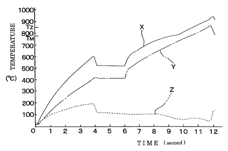
matching
transformer 19 to a resonant frequency of the high-frequency current of the
heating
inductor 4 from moment to moment by the circuit operation for making the phase
difference zero, between the high-frequency current of the heating inductor 4
and the
voltage detected by the current detector 37.
X0075)
The resonant frequency detector 38 detects the resonant frequency of the high-
frequency current of the heating inductor 4 obtained by the frequency tracking
operation,
under a standard that the phase difference becomes zero, and the detected
resonant
frequency is sent to a frequency comparator 39 of the control device 20. The
frequency
comparator 39 stores two predetermined frequencies. A first frequency is a
frequency for
an occasion when the power application of the high-frequency current to the
heating
inductor 4 should be reduced temporarily, and a second frequency is a
frequency for an
occasion when the application of the current to the heating inductor 4 should
be restart at
the original current level of the high-frequency current, in short, a
frequency for the
occasion when the application status is brought back to the original
application status
before the temporary reduction is performed. The resonant frequency of the
high-
frequency current of the heating inductor 4 sent to the frequency comparator
39 from the
resonant frequency detector 38 is compared with the first and second
frequencies.
X0076)
The resonant frequency of the high-frequency current of the heating inductor 4
CA 02500354 2005-03-24
19
corresponds to an impedance of the regions to be heated 2, and the impedance
corresponds
to the temperature of the regions to be heated 2.
X0077)
When the resonant frequency of the high-frequency current of the heating
inductor 4 is sent to the frequency comparator 39 from the resonant frequency
detector 38,
the frequency comparator 39 knows indirectly the impedance of the regions to
be heated 2
via the resonant frequency. Thus, the frequency tracker 40 and the frequency
comparator
39 and the like compose the impedance-knowing type controller 41.
X0078)
After the start of a heating work of the article 1, when a resonant frequency
of the
high-frequency current of the heating inductor 4 which is sent to the
frequency comparator
39 from the resonant frequency detector 38 coincides with the first frequency
stored in the
frequency comparator 39, the control device 20 sends the control signal to the
inverter 18,
for instructing the reduction of the power feeding from the inverse converter
22 to the
matching transformer 19, based on the order from the frequency comparator 39,
to thereby
start the step of reducing the temperature differences for reducing
temporarily the power
application of the high-frequency current to the heating inductor 4. After
that, when the
resonant frequency of the high-frequency current of the heating inductor 4
which is sent to
the frequency comparator 39 from the resonant frequency detector 38 coincides
with the
second frequency stored in the frequency comparator 39, the control device 20
sends the
control signal to the inverter 18, for instructing a restart of a power
feeding from the
inverse converter 22 to the matching transformer 19 in at original current
level, to thereby
finish the step of reducing the temperature differences.
X0079)
According to the embodiment shown in Fig. 7, changes of the impedance at the
regions to be heated 2 correspond to changes of the temperature of the whole
region of the
regions to be heated 2, therefore the step of reducing the temperature
differences can be
set up accurately in accordance with the temperature changes of the regions to
he heated 2,
as compared with the embodiment in Fig. 6 in which one sensor 27 measures one
portion
at the regions to be heated 2.
X0080)
The step of reducing the temperature differences of the embodiment in Fig. 7
as
described above is set up in a form that the power application of the high-
frequency
current to the heating inductor 4 is reduced temporarily, however, the step of
reducing the
temperature differences of the embodiment in Fig. 7 can be set up in a form
that the power
application of the high-frequency current to the heating inductor 4 is stopped
temporarily,
under a condition that a timer for restarting the power application is set up
additionally, or
CA 02500354 2005-03-24
under a condition that a resonant frequency detector for detecting a resonant
frequency
when the temperature of the regions to be heated 2 lowered to the temperature
whereat the
power application should be restarted is set up additionally.
X0081)
Fig. 8 shows another embodiment concerning an inductive portion of a heating
inductor, and Fig. 9 is a cross-sectional view taken along the line S9-S9 in
fig. 8. A
heating inductor 44 to which the high-frequency current is applied by the
power supply
device 6 is provided with a plurality of, four good conductors 44A in the
embodiment
shown in the drawing, facing respectively to the two place of the regions to
be heated 2 of
the article 1. These good conductors 44A form inductive portions generating
the
inductive eddy-current to the regions to be heated 2. The respective good
conductors
44A of which inductive portions extends in an extending direction of the
regions to be
heated 2 are arranged side by side in a width direction of the article 1,
perpendicular to the
extending direction of the regions to be heated 2 to thereby cover the
respective regions to
be heated 2 by the good conductors 44A. The four good conductors 44A provided
to
respective two regions to be heated 2 are connected in parallel with each
other.
X0082)
According to this embodiment, if an unevenness of a temperature increase
occurs
in the regions to be heated 2 which has a certain dimension in the width
direction of the
article 1, a current applied to the good conductor 44A arranged in response to
a high-
temperature portion of which electrical resistance is rather large becomes
rather small, a
current applied to the good conductor 44A arranged in response to a low-
temperature
portion of which electric resistance is rather small becomes rather large. As
a result, a heat
input to the high-temperature portion is suppressed and a heat input to the
low-temperature
portion is intensified. Accordingly, the temperature differences of the
regions to be
heated 2 are corrected to be leveled, and the unevenness of the temperature
increase at the
end of the heating work will be reduced further in conjunction with the effect
by the step
of reducing the temperature differences described above.
X0083)
Note that a power supply device of the embodiment in Fig. 8 and Fig. 9 can be
the power supply devices 16, 26, 36 shown in Fig. 5 to Fig. 7, and the power
supply
device 6 in Fig. 1 in which switching operation is performed manually can be
also
adopted.
X0084)
EFFECT OF THE INVENTION)
According to the present invention, an effect that reduction of an unevenness
of a
temperature increase at the end of a heating work can be achieved without any
specific
CA 02500354 2005-03-24
21
equipment, securing shortening of working time as an advantage of a bulk
heating.
(BRIEF DESCRIPTION OF THE DRAWINGS)
(FIGURE 1) Fig. 1 is a schematic perspective view showing a status of work
when a region to be heated of an article made of a thin sheet is heated
inductively by an
induction heating apparatus according to an embodiment of the present
invention.
(FIGURE 2) Fig. 2 is a cross-sectional view taken along the line S2-S2 in Fig.
1.
(FIGURE 3) Fig. 3 is a graph showing an experimental result when a heating
work is performed with a step of reducing a temperature difference set up
during a
temperature increase.
(FIGURE 4) Fig. 4 is a graph showing an experimental result when the heating
work is performed without the step of reducing a temperature difference during
the
temperature increase.
(FIGURE 5) Fig. 5 is a view showing an embodiment of a power supply device
of which current controller is a timer type controller.
(FIGURE 6) Fig. 6 is a view showing an embodiment of a power supply device
of which current controller is an actual temperature measurement type
controller.
(FIGURE 7) Fig. 7 is a view showing an embodiment of a power supply device
of which current controller is an impedance-knowing type controller.
(FIGURE 8) Fig. 8 is a same view as Fig. 1 showing another embodiment of an
inductive portion of a heating inductor.
(FIGURE 9) Fig. 9 is a cross-sectional view taken along the line S9-S9 in Fig.
8.
(FIGURE 10) Fig. 10 is a graph showing curves of temperature increase at
respective portions of the region to be heated thinkable theoretically when
the region to be
heated is heated inductively without the step of reducing the temperature
difference.
(FIGURE 11) Fig. 11 is a view showing an equivalent circuit of respective
portions in the region to be heated where a temperature distribution occurs.
(FIGURE 12) Fig. 12 is a view showing variations of the equivalent circuits
varying in order of (1) to (5) when the temperatures of respective portions in
the region to
be heated reach the magnetic transformation point.
(FIGURE 13) Fig. 13 is a graph showing curves of temperature increase at
respective portions of the region to be heated thinkable theoretically when
the region to be
heated is heated inductively with the step of reducing the temperature
difference set up.
(EXPLANATION OF CODES)
1 ARTICLE MADE OF THIN SHEET
2 REGION TO BE HEATED
4,44 HEATING INDUCTOR
4A INDUCTIVE PORTION
CA 02500354 2005-03-24
22
6,16,26,36 POWER SUPPLY DEVICE
24 TIMER
25 TIMER TYPE CONTROLLER
27 TEMPERATURE SENSOR
29 ACTUAL TEMPERATURE MEASUREMENT TYPE CONTROLLER
40 FREQUENCY TRACKER
41 IMPEDANCE-KNOWING TYPE CONTROLLER
44A GOOD CONDUCTOR