Note: Descriptions are shown in the official language in which they were submitted.
CA 02500565 2010-08-06
BALLOON DISSECTOR WITH CANNULA
BACKGROUND
1. Technical Field
The technical field relates to dissection devices for forming an anatomical
space within a
body, and, in particular, balloon dissection devices, balloon dissectors
having a combined
balloon tip cannula, and methods of using such apparatus.
2. Background of Related Art {
During certain surgical procedures, it is necessary to dissect tissue layers
to form an
anatomical space for accessing a surgical site, and within which surgical
instruments may be
manipulated. For example, in hernia repair surgery, it is necessary to form an
anatomical
operative cavity within the extraperitoneal space in order to dissect fascia
tissue layers from the
peritoneum and access the hernia site. Various balloon dissectors are known
for performing the
tissue dissection procedure used in hernia repair surgery. These generally
include a single device
having a dissection balloon formed on the distal end of a tube and inflation
port formed on the
proximal end of the tube. A separate cannula is used to insufflate the
extraperitoneal space.
While the currently known tissue dissection devices are useful, it would be
beneficial to
have a modular or multi-component balloon dissector device combined with a
cannula to
facilitate use in surgical procedures requiring dissection of tissue layers.
1
CA 02500565 2005-03-30
WO 2004/032756 PCT/US2003/031639
SUMMARY
There is disclosed a dissection and access assembly, for performing a surgical
procedure
including the dissection of tissue, and the provision of access to the
interior of the body. The
assembly includes a cannula assembly having a cannula housing and a dissector
assembly having
a dissector housing with attaching structure configured to engage the cannula
housing and an
elongated tube having a passage, the elongated tube extending distally from
the dissector
housing. A dissection balloon is attached to a distal end of the elongated
tube, the dissection
balloon having a chamber in communication with the passage.
The cannula assembly has a cannula defining a lumen, the cannula housing has
an orifice
communicating with the lumen and the elongated tube extends through the lumen.
The attaching
structure includes at least one movable latch movable into engagement with the
cannula housing
to affix the dissector housing to the cannula housing. The cannula housing has
a recess and the
at least one movable latch is pivotable to engage the recess. Preferably, the
at least one movable
latch is biased towards an engagement position.
The dissector housing has an inflation port in communication with the passage
for
inflating the dissection balloon. The dissector housing also has an orifice
communicating with
the passage. An obturator is received in the orifice so as to extend into the
passage and sized so
that a lumen is defined between the obturator and the tube.
The cannula housing defines an insufflation port in communication with the
lumen of the
cannula.
The dissector housing has a proximal end with an orifice that communicates
with the
passage. The orifice receives an endoscope so as to extend into the passage.
2
CA 02500565 2005-03-30
WO 2004/032756 PCT/US2003/031639
Notably, the obturator has attaching structure engageable with the dissector
housing. The
obturator includes a recess for receipt of the balloon when the balloon is in
a collapsed
configuration.
The cannula of the cannula assembly has a distal end and a balloon anchor
disposed at the
distal end. The cannula housing has a first port in communication with the
lumen of the cannula
and a second port in communication with the balloon anchor. The dissector
housing has a third
port in communication with the passage of the tube.
There is also disclosed a combined dissector and cannula assembly including a
dissector
assembly having a dissector housing, a tube and a dissector obturator and a
cannula assembly
having a cannula housing, a cannula obturator and an access cannula . The
cannula obturator is
removable from the access cannula and the tube of the dissector assembly is
received in the
access cannula so that the cannula assembly is movable along the tube of the
dissector assembly.
The cannula housing has a recess and the dissector housing includes a movable
member movable
into engagement with the recess to secure the dissector housing to the cannula
housing.
The movable member is a latch configured to engage the recess in the cannula
housing.
Preferably, the cannula obturator has a proximal cap with a movable member for
engaging a recess on the cannula housing and securing the cannula obturator to
the cannula
housing.
The dissector obturator has a member movable into engagement with a recess on
the
dissector housing to affix the dissector obturator relative to the dissector
housing. The dissector
housing includes a button engageable with the movable member to move the
movable member
relative to the dissector housing.
3
CA 02500565 2005-03-30
WO 2004/032756 PCT/US2003/031639
The dissector assembly includes a dissection balloon defining a chamber, the
dissection
balloon being attached to the tube so that the interior of the tube and the
chamber are in
communication with one another.
The access cannula has a distal end and a balloon anchor disposed at the
distal end.
There is also disclosed a method of dissecting tissue and providing an access
port by
providing a dissector and a cannula engaged with the dissector to form a
combined device. The
dissector has a tube, a dissection balloon attached to the tube so that a
chamber of the balloon
communicates with an interior of the tube and an obturator extending through
the tube, into the
chamber of the balloon. The cannula has a balloon anchor. A collar may be
mounted on the
cannula, proximal of the balloon anchor.
The combined device is inserted into an incision in a patient and tissue is
dissected with
the dissector by inflating the dissection balloon. The cannula is disengaged
from the dissector
and advanced into the incision. Thereafter the dissection balloon is deflated
and the dissector is
removed from the cannula. Preferably, the obturator is removed and an
endoscope is inserted
into the dissector so that the endoscope extends in to the chamber of the
dissection balloon.
The obturator can be removed and the endoscope inserted before dissection of
tissue.
Dissection can be performed under observation.
There is also disclosed a balloon dissector and balloon tip cannula assembly
which is
provided to facilitate forming an anatomical space within the body such as for
example an
anatomical space in the abdominal cavity for hernia repair surgeries.
The balloon dissector and balloon tip cannula assembly generally includes a
balloon tip
cannula assembly for anchoring the device to the abdominal wall and a balloon
dissector
assembly having a dissection balloon at a distal end for separating apart
layers of tissue and
4
CA 02500565 2005-03-30
WO 2004/032756 PCT/US2003/031639
forming an anatomical space. Additionally, the balloon dissector and cannula
may also include a
scope support for retention of an endo-scope which is inserted through the
balloon dissector and
used to visualize the abdominal space as the tissue layers are separated. A
tube of the scope
support also acts as to support the dissection balloon as it is inserted
through the balloon tip
cannula.
The cannula assembly generally includes a housing having a cannula extending
distally
therefrom. An anchor balloon is defined on a distal end of the cannula. A
lumen formed through
the cannula connects the inflation port with the interior of the anchor
balloon. The housing
includes an inflation port to inflate the anchor balloon and an insufflation
port to provide
insufflation fluid into the body cavity and to additionally inflate the
dissector balloon when the
balloon dissector and balloon tip cannula assembly is fully assembled. The
balloon tip cannula
assembly additionally includes a movable locking assembly having a foam pad
and lock
mechanism which is slidably mounted on the cannula. This is provided to secure
the cannula
assembly in the abdominal wall. Various sealing components are provided in the
internal
workings of the cannula such as for example a duck bill valve to prevent fluid
leakage after the
scope and dissection balloon are removed from the balloon tipped cannula
assembly and the
cavity is insufflated.
The balloon dissection assembly generally includes a tube with the dissection
balloon
affixed to a distal end of the tube. A housing is formed at the proximal end
of the tube and
includes latching structure which is engageable with the cannula housing to
retain the balloon tip
cannula assembly and the balloon dissector assembly together. The housing tube
includes a port
which, when fully assembled, aligns itself with the insufflation port on the
cannula assembly to
permit inflation of the dissection balloon.
CA 02500565 2005-03-30
WO 2004/032756 PCT/US2003/031639
The balloon dissector and balloon tip cannula assembly may additionally
includes a scope
support having an elongated scope tube which is inserted through the tube of
the balloon
dissection assembly and a scope head support for aligning the scope relative
to the scope tube.
The scope tube extends distally into the interior of the dissection balloon to
facilitate viewing of
the extraperitoneal space. When the balloon tip cannula assembly, the balloon
dissector
assembly and scope support are fully assembled, the annular space between the
inner surface of
tube and the outer surface of the scope support form an inflation lumen in
fluid communication
with the interior of the dissection balloon and the insufflation port to
inflate the dissection
balloon.
There are also disclosed methods of using the balloon dissector and balloon
tip cannula
assembly to form an anatomical space within a patient.
There are also disclosed alternate embodiments of the balloon dissector and
balloon tip
cannula assembly which generally include modular components for use with a
specific valve
assembly. A particular embodiment includes two inflation ports, one to inflate
the balloon
anchor of the balloon tip cannula assembly and a second to inflate the
dissection balloon. The
second inflation port may also be used to provide insufflation fluid into the
abdominal cavity
after the balloon dissector has been removed.
There is further disclosed an additional embodiment of a balloon dissector and
balloon tip
cannula comprised of modular components which includes three separate ports,
one for inflating
the balloon anchor of the balloon tip cannula assembly, one for providing
insufflation fluid into
the abdominal cavity, and a third port, on the balloon dissection assembly
itself, specifically
designated for inflating the dissection balloon.
6
CA 02500565 2005-03-30
WO 2004/032756 PCT/US2003/031639
BRIEF DESCRIPTION OF THE DRAWINGS
Various embodiments are described herein with reference to the drawings
wherein:
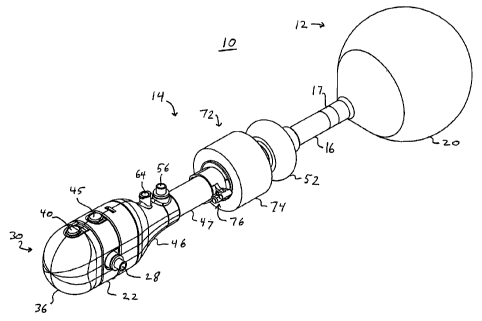
FIG. I is a perspective view of a balloon dissector and balloon tip cannula
assembly in
accordance with an embodiment of the present disclosure;
FIG. 2 is a cross-sectional view of the balloon dissector and balloon tip
cannula assembly
in accordance with the embodiment of FIG. 1;
FIG. 3 is a cross-sectional view of the balloon dissector assembly in
accordance with the
embodiment of FIGS. 1 and 2;
FIG. 4 is an exploded view of the balloon dissector assembly in accordance
with the
embodiment of FIGS. 1-3;
FIG. 5 is a cross-sectional view of the balloon tip cannula assembly in
accordance with
the embodiment of FIGS. 1-4;
FIG. 6 is an exploded view of the balloon tip cannula assembly in accordance
with the
embodiment of FIGS. 1- 5;
FIG. 7A is a perspective view of the balloon dissector and balloon tip cannula
assembly
in accordance with the embodiment of FIGS. 1-6, being used to dissect tissue;
FIG. 7B is a perspective view of the balloon dissector and balloon tip cannula
assembly
in accordance with the embodiment of FIGS. 1-6, anchoring the balloon tip
cannula assembly in
place in tissue;
FIG. 8 is a perspective view of a balloon dissector and balloon tip cannula
assembly in
accordance with a further embodiment of the present disclosure;
FIG. 9 is an exploded view of the balloon dissector and balloon tip cannula
assembly in
accordance with the embodiment of FIG. 8;
7
CA 02500565 2005-03-30
WO 2004/032756 PCT/US2003/031639
FIG. 10 is a cross-section of the distal end of the balloon dissector assembly
along line
10-10 of FIG. 8;
FIG. 11 is an end view, of the deflated balloon and balloon cover in
accordance with the
embodiment of FIGS. 8-10;
FIG. 12 is a cross-sectional view of the proximal end of the balloon dissector
and balloon
tip cannula assembly in accordance with the embodiment of FIGS. 8-11;
FIG. 13 is a perspective view of the balloon tip cannula assembly in
accordance with the
embodiment of FIGS. 8-12, with the balloon anchor being inflated;
FIG. 14 is a perspective view of the balloon dissector and balloon tip cannula
assembly in
accordance with the embodiment of FIGS. 8-13, with the dissection balloon
being inflated;
FIG. 15 is a side elevation view of the inflated balloon dissector in
accordance with the
embodiment of FIGS. 8-14;
FIG. 16 is a perspective view of a scope and scope support tube being removed
from the
combined balloon dissector and balloon tip cannula assembly in accordance with
the
embodiment of FIGS. 8-15;
FIG. 17 is a perspective view of a balloon dissector partially removed from
the balloon
tip cannula assembly in accordance with the embodiment of FIGS. 8-16;
FIG. 18 is a top view of a balloon dissector and balloon tip cannula assembly
in
accordance with another embodiment of the present disclosure;
FIG. 19 is a cross-sectional view taken along line 19-19 of FIG. 18
illustrating a collar
lock mechanism;
FIG. 20 is an exploded perspective view of the balloon dissector and balloon
tip cannula
assembly in accordance with the embodiment of FIGS. 18 and 19;
8
CA 02500565 2005-03-30
WO 2004/032756 PCT/US2003/031639
FIG. 21 is an exploded perspective view of the balloon tip cannula assembly in
accordance with the embodiment of FIGS. 18-20;
FIG. 22 is an exploded perspective view of the balloon dissector assembly in
accordance
with the embodiment of FIGS. 18-21;
FIG. 23 is a sectional view taken along the line 23-23 of FIG. 18;
FIG. 23A is an enlarged area of detail of the balloon anchor of FIG. 23;
FIG. 23B is an enlarged area of detail of the proximal inflation port of FIG.
23;
FIG. 24 is a top view of the balloon dissector and balloon tip cannula
assembly in
accordance with a further embodiment of the present disclosure; and
FIG. 25 is a sectional view taken along line 25-25 of FIG. 24.
DETAILED DESCRIPTION OF PREFERRED EMBODIMENTS
A dissection and access assembly comprising a balloon dissector and cannula
assembly
in accordance with an embodiment of the invention is shown in FIGS. 1-7B.
Referring to
FIGS. 1 and 2, balloon dissector and cannula assembly 10 has a balloon
dissector assembly 12
and a balloon tip cannula assembly 14. Balloon dissector assembly 12 has an
elongated tube 16
having a distal end 17 and a proximal end 18 and defining a passage 19. A
dissection balloon 20
is affixed to the distal end 17 of tube 16. Dissection balloon 20 forms a
chamber 21 that
communicates with passage 19. Dissection balloon 20 is round in shape and
formed from an
elastic material so as to expand to a shape that follows the path of least
resistance in tissue.
FIGS. 3 and 4 show balloon dissector assembly 12 separately from balloon tip
cannula
assembly 14. A dissector housing 22 is formed on the proximal end 18 of
elongated tube 16.
Dissector housing 22 has an orifice 24, at a proximal end 23 thereof, and
includes a seal 26.
9
CA 02500565 2005-03-30
WO 2004/032756 PCT/US2003/031639
Dissector housing 22 may be formed of two parts to support seal 26. Dissector
housing 22
defines an inflation port 28 (FIG. 1) dimensioned for receiving a one-way
inflation valve. The
inflation valve and inflation port 28 communicate with dissection balloon 20
through elongated
tube 16.
A dissector obturator 30 having an elongate shaft 32 and a distal tip 34 is
positionable
through orifice 24 in dissector housing 22, through passage 19 in tube 16, and
into chamber 21 of
dissection balloon 20. The outer surface of obturator shaft 32 and the inner
surface of elongated
tube 16 form an inflation lumen between inflation port 28 and dissection
balloon 20. A
proximal end 35 of dissector obturator 30 has a cap 36 which carries resilient
latches 38
connected to buttons 40. When dissector obturator 30 is received in dissector
housing 22 and
advanced into tube 16, distal tip 34 engages dissection balloon 20 and
supports it in an elongated
shape. Dissector obturator 30 is sized so that obturator shaft 32 stretches
dissection balloon 20,
supporting dissection balloon 20 in a collapsed configuration. Latches 38
engage recesses 42 on
proximal end 23 dissector housing 22. Additional latches 44, connected to
buttons 45, are
provided on dissector housing 22 for interconnecting dissector housing 22 to a
cannula housing
46 of balloon tip cannula assembly 14.
In order to inflate dissection balloon 20, a source of inflation pressure is
releasably
attached to inflation port 28 and pressurized fluid is introduced through
inflation port 28 and
communicated through elongated tube 16 to dissection balloon 20.
Referring to FIGS. 5 and 6, which show balloon tip cannula assemblyl4
separately from
balloon dissector assembly 12, balloon tip cannula assembly 14 has a cannula
47 which is open
at its proximal and distal ends 48, 49 to define an access lumen 50 for
receipt of surgical
CA 02500565 2010-08-06
instruments therethrough. An inflatable balloon anchor 52, having a generally
toroidal shape, is
disposed adjacent distal end 49 of cannula 47.
Cannula housing 46 is attached to cannula 47 at proximal end 48 of cannula 47.
Cannula
housing 46 has an orifice 54 that communicates with the access lumen 50. A
valve port 56 is
provided in a surface of cannula housing 46. Valve port- 56 is dimensioned to
receive a check
valve in a substantially fluid-tight sealing manner. An inflation lumen 58 is
defined between the
inner surface and the outer surface of the cannula 47 and extends to a distal
port 60 open to
balloon anchor 52. Valve port 56 communicates with a proximal port 62 at a
proximal end of
lumen 58, so that valve port 56 communicates with balloon anchor 52 via lumen
58.
In order to inflate balloon anchor 52, a source of inflation pressure is
releasably attached
to valve port 56, introducing pressurized fluid through valve port 56 to
balloon anchor 52,
causing balloon anchor 52 to expand.
An insufflation port 64 is also provided on cannula housing 46, and in fluid
communication with the interior of cannula housing 46 and cannula 47, to
provide insufflation
fluid to the interior of a patient's body through access lumen 50 of cannula
47. An insufflation
port 64 is disposed distally of a seal assembly 66 provided in cannula housing
46. Seal assembly
66 seals the interior of the cannula 47 during insufflation, so as to maintain
insufflation pressure
within the body. Seal assembly 66 generally includes an instrument seal 68 for
sealing around
instruments inserted into cannula 47 and a seal 70 for sealing cannula 47 in
the absence of any
instruments inserted into cannula 47. Instrument seal 68 may comprise any
known instrument
seal used in cannulas and/or trocar devices, such as a septum seal. Seal 70
may comprise any
known seal for closing off the passageway with access lumen 50, such as a
duckbill seal or
flapper valve.
11
CA 02500565 2005-03-30
WO 2004/032756 PCT/US2003/031639
A skin seal 72 is slidably mounted on the outside surface of cannula 47. Skin
seal 72
includes a compressable foam collar 74 mounted on a clamp 76 for securing skin
seal 72 in a
desired longitudinal position along the cannula 47. Skin seal 72 may be
constructed as described
in more detail hereinbelow with regard to skin seal assembly 260, as shown in
FIG. 19.
Referring to FIGS. 5 and 6, balloon tip cannula assembly 14 includes a cannula
obturator
78 having a proximal cap 80 and a distal end 82. Obturator 78 is inserted in
the orifice 54 of
cannula housing 46, and advanced through access lumen 50 of cannula 47, so
that a distal end 82
of cannula obturator 78 extends out of distal end 49 of cannula 47. Cannula
housing 46 has a
proximal end 83 with recesses 84 for receiving latches 86 carried by proximal
cap 80 of cannula
obturator 78. Buttons 88 are also attached to latches 86 for disengaging
latches 86 from recesses
84. Latches 44 on dissector housing 22 also engage recesses 84 in cannula
housing 46, when
balloon dissector assembly 12 is assembled to balloon tip cannula assembly 14.
FIGS. 1 and 2 show balloon dissection assembly 12 and balloon tip cannula
assembly 14
assembled together. To assemble balloon dissector assembly 12 and balloon tip
cannula
assembly 14, the cannula obturator 78 is removed from cannula 47. Balloon
dissector assembly
12 is inserted into orifice 54 of cannula housing 46 and advanced through
acess lumen 50 of
cannula 47 so that latches 44 on dissector housing 22 are engaged with
recesses 84 in cannula
housing 46, inter-connecting the assemblies. (FIG. 2).
Balloon dissector assembly 12 is used for dissecting tissue along natural
tissue planes in
general, laparoscopic, vascular endoscopic, plastic or reconstructive surgery
or other procedures
requiring the separation of tissue. A suitably sized incision is made in the
patient's skin. Next,
assembled balloon dissector and cannula assembly 10 is inserted into the
incision, using the
dissector obturator 30 to tunnel a passage beyond the point of incision.
12
CA 02500565 2005-03-30
WO 2004/032756 PCT/US2003/031639
Inflation pressure is supplied through inflation port 28 from a suitable
outside source and
is communicated to dissection balloon 20. As pressure is applied, dissection
balloon 20 expands.
The expansion of dissection balloon dissects surrounding tissue along natural
tissue planes.
Once the desired space is created, dissection balloon 20 is deflated by
removal of dissector
obturator 30 which allows the inflation pressure to be relieved through the
orifice 24 in dissector
housing 22.
In an alternative, obturator 30 is removed from tube 16 and replaced with an
endoscope.
Then, balloon dissector and cannula assembly 10 is inserted into the skin
incision and the
dissector balloon 20 is inflated as discussed above. The scope is used for
supporting balloon 20,
as well as, viewing the dissected space and for viewing during dissection.
After dissection balloon 20 is deflated, dissector housing 22 is un-latched
from cannula
housing 46 by pressing buttons 45 on dissector housing 22. Cannula 47 is
advanced along
balloon dissector tube 16 and positioned within the incision so that the
balloon anchor 52 is
located inside the body cavity. Inflation fluid is supplied through valve port
56 thereby
communicating the inflation fluid to balloon anchor 52 at distal end 47of
cannula 47, expanding
balloon anchor 52. After anchor balloon 52 is expanded, it is brought into
engagement with the
underside of the patient's abdominal wall.
Skin seal 72 is moved into position against the surface of the patient
abdominal wall and
secured. Foam collar 74 of skin seal 72 forms a pressure barrier, thereby
minimizing the loss of
insufflation pressure through the opening in the patient's abdominal wall and,
in combination
with anchor balloon 52, secures balloon tip cannula assembly 14 to the
patient's body.
The balloon dissector assembly 12 is removed from the cannula 47 and surgical
instruments are introduced to the surgical site through the orifice 54 in
cannula housing 46 and
13
CA 02500565 2005-03-30
WO 2004/032756 PCT/US2003/031639
access lumen 50 in cannula 47. Examples of such surgical instruments include,
but are not
limited to, endoscopes, surgical suturing devices, and surgical device
applicators.
Upon completion of the surgical procedure, the surgeon deflates anchor balloon
52 by
releasing the check valve attached to valve port 56. Once anchor balloon 52 is
sufficiently
deflated, cannula 47 is removed from the incision.
Different versions of the balloon dissector and balloon tip carmula assembly
10 may be
provided with different types of dissection balloons for each version.
Desirably, one version
includes a round balloon of an elastic material and another version includes a
laterally extending
oval balloon that is desirably inelastic. The balloons may be elastic,
inelastic or a combination of
materials having both characteristics. The selection of balloon is left up to
the surgeon.
In further embodiments, a laterally extending oval dissection balloon, like
that shown in
FIG. 14, is provided on the balloon dissector assembly 12. The balloon is
attached to tube 16 so
that obturator 30 extends into the balloon. In a collapsed configuration, the
lateral margins of the
dissection balloon are rolled inwardly toward dissector obturator 30 of
balloon dissector
assembly 12. Two recessed flats 90 are defined in each of the lateral sides of
obturator 30, for
accommodating the rolled margins of the dissection balloon. A sleeve is
provided around
dissection balloon to retain the dissection balloon in a collapsed condition
(like the sleeve shown
in FIG. 11) during insertion into the body and prior to inflation. Preferably,
the sleeve comprises
a sheet of polymeric material that is attached to the material of the
dissection balloon. The
sleeve includes a longitudinal weakened perforated region such that, upon
inflation of the
dissection balloon, the sleeve separates along the perforations and releases
the dissection balloon.
As the dissection balloon is inflated, the dissection balloon unrolls or
unfolds in a lateral
direction with respect to the tube 16.
14
CA 02500565 2005-03-30
WO 2004/032756 PCT/US2003/031639
Referring to FIGS. 7A and 7B, the use of balloon dissection and balloon tip
cannula
assembly 10 in a hernia repair will now be generally described. Incise tissue
in or around the
umbilicus and dissect down to the posterior Rectus sheath using common
dissection tools. Once
the posterior Rectus sheath has been located, insert the distal tip of the
combined balloon
dissector and cannula assembly 10 through incision I into the extraperitoneal
space on an oblique
angle and toward the pubic bone. Blunt dissect by pushing on the balloon
dissector and balloon
tip cannula assembly 10 until the distal tip is in the proper position. As
discussed above, certain
preferred embodiments have a dissection balloon 20 provided with a balloon
cover having
perforations such that upon forcing air or liquid into dissection balloon 20 ,
the perforations
break and the balloon is allowed to expand to its full size in order to
separate tissue layers,
thereby forming an anatomical space. Once dissection balloon 20 has been
properly positioned,
force air or liquid through the inflation port 28 in order to inflate
dissection balloon 20.
(FIG.7A). Desirably, buttons 40 are pressed to disconnect the obturator 30
from balloon
dissector assembly 12 and a scope is desirably positioned in tube 16 of
balloon dissector
assembly 12. The scope can be used in order to visualize the extraperitoneal
space and anatomy
during inflation of dissection balloon 20 as the space is being created. After
the desired space is
created, the dissection balloon 20 is deflated by removing the scope from tube
16. In the absence
of a scope, dissector obturator 30 should be in place to support deflated
dissection balloon 20.
As noted above, removal of dissector obturator 30 will allow dissection
balloon 20 to deflate.
With the deflated dissection balloon 20 left in the extraperitoneal space,
buttons 45 are pressed to
disconnect the balloon dissector assembly 12 from balloon tip cannula assembly
14 and balloon
tip cannula assembly 14 is slid forward into the incision I so that balloon
anchor 52 is positioned
in the extraperitoneal compartment. Balloon anchor 52 is inflated through
valve port 56 to
CA 02500565 2010-08-06
engage the inner surface of the extraperitoneal compartment. Subsequently,
skin seal 72 is
moved distally such that the foam collar 74 engages on the outer surface of
the incision site and
the collar is locked in place on cannula 47 to retain balloon tip cannula
assembly 14. (FIG. 7B).
Thereafter, deflated balloon dissector assembly 12 can be removed from balloon
tip cannula
assemblyl 4. Insufflation of the anatomical space can be provided through the
insuffl-ation port
64 in balloon tip cannula assembly 12. A scope may now be positioned in
balloon tip cannula
assembly 14 to view the hernia site. Thereafter, working ports are placed into
the created space
so that known instruments may be utilized to perform the hernia repair
surgery. Upon
completion of the repair, balloon tip cannula assembly 14 is removed by
deflating balloon
anchor 52, preferably releasing skin seal 72 and withdrawing balloon tip
cannula assembly 14
from the body cavity.
A dissection and access assembly comprising a balloon dissector and balloon
tip cannula
assembly in accordance with a further embodiment is shown in FIGS. 8-17.
Referring to FIG. 8,
a balloon dissector and balloon tip cannula assembly 110 generally includes a
balloon dissector
assembly 114 mounted in a balloon tip cannula assembly 112. Balloon dissector
assembly 114
includes a dissection balloon 116 attached to a tube 118. Balloon dissection
assembly 114
extends through balloon tip cannula assembly 112.
Balloon tip cannula assembly 112 has a proximal end 142, a distal end 144 and
a bore
140, and includes a cannula housing 120 having a cannula 122 extending
distally therefrom. The
cannula 122 defines an access lumen 150. Preferably, a skin seal 124 is
movably mounted along
cannula 122 and includes a lock mechanism 126 to secure skin seal 124 at a
desired location
along cannula 122. Balloon tip cannula assembly 112 also includes a balloon
anchor 128
mounted to cannula 122 and secured thereon by locking rings 130. Preferably,
balloon anchor
16
CA 02500565 2010-08-06
128 is formed of a generally non-latex balloon type material, whereas, skin
seal 124 is preferably
formed of a flexible or soft foam material.
Cannula housing 120 includes an anchor port 132 which is in fluid
communication with
the interior of balloon anchor 128. Cannula housing 120 further includes a
port 134 which is
provided to provide insufflation in the body cavity and inflation to the
dissection balloon 116 in a
manner described in more detail herein below.
A scope support 136 extends through balloon dissector assembly 114 to a
position within
dissection balloon 116. While it may not specifically supplied as part of the
assembled balloon
dissector and balloon tip cannula assembly 110, there is illustrated a scope
138 inserted through
and supported by scope support 136. Scope 138 is configured to be attached to
an external
viewing mechanism, such as, for example, an external camera system. This
allows viewing
through the interior of dissection balloon 116 as dissection balloon 116 is
manipulated within the
body cavity.
Referring now to FIG. 9, there is disclosed balloon dissector and balloon tip
cannula
assembly 110 illustrated with essential parts separated including balloon tip
cannula assembly
112, balloon dissector assemblyl 14, scope support 136 and scope assembly 138.
Balloon dissector assembly 114 is configured to be inserted through balloon
tip cannula
assembly 112 and generally includes a tube 118 having an attachment plate 148
at a proximal
end 151 of tube 118. Dissection balloon 116 is attached to and extends
distally from a distal end
152 of tube 118. Tube 118 includes a bore 154 extending therethrough and
aligned with a plate
opening 156 in plate 148. Bore 154 extends from plate opening 156 to distal
end 152 of tube
118. This allows the insertion of scope support 136 and scope assembly 138
through tube 118 and into
dissection balloon 116.
17
CA 02500565 2010-08-06
In order to inflate dissection balloon 116, tube 118 is provided with a port
158 which,
when tube 118 is positioned within balloon tip cannula assembly 112, is
aligned with port 134.
Thus, port 134 is used for insufflation of fluid into the body cavity, when
balloon dissector and
balloon tip cannula assembly 110 are disassembled, and also used for inflating
dissection balloon
116 when assembled. Attachment plate 148 is provided with latch structure 160
in order to
engage balloon tip cannula assembly 112 and retain balloon dissector assembly
114 in
engagement with balloon tip cannula assembly 112.
Scope support 136 generally includes an elongated scope tube 162 having a
scope head
support 164 mounted on a scope tube proximal end 166. Scope tube 162 defines a
bore 168
extending from the proximal end 166 to a distal end 170 for receipt of scope
assembly
138 therethrough. Scope head 164 includes a generally U-shaped body portion
172
having a pair of up right supports 174 which are configured to support and
align scope
assembly 138 within scope support 136.
As noted hereinabove, scope assembly 138 is not an item generally included
with assembled balloon dissector and cannula assembly 110 but is discussed
herein for
the purposes of illustration of use. Specifically, scope assembly 138
generally includes
a scope body 176 having an elongate scope 178 extending distally therefrom.
Scope
body 176 is provided with a camera adaptor 180 at a proximal end and may
generally
include a light guide 182 for illuminating through scope assembly 138. As is
common,
a lens, 184 is provided at a distal end 186 of scope assembly 138. Scope body
176 may
be affixed to proximal end 188 of scope 178 in known matter or may be
integrally
formed therewith.
With the exception of scope assembly 138, balloon dissector and cannula
assembly 110 is provided in an assembled condition with dissection balloon 116
deflated and inserted through cannula bore 140 to a position where inflation
port 134 is
in direct alignment with port 158 of tube 118. 18
CA 02500565 2005-03-30
WO 2004/032756 PCT/US2003/031639
Latch structure 160 engages cannula housing 120 to secure balloon tip cannula
assembly 112
with balloon dissector assembly 114.
Scope support 136 is positioned such that scope tube 162 extends through plate
opening
156 and bore 154 of tube 118. Scope 178 supports dissection balloon 116.
In order to positively lock balloon dissector assembly 114 to balloon tip
cannula
assembly 112, latch structure 160, provided on attachment plate 148, generally
includes a pair of
apposed latch arms 190 which are pivotably mounted to rods 192 positioned on
attachment plate
148. Latch arms 190 include proximal levers 194 and distal hooks 196.
Preferably, distal hooks
196 are biased radially inwardly such that upon squeezing, proximal levers 194
move distal
hooks 196 radially outwardly. A flange 198 is formed on a proximal end 142 of
cannula housing
120. By advancing balloon dissector assembly 114 within balloon tip cannula
assembly 112,
distal hooks 196 engage flange 198 and pivot outwardly, latching into
engagement with flange
198.
As noted hereinabove, skin seal 124 and lock mechanism 126 are slidably
mounted on
cannula 122. Skin seal 124 and lock mechanism 126 are connected by a backing
plate 200
formed on lock mechanism 126 onto which skin seal 124 is affixed. Lock
mechanism 126 is of
the type that reduces in diameter and engages cannula 122. Preferably lock
mechanism 126 is a
clamp or a cam-over center type clamp. However, other locking mechanisms may
be used to
secure the position of skin seal 124 on cannula 122.
Referring now to FIG. 10, a proximal end of dissection balloon 116 is bonded
to distal
end 152 of tube 118. An annular space 204 between an inner surface of tube 118
and an outer
surface of scope tube 162 provides an annular inflation lumen for inflating
and deflating
dissection balloon 116.
19
CA 02500565 2005-03-30
WO 2004/032756 PCT/US2003/031639
As best shown in FIG. 11, in a collapsed condition, dissection balloon 116 is
rolled up on
and surrounded by a balloon cover 206 which includes a longitudinal
perforation 208. Upon
inflation of dissection balloon 116 through annular space 204, perforations
208 are forced apart
to release dissection balloon 116 from cover 206.
Referring now to FIG. 12, the internal structure of balloon tip cannula
assembly 112 will
now be described. Balloon tip cannula assembly 112 has a cannula 122 which
includes an
anchor inflation lumen 210 in fluid communication with balloon anchor 128. At
its proximal
end, lumen 210 communicates with a proximal port 212 open to anchor port 132.
Lumen 210
communicates with a distal port in the cannula 122. The balloon anchor 128 is
mounted over the
distal port. Thus, inflation pressure through anchor port 132 extends into
port 112, and down
inflation lumen 210 to radially expand and inflate balloon anchor 128.
Cannula housing 120 is provided with a duck bill seal 214 which seals cannula
housing
120 in the absence of balloon dissector assembly 114, or any other instrument
inserted in balloon
tip cannula assembly 112. Thus, balloon tip cannula assembly 112 can be used
to insufflate a
body cavity by forcing inflation fluid through port 134 and into cannula bore
140. A mounting
bracket 216 is provided within cannula housing 120 to secure duck bill seal
214. Additionally,
an annular septum seal 218 is provided to seal cannula housing 120 at the
proximal end of the
assembly thereby preventing any dissection balloon inflation fluid from
exiting proximally along
the outer surface of the scope tube 162.
In a first method in accordance with an embodiment of the invention, a sharp
tip trocar is
positioned within bore 140 of balloon tip cannula assembly 112 and used to
puncture the
abdominal wall of the body such that balloon anchor 128 is located internal to
the body.
Thereafter, the sharp trocar is removed from cannula bore 140. A syringe, such
as for example
CA 02500565 2010-08-06
syringe 220, shown in FIG. 13, has a tubular body portion 222, plunger 228 and
a proximal
flange 224 and a distal inflation nozzle 226. Syringe 220 is provided for
introducing inflation
fluid into balloon anchor 128. Preferably, the inflation fluid is of a body
compatible type such as
for example, saline solution. Distal inflation nozzle 226 is inserted in port
132 and plunger 228
is depressed to force saline fluid from tubular body 222 through port 132,
port 212 and into
lumen 210. Forcing fluid through lumen 210 forces the fluid into balloon
anchor 128 to expand
balloon anchor 128 inside of the abdominal wall. Thereafter, locking mechanism
126 is
loosened to advance skin seal 124 distally to compress skin seal 124 against
the outer surface of
the abdominal wall. Lock mechanism 126 is then tightened to maintain the seal.
Thereafter,
balloon dissector assembly 114 fully assembled with scope support 136 and
scope
assembly 138 may be inserted through cannula bore 140 to position dissection
balloon
116 within the anatomical space.
Referring now to FIGS. 12 and 14, a similar syringe 220 provided with saline
can be
inserted in port 134 and plunger 228 depressed to force the inflation fluid
through port 158 in
tube 118 and into the annular space 204 defined by an inner surface of tube
118 and an outer
surface of scope tube 162 to thereby inflate dissection balloon 116. As noted
above, dissection
balloon 116 is covered with a balloon cover 206 having longitudinal
perforations 208 extending
therealong. As fluid is forced into dissection balloon 116 it expands, tearing
perforations 208,
and releasing dissection balloon 1] 6 from balloon cover 206.
The shape of dissection balloon 116 can vary upon the area of use in the
anatomical
structure and may include a longitudinally oval shape or other shapes such as
kidney shaped,
laterally extending, round, etc., depending on the need of the surgeon. Once
dissection balloon
116 has been used to create an anatomical space separating tissue layers so
that procedures can
21
CA 02500565 2010-08-06
be performed in the anatomical space, dissection balloon 116 can be deflated
by withdrawing
fluid through port 134 to deflate dissection balloon 116. Subsequently, a
second syringe or bulb
could be inserted into port 132 to deflate balloon anchor 128 and the entire
balloon dissector
assembly 114 removed from balloon tip cannula assembly 112.
Alternatively, dissection balloon 116 can be deflated by withdrawing scope
tube 162
from bore 154 of tube 118 to deflate dissection balloon 116. The collapsed
dissection balloon
116 and tube 118 can be withdrawn from balloon tip cannula assembly 112
leaving balloon tip
cannula assembly 112 in place for receipt of other instruments.
A dissection and access assembly comprising a balloon dissector and balloon
tip cannula
assembly in accordance with a further embodiment is shown in FIGS. 18-23.
Referring now to
'FIG. 18, balloon dissector and cannula assembly 250 is provided in a modular
form so that the
various components or sub-assemblies may be disassembled to facilitate
cleaning and allow for
interchangeability of parts with various sizes and shape components. Balloon
dissector and
cannula assembly 250 generally includes a balloon tip cannula assembly 252
having a removable
insufflation valve assembly 254. A balloon. dissector assembly 256 extends
through balloon tip
cannula assembly 252 and is configured to receive a scope tube assembly 258
therethrough in the
matter similar to that described above with respect to balloon dissector and
cannula assembly
110. A skin seal assembly 260 is movably mounted on balloon tip cannula
assembly 252.
Referring for the moment to FIG. 19, the components of skin seal 260 will now
be
described. As noted above, skin seal 260 is provided to insure a secure fit
against the outer
surface of the abdominal cavity. Skin seal 260 generally includes a base 262
and a foam collar
264 affixed to base 262. A lock mechanism including a split clamp 266 is
positioned on base
262 and includes pins 268 and 270 at the split ends. The locking action of
skin seal 260 is what
22
CA 02500565 2010-08-06
is commonly known as an over-center type clamp or lock. Thus, skin seal 260
includes a cam
lever 272 and a connector 274 which is pivotally connected to cam lever 272 by
a pin 276. An
opposed end of connector 274 is pivotally connected to pins 270 and 268. Thus,
movement of
cam lever 272 cams or moves pins 268 or 270 closer together thereby
contracting split clamp 266
to engage the outer surface of a cannula of balloon tip cannula assembly 252.
Referring now to FIG. 20, the major sub-assemblies or components of balloon
dissector
and cannula assembly 250 are illustrated. Balloon tip cannula assembly 252
generally includes a
cannula 278 having a balloon anchor 280 located at a distal end 282 of cannula
278. A pair of
locking rings 284,286 secures balloon anchor 280 to cannula 278. An adaptor
288 is
position on the proximal end 290 of cannula 278 and is provided with a port
292 which
is in fluid communication with the interior of balloon anchor 280. Unlike the
prior
embodiment, balloon tip cannula assembly 252 does not include an insufflations
port.
This is provided in a separate component. Balloon tip cannula assembly 252
defines a
throughbore 294 for receipt of the various sub-components similar to that
described
above with respect to balloon dissector and cannula assembly 110.
To provide a port for insufflation of the body cavity and for inflating the
interior of a
dissecting balloon, balloon dissector and cannula assembly 250 includes a
valve assembly 296
connected at its distal end 298 to a proximal end 300 of adaptor 288.
Preferably, this connection
is by a bayonet type fitting, but may comprise a threaded or latching
connection.
Valve assembly 296 includes a port 302 which, when connected to balloon tip
cannula
assembly 252, is in fluid communication with bore 294. This allows balloon tip
cannula
assembly 252 and valve assembly 296 to be used as a conventional cannula to
provide
insufflation fluid in a body cavity. Valve assembly 296 is provided with a
duck bill valve 304
23
CA 02500565 2005-03-30
WO 2004/032756 PCT/US2003/031639
located proximally of port 302. Valve assembly 296 has a bayonet type fitting
at a proximal end
306. This proximal end 306 is provided to engage various alternative
components.
Balloon dissector assembly 256 generally includes an elongated dissector tube
308
having a dissection balloon 310 affixed to a distal end 312 of dissector tube
308. Ports 314 are
provided in tube 308 to receive inflation fluid to inflate dissection balloon
310. An end cap 316
having a bayonet style fitting is formed on tube 308. Tube 308 defines a
throughbore 318 for
receipt of scope tube assembly 258 in a manner similar to that described
herein above. As noted,
end cap 316 has a bayonet style fitting which is configured to engage the
bayonet style fitting at
proximal end 306 of valve assembly 296 to secure tube 308 to valve assembly
296. When
dissection balloon assembly 256 is connected to valve assembly 296 ports 314
are located
distally of duck bill valve 304 or in a position to receive inflation fluid
through port 302 to inflate
dissection balloon 310.
Scope tube assembly 258 has a scope tube 322 having a support head 324 formed
on a
proximal end of tube 322. Scope tube 322 defines a throughbore 328 for receipt
of a scope (not
shown).
It should be noted that, prior to assembling balloon dissector assembly 256
with valve
assembly 296, scope tube assembly 258 should be inserted through bore 318 in
balloon tube 308.
This is necessary to insure that scope tube 322 provides support for
dissection balloon 310 as the
combined balloon assembly 256 and scope tube assembly 258 are inserted through
valve
assembly 296 and balloon tip cannula assembly 252.
When balloon tip cannula assembly 252 and valve assembly 296 are used without
balloon
dissector assembly 256 and scope tube assembly 258 there is provided a valve
end cap 330
having a bayonet fitting at its distal end 332 which is configured to engage
the corresponding
24
CA 02500565 2010-08-06
bayonet fitting at proximal end 306 of valve assembly 296. End cap 330 is
provided with a
throughbore 334 which may include various styles of seal assemblies to receive
various
operative instruments therethrough.
Referring now to FIG. 21, as noted above, balloon tip cannula assembly 252
includes a
balloon anchor 280 affixed to a distal end 282 of cannula 278 by lock rings
284 and 286.
Adaptor 288 includes an adaptor body 336 and a coupler 338. The distal end 340
of
coupler 338 is configured to lockingly engage proximal end 342 of adaptor body
336. A check
valve 344 is mounted within port 346 on valve body 336.
Cnnnula 278 is provided with a distal port 348 and a proximal port 350. Ports
348 and
350 are in fluid communication with one another. Distal port 348 is open to
the interior of
balloon anchor 280 while proximal port 350, when cannula 278 is coupled to
adaptor body 336,
is in alignment with inflation port 346. In order to assemble cannula 278 to
adaptor body 336, an
O-ring 352 is initially positioned within adaptor body distal end 354 and
retaining ring 356
positioned over O-ring 352. Thereafter cannula 278 maybe assembled to adaptor
body 336 by a
threaded connection or other known means. Prior to attaching coupler 338 to
adaptor body 336 a
O-ring 358 is positioned within proximal end 342 of 336 and coupler 338 is
than connected to
adaptor body 336.
A retainer 360 is positioned within a proximal end 362 of coupler 338 and a
spacer 364
and retaining ring 366 are positioned over retainer 360. Finally an O-ring 370
is positioned
within proximal end 362 of coupler 338 to complete the assembly of balloon tip
cannula
assembly 252.
While not specifically shown, a skin seal such as, for example, skin seal 260
(FIG. 19)
maybe provided on cannula 278 prior to attachment of cannula 278 with adaptor
body 336.
CA 02500565 2005-03-30
WO 2004/032756 PCT/US2003/031639
Referring to FIG. 22, there is illustrated balloon dissector assembly 256 with
parts
separated. As noted above, while not shown, a balloon is mounted to distal end
312 of tube 308.
Tube 308 is provided with a port 314 for inflating the dissection balloon. End
cap 316 of balloon
dissector assembly 256 generally includes a cap 372 having an O-ring 374
positioned within a
seat 376 of cap 372. A coupler 380 is positioned over O-ring 374 and secured
there by a retainer
ring 378. A coupler 380 is configured to engage seat 376, end caps 372 and is
secured therein by
means of a retaining ring 382. An alignment tab 384 is formed on a proximal
end 386 of tube
308 and is configured to engage corresponding structure 388 within adaptor
bore 390.
Referring now to FIG. 23, it can be seen that an inflation lumen 392 extends
between
distal port 348 in cannula 278 and proximal port 350 in cannula 278. As shown,
proximal port
350 is in fluid communication with check valve 344 and port 292 to facilitate
inflating the
balloon anchor 280.
Similarly, proximal ports 314 in tube 308 are in fluid communication with port
302 in
valve assembly 296. Thus, the inner surface of tube 308 and an outer surface
of scope tube 322
form an inflation lumen for the dissection balloon.
A dissection and access assembly comprising a balloon dissector and cannula
assembly
400 in accordance with a further embodiment is shown in FIGS. 24 and 25.
Balloon dissector
and cannula assembly 400 is similar to the above described embodiments and
includes a balloon
dissector assembly 401 and a balloon tip cannula assembly 402. However,
balloon dissector
assembly 401 includes separate insufflation and dissection balloon inflation
ports. Balloon tip
cannula assembly 402 has a cannula 406 having an balloon anchor 404 affixed to
cannula 406 at
a distal end 408. Cannula 406 is provided with an adaptor 410 having a port
412. Distal and
26
CA 02500565 2005-03-30
WO 2004/032756 PCT/US2003/031639
proximal ports 414 and 416 extend through tube 406. A lumen 418 is defined in
cannula 406,
extending between distal port 414 and proximal port 416, for inflating balloon
anchor 404.
Balloon dissector assembly 401 includes a valve body 420 having an
insufflation port
422 and a duck bill valve 424 disposed therein.
Balloon dissector assembly 401 also includes a tube 426 having a distal end
428 to which
a dissection balloon similar to those described hereinabove is bonded (not
shown). A dissector
housing 430 is provided on the proximal end 432 of tube 426 and includes an
inflation port 434.
An inflation lumen 436 for inflating the dissection balloon is formed between
inner surface of
balloon tube 426 and outer surface of a scope tube 438 of a scope support 440
in a manner
similar to that described with regard to previous embodiments.
The balloon dissector and cannula assembly can be made from any medical grade
material, including metals and plastics. The apparatus is made using well-
known techniques.
It will be understood that various modifications may be made to the
embodiments
disclosed herein. For example, other configurations of securing a cannual
assembly to a balloon
dissector assembly may be provided to form a combined and engaged device.
Additionally,
other balloon shapes and construction such as, for example elastic, in
elastic, oval, kidney
shaped, along with constructions providing differential expansion
characteristics may be
provided. Further, the terminology of similar components with the various
embodiments should
not be construed as specific to any particular embodiment.
The shape and material of the dissection balloon may be selected as desired
for the
particular surgical procedure. For example, the balloon may have the round
shape of a globe, a
flattened round shape, may be elongated in a lateral direction with respect to
the longitudinal axis
of the device, or may have any other shape. The material of the balloon may be
elastic, so as to
27
CA 02500565 2005-03-30
WO 2004/032756 PCT/US2003/031639
follow a path of least resistance in the body, inelastic so as to assume a
predetermined shape
upon inflation, or a combination of elastic and inelastic materials. The
balloon dissector and
cannula assembly may be used in hernia repair, bladder neck suspension or
other procedures
requiring the separation of tissue.
The material of the balloon anchor is desirably an elastomeric polymer, but
may comprise
an inelastic material.
The dissection balloon and balloon anchor may be inflated with any medical
grade fluid,
such as saline, C02, or any other fluid. The balloons may be inflated using a
syringe,
mechanically or manually operated pump or other means. The ports for inflating
the balloons
may be used with one-way valves, check valves, or any other valve arrangement
for inflating the
balloons. The valves may include a release for deflating the balloon or a
separate release button
may be provided.
The seals in the cannula assemblies discussed above may comprise an instrument
seal in
combination with a seal for closing off the passageway through the cannula
assembly, in the
absence of any instruments. The instrument seal may comprise any seal, such
as, for example, a
septum seal. A flapper valve or duckbill seal may be used for closing off the
passageway. In
each of the embodiments discussed above, the anchor may comprise a so-called
mushroom hinge
anchor on the cannula, or a screw threaded collar for securing the cannula
assembly in the
patient's body. Therefore, the above description should not be construed as
limiting, but merely
as exemplifications of preferred embodiments. Those skilled in the art will
envision other
modifications within the scope and spirit of the claims appended hereto.
28