Language selection

Search

Patent 2501143 Summary

Third-party information liability

Some of the information on this Web page has been provided by external sources. The Government of Canada is not responsible for the accuracy, reliability or currency of the information supplied by external sources. Users wishing to rely upon this information should consult directly with the source of the information. Content provided by external sources is not subject to official languages, privacy and accessibility requirements.

Claims and Abstract availability

Any discrepancies in the text and image of the Claims and Abstract are due to differing posting times. Text of the Claims and Abstract are posted:

  • At the time the application is open to public inspection;
  • At the time of issue of the patent (grant).
(12) Patent: (11) CA 2501143
(54) English Title: CONNECTING SLEEVE FOR A BUS BAR CONNECTION IN A GAS-INSULATED SWITCHBOARD SYSTEM
(54) French Title: MANCHON POUR COUPLAGE DES BARRES DANS UNE INSTALLATION DE DISTRIBUTION ETANCHE AUX GAZ
Status: Deemed expired
Bibliographic Data
(51) International Patent Classification (IPC):
  • H02B 13/065 (2006.01)
  • H02B 13/00 (2006.01)
  • H02B 13/035 (2006.01)
(72) Inventors :
  • STARCK, THIERRY (Germany)
  • RUHLAND, SIEGFRIED (Germany)
(73) Owners :
  • AREVA T&D SA (France)
(71) Applicants :
  • ALSTOM (France)
(74) Agent: GOWLING WLG (CANADA) LLP
(74) Associate agent:
(45) Issued: 2010-11-30
(86) PCT Filing Date: 2003-08-16
(87) Open to Public Inspection: 2004-04-22
Examination requested: 2006-09-25
Availability of licence: N/A
(25) Language of filing: English

Patent Cooperation Treaty (PCT): Yes
(86) PCT Filing Number: PCT/EP2003/009081
(87) International Publication Number: WO2004/034535
(85) National Entry: 2005-04-04

(30) Application Priority Data:
Application No. Country/Territory Date
102 46 557.6 Germany 2002-10-05

Abstracts

English Abstract


A connecting sleeve generally used for a bus bar connection is produced from
an
insulating elastic material, often an elastomer material, having insulating
properties
which are deteriorated by partial discharges and decrease over the operating
time of
the switchboard system. According to the invention, so-called partial
discharge
measuring methods must be carried out, inter alia also in the UHF range (UHF:
ultra
high frequency), in order to identify damaging effects on the insulating
material in
time. For the reliable and simple detection of the measuring signals, the
connecting
sleeve (M) has an outer, electroconductive surface (OA) which is earthed, and
an
inner, electroconductive surface (OI) to which the voltage potential of the
bus bar (S)
is applied, in addition to a coupling electrode (KE) which is integrated into
the
insulating material (I).


French Abstract

Dans le domaine du couplage des barres, on utilise souvent un manchon, formé dans une matière élastique, isolante, souvent dans un plastique élastomère, dont les propriétés isolantes se dégradent par décharges partielles et diminuent au cours de temps de fonctionnement de l'installation de distribution. L'objectif de l'invention est de reconnaître à temps les effets de détérioration sur la matière isolante. A cet effet, on met en oeuvre des procédés de mesure des décharges partielles, ou également autour de la partie ultra haute fréquence. L'objectif de l'invention est de permettre une collecte, plus sûre et plus simple à manipuler, des signaux de mesure. A cet effet, le manchon (M) présente une surface (OA) électroconductrice, extérieure, laquelle est mise à la terre, et une surface (OI) électroconductrice, intérieure, à laquelle le potentiel de tension de la barre (S) est ajustée, et le manchon (M) présente également une électrode de couplage (KE) insérée dans la matière (I) isolante. Grâce à ces mesures, un dispositif de mesure sûr est mis en place, dans lequel le capteur (électrode de couplage KE) se trouve à l'extérieur du compartiment à gaz de l'installation, ce qui permet d'éviter une opération gazeuse lors de l'échange du capteur. Grâce à la conception du manchon (M), le capteur (électrode de couplage KE) peut être doté d'une sensibilité élevée à la décharge partielle.

Claims

Note: Claims are shown in the official language in which they were submitted.


Claims

1. Connecting sleeve (M) for a bus bar connection (SK) that is used to connect
two
switchboard sections (F1, F2) of a gas-insulated switchboard system, in which
the connecting sleeve (M) is a an insulating, elastic material (I) that is in
the
form of a tube, characterized in that the connecting sleeve (M) has an outer,
electrically conductive surface (OA) that is grounded, and an inner,
electrically
conductive surface (OI) to which the voltage potential of the bus bar (S) is
applied; and in that the connecting sleeve (M) has a coupling electrode (KE)
that
is imbedded in the insulating material (I).


2. Connecting sleeve (M) as defined in Claim 1, characterized in that the
coupling
electrode (KE) has a sensor surface that is tangential to the outer surface
(OA).

3. Connecting sleeve as defined in Claim 1 or Claim 2, characterized in that
the
coupling electrode (KE) is so imbedded in the insulating material (I) that the

coupling electrode (KE) is electrically insulated from the inner surface (OI)
and
from the outer surface (OA), the coupling electrode (KE) having an edge area
(R) that overlaps the outer surface (OA), at least in part.


4. Connecting sleeve (M) as defined in Claim 1, characterized in that the
coupling
electrode (KE) is connected to a plug connector (S1) that is positioned in an
opening (A) that is surrounded by the insulating material (I).


5. Connecting sleeve (M) as defined in Claim 4, characterized in that the plug

connector (S1) can be connected to a mating element (S2); and in that the
opening (A) is matched to an outer shape of the mating; element (S2) so as to
form a dust-proof plug-type connection.


6. Bus bar connection (SK) with a connecting sleeve (M) to connect two
switchboard sections (F1, F2) of a gas-insulated switchboard system, in which
the connecting sleeve (M) is of an insulating, elastic material (I) and is in
the
form of a tube, characterized in that the connecting sleeve (M) has an outer,
electrically conductive surface (OA) that is grounded, and an inner,
electrically
conductive surface (OI) to which the voltage potential of the bus bar (S) is


6


applied; and in that the connecting sleeve (M) has a coupling electrode (KE)
that
is imbedded in the insulating material (I).


7. Gas-insulated switchboard system, in particular a gas-insulated medium-
voltage
switchboard system, with at least two switchboard sections (F1, F2) that are
connected to one another through a bus bar connection (SK) that incorporates a

connecting sleeve (M), the connecting sleeve (M) being of an insulating,
elastic
material (I) and being in the form of a tube, characterized in that the
connecting
sleeve (M) has an outer, electrically conductive surface (OA) that is
grounded,
and an inner, electrically conductive surface (OI) to which the voltage
potential
of the bus bar (S) is applied; and in that the connecting sleeve (M) has a
coupling electrode (KE) that is imbedded in the insulating material (I).


7

Description

Note: Descriptions are shown in the official language in which they were submitted.


CA 02501143 2008-12-17
WO 2004/034535
PCT/EP2003/00908I
Connecting Sleeve for a Bus Bar Connection in a
Gas-insulated Switchboard System

Field of the Invention
The present invention relates to a coupling sleeve for a bus bar connection,
as well as to a
gas-insulated switchboard system.
Related Art

In switchboard systems with gas-insulated switchboard sections or with other
modules
that are connected to one another through bus bar connections, exacting
demands are
imposed not only on the electrical contacts, but also on the gas seals
themselves.
Within the area of the bus bar connection, it is customary to use a connecting
sleeve
that is of an elastic material, often an elastomer, which is in the form of a
tube so as to
enclose the bus bar in a reliable fashion and insulate it against the
environment.
EP-A-1 111 748 describes a bus bar connection that is fitted with such an
insulating
connecting sleeve (manchon isolant).

However, the insulating properties can be degraded by partial discharges and
can
deteriorate during the operating time of the switchboard system. So-called
partial-
discharge measurements (TE measurements) must be made in order to ensure safe
operation and before the system is put into operation so as to identify
possible damage
to the insulating material and so as to ensure installation that conforms to
the relevant
standards. In addition to methods that are base on optical and ultrasound
principles,
a usual method is electrical TE diagnosis (according to IEC 60270), in which
the
occurrence of partial discharges is monitored and recorded over time by using
measuring sensors, which are also referred to a coupling electrodes, when the
measurement signals obtained are subjected to intensive signal analysis. The
signal
analyses are completed in different frequency ranges that extend into the GHz
ranges,
which is to say into the UHF (ultra-high frequency) ranges. If signal analysis
is
completed in these ultra-high ranges, this is also referred to as UHF-TE
diagnosis.

A UHF sensor (UHF coupling electrode) is usually integrated into a cast-resin
part
that is positioned in the gas chamber of the system in order to record the
measurement
signals. Or it is provided with a voltage take-off, by way of the bus bar.

1


CA 02501143 2008-12-17
WO 2004/034535
PCT/EP2003/009081
These know measures entail the disadvantage that additional components with a
not
inconsiderable space requirement have to be built in, and this results in
additional
costs. In addition, in order to wire up the sensors and voltage take-offs,
additional
seals are needed to route the wiring out of the system. Furthermore, it is
only possible
to replace the sensors by entering the system gas chamber, and this makes
additional
gas work necessary.
Summary of the Invention
For this reason, it is the objective of the present invention to propose a
solution to
these problems which permits reliable UFH TE diagnosis that is both safe and
as
simple as possible to be performed on a bus bar connection for gas-insulated
switchboard systems.

This objective has been achieved by a connecting sleeve for a bus bar
connection,
as well as by a bus'bar connection and a gas-insulated switchboard system that
is fitted with
this connecting sleeve.

According to these, it is proposed that the connecting sleeve have an outer,
electrically conductive outer surface that is grounded, and an inner,
electrically
conductive surface to which the voltage potential of the bus bar is applied;
and in that
the connecting sleeve incorporate a coupling electrode that is imbedded in the
insulating material.

These measures result in a very reliable measurement system in which the
sensor
(coupling electrode) is located outside the system gas chamber, so that no gas
work is
required when the sensor is replaced. Given this configuration of the
connecting
sleeve and the arrangement of the sensors, the primary capacity of the
coupling
electrode for the bus bar is a function of the surface of the electrode and
the distance
to the inner conductive layer (the inner, electrically conductive surface).
For this
reason, the primary capacity can be very large without this affecting the
dielectric
strength of the sleeve. It is thus possible to achieve a high partial-
discharge
sensitivity of the sensor (coupling electrode).

Particularly advantageous configurations of the present invention are set out
in the
secondary claims.

2


CA 02501143 2008-12-17
WO 2004/034535
PCT/EP2003/009081
According to these, it is particularly advantageous that the coupling
electrode have a
sensor surface that is tangential to the outer surface. This makes it possible
to avoid a
field increase occurring in the area of the electrode, since this would affect
the UHF
TE measurement.

In this connection, it is advantageous that the coupling electrode be so
imbedded in
the insulating material that the coupling electrode is insulated from the
inner surface
and from the outer surface, and that the coupling electrode have an edge area
that is
lined up so that it overlaps the outer surface, at least in part.

It is also a particular advantage if the coupling electrode is connected with
a plug-type
connector that is located in an opening that is surrounded by the insulating
material.
In this connection, it is also advantageous if the plug-type connector can be
connected
with a mating element; and that the opening be matched to the outside shape of
this
mating element to form a dust- and moisture-proof plug connection. These
measures
create a reliable connection possibility for measuring equipment, in
particular for
voltmeters and spectrum analyzers.
Brief Description of the Drawings
The present invention will be described in greater detail below on the basis
of one
embodiment shown in the drawings appended hereto. These drawings show the
following:

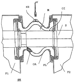
Figure 1: The bus bar connection with a connecting sleeve according to the
present
invention, in cross section;

Figure 2: The connecting sleeve according to the present invention, in a
different
cross section.
Detailed Description of the Preferred Embodiments
Figure 1 is a cross section through a bus bar connection SK that is intended
to connect
two switchboard sections Fl, F2 (left-hand and right-hand parts of the
drawing,
respectively).

There are bus bar tubes S in the gas containers of the two switchboard
sections F1 and
F2; one end of each of these extends from the gas container so that they can
be
connected to one another through the bus bar connection SK. To this end, the
bus bar
tubes S are coaxial to each other, and the ends of each of them extend from an

3


CA 02501143 2005-04-04
WO 2004/034535
PCT/EP2003/009081
opening that is sealed off by sealing rings (0-rings). All of the leadthroughs
are
located on a container support and are sealed by O-rings so as to prevent the
egress of
insulating gas. One bus bar tube S of the second switchboard section F2 (right-
hand
part of the drawing) extends further out of its opening than the corresponding
part of
the first bus bar tube (left-hand part of the drawing).

A connecting sleeve M extends around the bus bar ends (ends of the bus bar
tubes S),
and this is in the form of a tube and of an elastic insulating material I,
preferably an
elastomer. The sleeve M is secured to the outer wall of the switchboard
sections F1
and F2 through flanges FL and encloses the parts of the bus bar that extend
beyond
the switchboard sections. The connection is electrically insulated from and
protected
against the environment by this sleeve M.

According to the present invention, the sleeve M has an inner conductive
surface 01
that is in electrical contact with the bus bar S so that its voltage potential
is applied to
this inner surface 01. In addition, the sleeve M has an outer surface OA that
is also
electrically conductive. This outside surface OA is grounded through the
flange and
the walls of the gas containers of the switchboard sections F 1 and F2.

A sensor in the form of a coupling electrode KE is incorporated in the middle
area of
the connecting sleeve M In order to capture the measurement signals during TE
UHF
measurement. The coupling electrode KE is positioned in the insulating
material I
and is formed as a concave curved surface that is tangential to the outer
surface OA.
The coupling electrode can be of a conductive material or of a semiconductor
plastic.
A contact pin is attached to the coupling electrode KE, and this pin forms
part of a
plug-type connector that is positioned in an opening and so can be connected
to
measuring equipment through a matching plug (counterpart of the connection).
Figure 2 is another cross sectional view of the sleeve M and shows the
coupling
electrode that is integrated therein more precisely.

As can be seen, the coupling electrode KE itself is imbedded in the insulating
material
I, with the edge area R of the sensor surface of the sensor surface
overlapping the
outside surface OA of the sleeve M. The electrode KE is thus separated from
the
grounded outside surface OA by a thin layer of insulating material 1. Because
of this,
and because of the tangential orientation of the sensor surface, there is no
noteworthy

4


CA 02501143 2005-04-04
WO 2004/034535
PCT/EP2003/009081
increase of the field in the area of the electrode. This entails the advantage
that the
primary capacity of the coupling electrode for the bus bar S is a function of
the sensor
surface of the electrode KE and the distance to the inside surface 01. For
this reason,
the primary capacity can be very large without affecting the dielectric
strength of the
sleeve M. Because of this, it is possible to achieve great sensitivity of the
sensor KE
to partial discharge.

Contact with the sensor KE is made through the plug-type contact Si that is
positioned within an opening A in the sleeve M and thus forms a socket in
which the
plug S2 fits exactly and is dust- and water-proof. Since the sensor KE is
accessible
from outside and is also located outside the gas chamber, not only is it very
simple to
establish a measurement contact; it is also possible to effect any replacement
of the
sensor KE that may become necessary without any difficulty.

The system as a whole contains only a few inexpensive components. No
additional
seals of the like are required, and there is no requirement for additional
space.

For this reason, the system that is proposed is well suited for use in gas-
insulated
switchboard systems. Other potential applications are possible, such as its
use in
power transformers and the like.


Representative Drawing
A single figure which represents the drawing illustrating the invention.
Administrative Status

For a clearer understanding of the status of the application/patent presented on this page, the site Disclaimer , as well as the definitions for Patent , Administrative Status , Maintenance Fee  and Payment History  should be consulted.

Administrative Status

Title Date
Forecasted Issue Date 2010-11-30
(86) PCT Filing Date 2003-08-16
(87) PCT Publication Date 2004-04-22
(85) National Entry 2005-04-04
Examination Requested 2006-09-25
(45) Issued 2010-11-30
Deemed Expired 2013-08-16

Abandonment History

There is no abandonment history.

Payment History

Fee Type Anniversary Year Due Date Amount Paid Paid Date
Registration of a document - section 124 $100.00 2005-04-04
Application Fee $400.00 2005-04-04
Maintenance Fee - Application - New Act 2 2005-08-16 $100.00 2005-06-29
Registration of a document - section 124 $100.00 2006-01-19
Maintenance Fee - Application - New Act 3 2006-08-16 $100.00 2006-07-04
Request for Examination $800.00 2006-09-25
Maintenance Fee - Application - New Act 4 2007-08-16 $100.00 2007-07-09
Maintenance Fee - Application - New Act 5 2008-08-18 $200.00 2008-08-08
Maintenance Fee - Application - New Act 6 2009-08-17 $200.00 2009-07-27
Maintenance Fee - Application - New Act 7 2010-08-16 $200.00 2010-06-25
Final Fee $300.00 2010-09-15
Maintenance Fee - Patent - New Act 8 2011-08-16 $200.00 2011-08-02
Owners on Record

Note: Records showing the ownership history in alphabetical order.

Current Owners on Record
AREVA T&D SA
Past Owners on Record
ALSTOM
RUHLAND, SIEGFRIED
STARCK, THIERRY
Past Owners that do not appear in the "Owners on Record" listing will appear in other documentation within the application.
Documents

To view selected files, please enter reCAPTCHA code :


To view images, click a link in the Document Description column. To download the documents, select one or more checkboxes in the first column and then click the "Download Selected in PDF format (Zip Archive)" or the "Download Selected as Single PDF" button.

List of published and non-published patent-specific documents on the CPD .

If you have any difficulty accessing content, you can call the Client Service Centre at 1-866-997-1936 or send them an e-mail at CIPO Client Service Centre.


Document
Description 
Date
(yyyy-mm-dd) 
Number of pages   Size of Image (KB) 
Claims 2008-12-17 2 76
Cover Page 2005-06-27 1 45
Representative Drawing 2010-11-15 1 12
Cover Page 2010-11-15 2 52
Abstract 2005-04-04 1 24
Claims 2005-04-04 2 76
Drawings 2005-04-04 2 31
Description 2005-04-04 5 259
Representative Drawing 2005-04-04 1 16
Description 2008-12-17 5 263
Abstract 2010-04-12 1 24
Claims 2009-11-03 2 72
PCT 2005-04-04 4 171
Correspondence 2005-06-21 1 27
Prosecution-Amendment 2006-09-25 1 41
PCT 2005-04-04 9 379
Assignment 2005-04-04 3 83
Fees 2005-06-29 1 31
Assignment 2006-01-19 6 163
Fees 2006-07-04 1 39
Fees 2007-07-09 1 39
Prosecution-Amendment 2008-07-03 2 41
Fees 2008-08-08 1 40
Prosecution-Amendment 2008-12-17 6 288
Prosecution-Amendment 2009-06-15 1 32
Fees 2009-07-27 1 40
Prosecution-Amendment 2009-11-03 3 106
Fees 2010-06-25 1 41
Correspondence 2010-09-15 2 50