Language selection

Search

Patent 2501161 Summary

Third-party information liability

Some of the information on this Web page has been provided by external sources. The Government of Canada is not responsible for the accuracy, reliability or currency of the information supplied by external sources. Users wishing to rely upon this information should consult directly with the source of the information. Content provided by external sources is not subject to official languages, privacy and accessibility requirements.

Claims and Abstract availability

Any discrepancies in the text and image of the Claims and Abstract are due to differing posting times. Text of the Claims and Abstract are posted:

  • At the time the application is open to public inspection;
  • At the time of issue of the patent (grant).
(12) Patent: (11) CA 2501161
(54) English Title: INNER HOUSING FOR ROTARY PISTON MACHINES
(54) French Title: BOITIER INTERNE POUR MACHINES A PISTON ROTATIF
Status: Expired and beyond the Period of Reversal
Bibliographic Data
(51) International Patent Classification (IPC):
  • F01C 03/08 (2006.01)
  • F01C 09/00 (2006.01)
  • F01C 21/10 (2006.01)
(72) Inventors :
  • ARNOLD, FELIX (Germany)
(73) Owners :
  • ROBERT BOSCH GMBH
(71) Applicants :
  • ROBERT BOSCH GMBH (Germany)
(74) Agent: SMART & BIGGAR LP
(74) Associate agent:
(45) Issued: 2010-11-23
(86) PCT Filing Date: 2003-08-04
(87) Open to Public Inspection: 2004-02-19
Examination requested: 2008-07-15
Availability of licence: N/A
Dedicated to the Public: N/A
(25) Language of filing: English

Patent Cooperation Treaty (PCT): Yes
(86) PCT Filing Number: PCT/DE2003/002632
(87) International Publication Number: DE2003002632
(85) National Entry: 2005-04-04

(30) Application Priority Data:
Application No. Country/Territory Date
102 35 604.1 (Germany) 2002-08-02

Abstracts

English Abstract


The invention relates to the rotary piston machine with an inner housing
(1) and rotors (2, 3), the axes of which are disposed at an angle to one
another in order to
equalize manufacturing tolerances and to reduce gap losses of such machines.


French Abstract

L'invention concerne une machine à piston rotatif comportant une enveloppe interne (1) et des rotors (2, 3) dont les axes forment un angle, cette conception permettant de compenser les tolérances de fabrication et de réduire les pertes d'interstices inhérentes à de telles machines.

Claims

Note: Claims are shown in the official language in which they were submitted.

CLAIMS:
1. A rotary piston machine including:
first and second rotors being mutually disposed at an axial angle,
said first rotor engaging said second rotor such that chambers are formed
between said first and second rotors for conveying fluids or gases, said
second
rotor having a shank, said shank engaging a motor shaft;
a housing including an inner surface;
an inner housing including an outer surface spaced from said inner
surface of said housing thereby forming a space therebetween, said inner
housing
further including
a cylindrical borehole in which said rotors are accommodated, said
borehole including a spherical recess having an opening through which said
shank
of said second rotor passes for engaging said motor shaft, said inner housing
being shiftable, relative to the rotors, in axial and radial directions;
first structural and biasing means for urging said inner housing
against rotation within said housing;
second structural means for preventing movement of the inner
housing in the axial direction away from the rotors; and
said inner housing including at least one pressure passage for
transferring operating pressure in said space between the outer surface of the
inner housing and the inner surface of the housing into the inner housing for
producing contacting pressure between the inner housing and the rotors for
minimizing gap flows.
2. The rotary piston machine of claim 1, further comprising:
second biasing means for moving said rotors axially towards a
motor; and

third biasing means for limiting movement of said rotors axially
towards said motor.
3. The machine of claim 2 wherein the second biasing means
comprises adjusting rings.
4. The machine of claim 2 wherein the third biasing means comprises a
split washer.
5. The machine of claim 1 wherein said first structural and biasing
means comprises:
a recesses disposed between said inner surface of the housing and
said outer surface of the inner housing; and
springs disposed on said outer surface of said inner housing, said
springs engaging said recess.
6. The machine of claim 1 wherein the second structural means
comprises a cone.
7. A rotary piston machine including:
first and second rotors mutually disposed at an axial angle, said first
rotor engaging said second rotor such that chambers are formed between said
first and second rotors for conveying fluids or gases;
an outer housing;
an inner housing including a cylindrical borehole having a recess,
said rotors being disposed in said borehole, said recess having an opening
through which said second rotor passes; and
at least one pressure passage in said inner housing for transferring
operating pressure exterior of the inner housing into the inner housing for
producing contacting pressure between said inner housing and said rotors.
6

8. The machine of claim 7 wherein said inner housing is shiftable,
relative to the rotors, in axial and radial directions.
9. The machine of claim 7 wherein said borehole recess is spherical.
7

Description

Note: Descriptions are shown in the official language in which they were submitted.


CA 02501161 2010-02-18
50783-10
INNER HOUSING FOR ROTARY PISTON MACHINES
The invention starts out from a rotary piston machine. The
manufacture of rotary piston machines with power parts and shut-off parts with
axes arranged at an angle to one another is known. For these, the rotors, at
least
one power part and one shut-off part occupy a spherical volume
(DE 42 41 320 C2) or correspond to the volume of a spherical washer
(198 37729 Al).
However, such machines have the disadvantage that, especially
when the overall dimensions become smaller, the gap losses between the regions
in the interior of such machines, which are acted upon with different
pressures and
can be used as pumps or motors, increase and, due to methods such as the
manufacture of components with lower tolerances, there is a disproportionate
increase in the manufacturing costs for producing precise, meshing rotors and
the
associated housing, as a result of which the necessary expense for centering
the
rotors relative to one another increases exponentially and it is not possible
to
reduce these gap losses at economically justifiable costs.
An aspect of the invention relates to a rotary piston machine
including: first and second rotors being mutually disposed at an axial angle,
said
first rotor engaging said second rotor such that chambers are formed between
said first and second rotors for conveying fluids or gases, said second rotor
having
a shank, said shank engaging a motor shaft; a housing including an .inner
surface;
an inner housing including an outer surface spaced from said inner surface of
said
housing thereby forming a space therebetween, said inner housing further
including a cylindrical borehole in which said rotors are accommodated, said
borehole including a spherical recess having an opening through which said
shank
of said second rotor passes for engaging said motor shaft, said inner housing
being shiftable, relative to the rotors, in axial and radial directions; first
structural
and biasing means for urging said inner housing against rotation within said
housing; second structural means for preventing movement of the inner housing
in
the axial direction away from the rotors; and said inner housing including at
least
1

CA 02501161 2010-02-18
50783-10
one pressure passage for transferring operating pressure in said space between
the outer surface of the inner housing and the inner surface of the housing
into the
inner housing for producing contacting pressure between the inner housing and
the rotors for minimizing gap flows.
Another aspect of the invention relates to a rotary piston machine
including: first and second rotors mutually disposed at an axial angle, said
first
rotor engaging said second rotor such that chambers are formed between said
first and second rotors for conveying fluids or gases; an outer housing; an
inner
housing including a cylindrical borehole having a recess, said rotors being
disposed in said borehole, said recess having an opening through which said
second rotor passes; and at least one pressure passage in said inner housing
for
transferring operating pressure exterior of the inner housing into the inner
housing
for producing contacting pressure between said inner housing and said rotors.
The inventive rotary piston machine of some embodiments of the
invention has the advantage that, due to the arrangement of the inner housing,
which can be shifted freely in the axial and radial directions, the inner
housing is
centered relative to the rotors, so that the dimensions of the gap between the
components of the rotary piston machine, which can be moved relative to one
another (power part, shut-off part, inner housing) and are arranged to form a
seal,
can be averaged, as a result of which the gap losses are reduced. This is
achieved owing to the fact that the rotors, which have a spherical external
shape
and are centered, on the one hand, by a shaft, for example, the drive shaft of
a
motor (power part) that is flanged to the rotary piston machine and, on the
other,
the control head of the rotary piston machine (shut-off part), are surrounded
by an
inner housing with a spherical
la

CA 02501161 2005-04-04
recess. With a cylindrical borehole, which goes over into the spherical
recess, the inner
housing freely movably takes up the rotor, the rotor being centered on the
shank of the
control head. The spherical recess is to accommodate the one rotor, which is
disposed on
shank and engages the other rotor, seated on the shank of the control head, at
an axial
angle. An opening in the spherical part of the inner housing permits the
shaft, as well as
the shank of the rotor (power part) fastened thereon, to be passed through. In
addition,
the inner housing is prevented from backing away from the control head, for
example, by
a cone, which surrounds the shank of the rotor rotating with the shaft, and
prevented from
rotating along by a protection against torsion, which can be shifted freely in
the axial and
radial directions, for example, by springs, which are disposed on the outside
of the inner
housing and engage recesses at the outer housing. Pressure equalization
between the
inside and the outside of the inner housing is produced through openings over
a portion
of the periphery at the inner housing which, depending on the type of
operation, function
as an inlet or an outlet of the conveying or driving fluid, so that the
pressure between the
inner housing and the housing is the same as that within the inner housing and
that the
pressure between the housing and the inner housing is higher than the static
pressure in
the gap between the outer circumferential surface of the rotors and of the
inner surface of
the inner housing during developing flow through the gap, so that, by these
means, an
additional sealing action is achieved, in that the inner housing is pressed
all around on the
rotors by the resulting pressure forces.
In accordance with a further advantageous development of the invention,
the rotors and the inner housing surrounding the rotors can be pressed against
one another
in the axial direction, for example over an adjusting ring and a spring lock
washer, so that
the amount of fluid flowing through the gaps between the individual chambers
formed by
the rotors and between the rotor, lying in the spherical recess, and the inner
housing, can
additionally be reduced.
Further advantageous developments of the invention can be inferred from
the following description of an example, the drawing and the claims,
2

CA 02501161 2010-02-18
50783-10
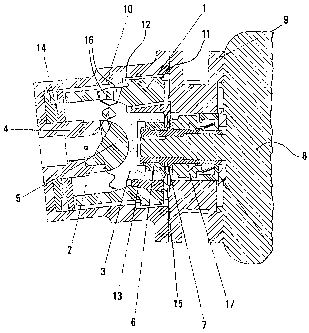
An example of the invention is shown in the drawing and explained
in greater detail in the following.
The rotors of a rotary piston machine, the shut-off part 2 and the
power part 3, engage one another at an axial angle, so that chambers are
formed
between the shut-off part 2 and the power part 3 with volumes variable over
the
angle of rotation for conveying fluids or gases. With a borehole accommodating
the shank 4 of the control head 5, the shut-off part 2 is disposed rotatably
about
the longitudinal axis of the shank 4. On the side facing the shut-off part 2,
the
power part 3 has a central, spherical recess for accommodating the control
head 5. By means of an adjusting spring 6 and a shaft extension 7, the shank
of
the power part 3 is fastened on the shaft of a motor 8. The housing 10 is
fastened
to the motor 8 over a flange 9. The two rotors (shut-off part 2 and power part
3),
which are fixed in their position by the shank 4 of the control head 5 and the
shaft
of the motor 8, are surrounded by an inner housing 1, which can be shifted in
the
axial and radial directions and has a central borehole, which goes over into a
spherical recess, for accommodating the rotors (shut-off part 2 and power part
3).
In order to prevent the inner housing 1 from rotating along, springs 1,1,
which
engage recesses 12 at the housing 10, are formed at the outside of the inner
housing 1. Above the shank of the power part 3, a cone 13 is disposed, which
prevents movement of the inner housing 1 away from the control head 5. The
shut-off part 2, the power part 3 and the inner housing 1 are pressed against
one
another in an axial direction by adjusting rings 14 and a split washer 15. Due
to
the free displaceability of the inner housing 1 relative to the rotors 2 and
3,
manufacturing tolerances of the sub-assembly as a whole, especially of the
shut-
off part 2 and the power part 3 are averaged and, as a result, gap flows are
reduced. The operating pressure of the rotary piston machine in the space
between the housing 10 and the inner housing 1 is transferred though openings
16 into the inner housing 1. By these means, an additional force is produced,
with
which the inner housing 1 is pressed in the radial and axial directions
against the
shut-off part 2 and the power part 3. In order to prevent loss of conveying
fluid
from the housing 10, a mechanical seal 17 is disposed between the flange 9 and
the shaft of the motor 8.
3

CA 02501161 2005-04-04
All the distinguishing features, given in the specification, the following
claims and the drawing, may be essential to the invention individually as well
as in any
combination,
a

Representative Drawing
A single figure which represents the drawing illustrating the invention.
Administrative Status

2024-08-01:As part of the Next Generation Patents (NGP) transition, the Canadian Patents Database (CPD) now contains a more detailed Event History, which replicates the Event Log of our new back-office solution.

Please note that "Inactive:" events refers to events no longer in use in our new back-office solution.

For a clearer understanding of the status of the application/patent presented on this page, the site Disclaimer , as well as the definitions for Patent , Event History , Maintenance Fee  and Payment History  should be consulted.

Event History

Description Date
Time Limit for Reversal Expired 2023-02-06
Letter Sent 2022-08-04
Letter Sent 2022-02-04
Letter Sent 2021-08-04
Inactive: COVID 19 - Deadline extended 2020-07-16
Common Representative Appointed 2019-10-30
Inactive: Office letter 2012-08-14
Grant by Issuance 2010-11-23
Inactive: Cover page published 2010-11-22
Pre-grant 2010-09-03
Inactive: Final fee received 2010-09-03
Notice of Allowance is Issued 2010-04-28
Letter Sent 2010-04-28
Notice of Allowance is Issued 2010-04-28
Inactive: Approved for allowance (AFA) 2010-04-26
Letter Sent 2010-04-07
Amendment Received - Voluntary Amendment 2010-02-18
Inactive: Multiple transfers 2010-01-20
Inactive: S.30(2) Rules - Examiner requisition 2009-08-18
Letter Sent 2008-09-19
Amendment Received - Voluntary Amendment 2008-08-07
Request for Examination Received 2008-07-15
Request for Examination Requirements Determined Compliant 2008-07-15
All Requirements for Examination Determined Compliant 2008-07-15
Letter Sent 2006-05-05
Inactive: Correspondence - Transfer 2006-04-13
Inactive: Single transfer 2006-04-04
Inactive: Courtesy letter - Evidence 2005-06-28
Inactive: Cover page published 2005-06-23
Inactive: Notice - National entry - No RFE 2005-06-21
Application Received - PCT 2005-04-22
National Entry Requirements Determined Compliant 2005-04-04
Application Published (Open to Public Inspection) 2004-02-19

Abandonment History

There is no abandonment history.

Maintenance Fee

The last payment was received on 2010-04-23

Note : If the full payment has not been received on or before the date indicated, a further fee may be required which may be one of the following

  • the reinstatement fee;
  • the late payment fee; or
  • additional fee to reverse deemed expiry.

Patent fees are adjusted on the 1st of January every year. The amounts above are the current amounts if received by December 31 of the current year.
Please refer to the CIPO Patent Fees web page to see all current fee amounts.

Owners on Record

Note: Records showing the ownership history in alphabetical order.

Current Owners on Record
ROBERT BOSCH GMBH
Past Owners on Record
FELIX ARNOLD
Past Owners that do not appear in the "Owners on Record" listing will appear in other documentation within the application.
Documents

To view selected files, please enter reCAPTCHA code :


To view images, click a link in the Document Description column. To download the documents, select one or more checkboxes in the first column and then click the "Download Selected in PDF format (Zip Archive)" or the "Download Selected as Single PDF" button.

List of published and non-published patent-specific documents on the CPD .

If you have any difficulty accessing content, you can call the Client Service Centre at 1-866-997-1936 or send them an e-mail at CIPO Client Service Centre.


Document
Description 
Date
(yyyy-mm-dd) 
Number of pages   Size of Image (KB) 
Abstract 2005-04-03 1 8
Description 2005-04-03 4 158
Representative drawing 2005-04-03 1 38
Drawings 2005-04-03 1 43
Claims 2005-04-03 1 30
Description 2010-02-17 5 212
Claims 2010-02-17 3 74
Drawings 2010-02-17 1 41
Abstract 2010-04-27 1 8
Representative drawing 2010-11-02 1 27
Notice of National Entry 2005-06-20 1 191
Request for evidence or missing transfer 2006-04-04 1 103
Courtesy - Certificate of registration (related document(s)) 2006-05-04 1 128
Reminder - Request for Examination 2008-04-06 1 119
Acknowledgement of Request for Examination 2008-09-18 1 176
Courtesy - Certificate of registration (related document(s)) 2010-04-06 1 103
Commissioner's Notice - Application Found Allowable 2010-04-27 1 164
Commissioner's Notice - Maintenance Fee for a Patent Not Paid 2021-09-14 1 554
Courtesy - Patent Term Deemed Expired 2022-03-03 1 548
Commissioner's Notice - Maintenance Fee for a Patent Not Paid 2022-09-14 1 540
PCT 2005-04-03 7 239
Correspondence 2005-06-20 1 26
Correspondence 2010-09-02 1 38
Correspondence 2012-08-14 1 16