Sélection de la langue

Search

Sommaire du brevet 2501161 

Énoncé de désistement de responsabilité concernant l'information provenant de tiers

Une partie des informations de ce site Web a été fournie par des sources externes. Le gouvernement du Canada n'assume aucune responsabilité concernant la précision, l'actualité ou la fiabilité des informations fournies par les sources externes. Les utilisateurs qui désirent employer cette information devraient consulter directement la source des informations. Le contenu fourni par les sources externes n'est pas assujetti aux exigences sur les langues officielles, la protection des renseignements personnels et l'accessibilité.

Disponibilité de l'Abrégé et des Revendications

L'apparition de différences dans le texte et l'image des Revendications et de l'Abrégé dépend du moment auquel le document est publié. Les textes des Revendications et de l'Abrégé sont affichés :

  • lorsque la demande peut être examinée par le public;
  • lorsque le brevet est émis (délivrance).
(12) Brevet: (11) CA 2501161
(54) Titre français: BOITIER INTERNE POUR MACHINES A PISTON ROTATIF
(54) Titre anglais: INNER HOUSING FOR ROTARY PISTON MACHINES
Statut: Périmé et au-delà du délai pour l’annulation
Données bibliographiques
(51) Classification internationale des brevets (CIB):
  • F01C 3/08 (2006.01)
  • F01C 9/00 (2006.01)
  • F01C 21/10 (2006.01)
(72) Inventeurs :
  • ARNOLD, FELIX (Allemagne)
(73) Titulaires :
  • ROBERT BOSCH GMBH
(71) Demandeurs :
  • ROBERT BOSCH GMBH (Allemagne)
(74) Agent: SMART & BIGGAR LP
(74) Co-agent:
(45) Délivré: 2010-11-23
(86) Date de dépôt PCT: 2003-08-04
(87) Mise à la disponibilité du public: 2004-02-19
Requête d'examen: 2008-07-15
Licence disponible: S.O.
Cédé au domaine public: S.O.
(25) Langue des documents déposés: Anglais

Traité de coopération en matière de brevets (PCT): Oui
(86) Numéro de la demande PCT: PCT/DE2003/002632
(87) Numéro de publication internationale PCT: WO 2004015245
(85) Entrée nationale: 2005-04-04

(30) Données de priorité de la demande:
Numéro de la demande Pays / territoire Date
102 35 604.1 (Allemagne) 2002-08-02

Abrégés

Abrégé français

L'invention concerne une machine à piston rotatif comportant une enveloppe interne (1) et des rotors (2, 3) dont les axes forment un angle, cette conception permettant de compenser les tolérances de fabrication et de réduire les pertes d'interstices inhérentes à de telles machines.


Abrégé anglais


The invention relates to the rotary piston machine with an inner housing
(1) and rotors (2, 3), the axes of which are disposed at an angle to one
another in order to
equalize manufacturing tolerances and to reduce gap losses of such machines.

Revendications

Note : Les revendications sont présentées dans la langue officielle dans laquelle elles ont été soumises.


CLAIMS:
1. A rotary piston machine including:
first and second rotors being mutually disposed at an axial angle,
said first rotor engaging said second rotor such that chambers are formed
between said first and second rotors for conveying fluids or gases, said
second
rotor having a shank, said shank engaging a motor shaft;
a housing including an inner surface;
an inner housing including an outer surface spaced from said inner
surface of said housing thereby forming a space therebetween, said inner
housing
further including
a cylindrical borehole in which said rotors are accommodated, said
borehole including a spherical recess having an opening through which said
shank
of said second rotor passes for engaging said motor shaft, said inner housing
being shiftable, relative to the rotors, in axial and radial directions;
first structural and biasing means for urging said inner housing
against rotation within said housing;
second structural means for preventing movement of the inner
housing in the axial direction away from the rotors; and
said inner housing including at least one pressure passage for
transferring operating pressure in said space between the outer surface of the
inner housing and the inner surface of the housing into the inner housing for
producing contacting pressure between the inner housing and the rotors for
minimizing gap flows.
2. The rotary piston machine of claim 1, further comprising:
second biasing means for moving said rotors axially towards a
motor; and

third biasing means for limiting movement of said rotors axially
towards said motor.
3. The machine of claim 2 wherein the second biasing means
comprises adjusting rings.
4. The machine of claim 2 wherein the third biasing means comprises a
split washer.
5. The machine of claim 1 wherein said first structural and biasing
means comprises:
a recesses disposed between said inner surface of the housing and
said outer surface of the inner housing; and
springs disposed on said outer surface of said inner housing, said
springs engaging said recess.
6. The machine of claim 1 wherein the second structural means
comprises a cone.
7. A rotary piston machine including:
first and second rotors mutually disposed at an axial angle, said first
rotor engaging said second rotor such that chambers are formed between said
first and second rotors for conveying fluids or gases;
an outer housing;
an inner housing including a cylindrical borehole having a recess,
said rotors being disposed in said borehole, said recess having an opening
through which said second rotor passes; and
at least one pressure passage in said inner housing for transferring
operating pressure exterior of the inner housing into the inner housing for
producing contacting pressure between said inner housing and said rotors.
6

8. The machine of claim 7 wherein said inner housing is shiftable,
relative to the rotors, in axial and radial directions.
9. The machine of claim 7 wherein said borehole recess is spherical.
7

Description

Note : Les descriptions sont présentées dans la langue officielle dans laquelle elles ont été soumises.

CA 02501161 2010-02-18
50783-10
INNER HOUSING FOR ROTARY PISTON MACHINES
The invention starts out from a rotary piston machine. The
manufacture of rotary piston machines with power parts and shut-off parts with
axes arranged at an angle to one another is known. For these, the rotors, at
least
one power part and one shut-off part occupy a spherical volume
(DE 42 41 320 C2) or correspond to the volume of a spherical washer
(198 37729 Al).
However, such machines have the disadvantage that, especially
when the overall dimensions become smaller, the gap losses between the regions
in the interior of such machines, which are acted upon with different
pressures and
can be used as pumps or motors, increase and, due to methods such as the
manufacture of components with lower tolerances, there is a disproportionate
increase in the manufacturing costs for producing precise, meshing rotors and
the
associated housing, as a result of which the necessary expense for centering
the
rotors relative to one another increases exponentially and it is not possible
to
reduce these gap losses at economically justifiable costs.
An aspect of the invention relates to a rotary piston machine
including: first and second rotors being mutually disposed at an axial angle,
said
first rotor engaging said second rotor such that chambers are formed between
said first and second rotors for conveying fluids or gases, said second rotor
having
a shank, said shank engaging a motor shaft; a housing including an .inner
surface;
an inner housing including an outer surface spaced from said inner surface of
said
housing thereby forming a space therebetween, said inner housing further
including a cylindrical borehole in which said rotors are accommodated, said
borehole including a spherical recess having an opening through which said
shank
of said second rotor passes for engaging said motor shaft, said inner housing
being shiftable, relative to the rotors, in axial and radial directions; first
structural
and biasing means for urging said inner housing against rotation within said
housing; second structural means for preventing movement of the inner housing
in
the axial direction away from the rotors; and said inner housing including at
least
1

CA 02501161 2010-02-18
50783-10
one pressure passage for transferring operating pressure in said space between
the outer surface of the inner housing and the inner surface of the housing
into the
inner housing for producing contacting pressure between the inner housing and
the rotors for minimizing gap flows.
Another aspect of the invention relates to a rotary piston machine
including: first and second rotors mutually disposed at an axial angle, said
first
rotor engaging said second rotor such that chambers are formed between said
first and second rotors for conveying fluids or gases; an outer housing; an
inner
housing including a cylindrical borehole having a recess, said rotors being
disposed in said borehole, said recess having an opening through which said
second rotor passes; and at least one pressure passage in said inner housing
for
transferring operating pressure exterior of the inner housing into the inner
housing
for producing contacting pressure between said inner housing and said rotors.
The inventive rotary piston machine of some embodiments of the
invention has the advantage that, due to the arrangement of the inner housing,
which can be shifted freely in the axial and radial directions, the inner
housing is
centered relative to the rotors, so that the dimensions of the gap between the
components of the rotary piston machine, which can be moved relative to one
another (power part, shut-off part, inner housing) and are arranged to form a
seal,
can be averaged, as a result of which the gap losses are reduced. This is
achieved owing to the fact that the rotors, which have a spherical external
shape
and are centered, on the one hand, by a shaft, for example, the drive shaft of
a
motor (power part) that is flanged to the rotary piston machine and, on the
other,
the control head of the rotary piston machine (shut-off part), are surrounded
by an
inner housing with a spherical
la

CA 02501161 2005-04-04
recess. With a cylindrical borehole, which goes over into the spherical
recess, the inner
housing freely movably takes up the rotor, the rotor being centered on the
shank of the
control head. The spherical recess is to accommodate the one rotor, which is
disposed on
shank and engages the other rotor, seated on the shank of the control head, at
an axial
angle. An opening in the spherical part of the inner housing permits the
shaft, as well as
the shank of the rotor (power part) fastened thereon, to be passed through. In
addition,
the inner housing is prevented from backing away from the control head, for
example, by
a cone, which surrounds the shank of the rotor rotating with the shaft, and
prevented from
rotating along by a protection against torsion, which can be shifted freely in
the axial and
radial directions, for example, by springs, which are disposed on the outside
of the inner
housing and engage recesses at the outer housing. Pressure equalization
between the
inside and the outside of the inner housing is produced through openings over
a portion
of the periphery at the inner housing which, depending on the type of
operation, function
as an inlet or an outlet of the conveying or driving fluid, so that the
pressure between the
inner housing and the housing is the same as that within the inner housing and
that the
pressure between the housing and the inner housing is higher than the static
pressure in
the gap between the outer circumferential surface of the rotors and of the
inner surface of
the inner housing during developing flow through the gap, so that, by these
means, an
additional sealing action is achieved, in that the inner housing is pressed
all around on the
rotors by the resulting pressure forces.
In accordance with a further advantageous development of the invention,
the rotors and the inner housing surrounding the rotors can be pressed against
one another
in the axial direction, for example over an adjusting ring and a spring lock
washer, so that
the amount of fluid flowing through the gaps between the individual chambers
formed by
the rotors and between the rotor, lying in the spherical recess, and the inner
housing, can
additionally be reduced.
Further advantageous developments of the invention can be inferred from
the following description of an example, the drawing and the claims,
2

CA 02501161 2010-02-18
50783-10
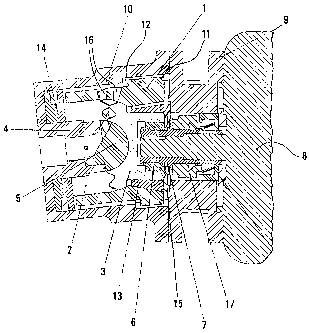
An example of the invention is shown in the drawing and explained
in greater detail in the following.
The rotors of a rotary piston machine, the shut-off part 2 and the
power part 3, engage one another at an axial angle, so that chambers are
formed
between the shut-off part 2 and the power part 3 with volumes variable over
the
angle of rotation for conveying fluids or gases. With a borehole accommodating
the shank 4 of the control head 5, the shut-off part 2 is disposed rotatably
about
the longitudinal axis of the shank 4. On the side facing the shut-off part 2,
the
power part 3 has a central, spherical recess for accommodating the control
head 5. By means of an adjusting spring 6 and a shaft extension 7, the shank
of
the power part 3 is fastened on the shaft of a motor 8. The housing 10 is
fastened
to the motor 8 over a flange 9. The two rotors (shut-off part 2 and power part
3),
which are fixed in their position by the shank 4 of the control head 5 and the
shaft
of the motor 8, are surrounded by an inner housing 1, which can be shifted in
the
axial and radial directions and has a central borehole, which goes over into a
spherical recess, for accommodating the rotors (shut-off part 2 and power part
3).
In order to prevent the inner housing 1 from rotating along, springs 1,1,
which
engage recesses 12 at the housing 10, are formed at the outside of the inner
housing 1. Above the shank of the power part 3, a cone 13 is disposed, which
prevents movement of the inner housing 1 away from the control head 5. The
shut-off part 2, the power part 3 and the inner housing 1 are pressed against
one
another in an axial direction by adjusting rings 14 and a split washer 15. Due
to
the free displaceability of the inner housing 1 relative to the rotors 2 and
3,
manufacturing tolerances of the sub-assembly as a whole, especially of the
shut-
off part 2 and the power part 3 are averaged and, as a result, gap flows are
reduced. The operating pressure of the rotary piston machine in the space
between the housing 10 and the inner housing 1 is transferred though openings
16 into the inner housing 1. By these means, an additional force is produced,
with
which the inner housing 1 is pressed in the radial and axial directions
against the
shut-off part 2 and the power part 3. In order to prevent loss of conveying
fluid
from the housing 10, a mechanical seal 17 is disposed between the flange 9 and
the shaft of the motor 8.
3

CA 02501161 2005-04-04
All the distinguishing features, given in the specification, the following
claims and the drawing, may be essential to the invention individually as well
as in any
combination,
a

Dessin représentatif
Une figure unique qui représente un dessin illustrant l'invention.
États administratifs

2024-08-01 : Dans le cadre de la transition vers les Brevets de nouvelle génération (BNG), la base de données sur les brevets canadiens (BDBC) contient désormais un Historique d'événement plus détaillé, qui reproduit le Journal des événements de notre nouvelle solution interne.

Veuillez noter que les événements débutant par « Inactive : » se réfèrent à des événements qui ne sont plus utilisés dans notre nouvelle solution interne.

Pour une meilleure compréhension de l'état de la demande ou brevet qui figure sur cette page, la rubrique Mise en garde , et les descriptions de Brevet , Historique d'événement , Taxes périodiques et Historique des paiements devraient être consultées.

Historique d'événement

Description Date
Le délai pour l'annulation est expiré 2023-02-06
Lettre envoyée 2022-08-04
Lettre envoyée 2022-02-04
Lettre envoyée 2021-08-04
Inactive : COVID 19 - Délai prolongé 2020-07-16
Représentant commun nommé 2019-10-30
Inactive : Lettre officielle 2012-08-14
Accordé par délivrance 2010-11-23
Inactive : Page couverture publiée 2010-11-22
Préoctroi 2010-09-03
Inactive : Taxe finale reçue 2010-09-03
Un avis d'acceptation est envoyé 2010-04-28
Lettre envoyée 2010-04-28
Un avis d'acceptation est envoyé 2010-04-28
Inactive : Approuvée aux fins d'acceptation (AFA) 2010-04-26
Lettre envoyée 2010-04-07
Modification reçue - modification volontaire 2010-02-18
Inactive : Transferts multiples 2010-01-20
Inactive : Dem. de l'examinateur par.30(2) Règles 2009-08-18
Lettre envoyée 2008-09-19
Modification reçue - modification volontaire 2008-08-07
Requête d'examen reçue 2008-07-15
Exigences pour une requête d'examen - jugée conforme 2008-07-15
Toutes les exigences pour l'examen - jugée conforme 2008-07-15
Lettre envoyée 2006-05-05
Inactive : Correspondance - Transfert 2006-04-13
Inactive : Transfert individuel 2006-04-04
Inactive : Lettre de courtoisie - Preuve 2005-06-28
Inactive : Page couverture publiée 2005-06-23
Inactive : Notice - Entrée phase nat. - Pas de RE 2005-06-21
Demande reçue - PCT 2005-04-22
Exigences pour l'entrée dans la phase nationale - jugée conforme 2005-04-04
Demande publiée (accessible au public) 2004-02-19

Historique d'abandonnement

Il n'y a pas d'historique d'abandonnement

Taxes périodiques

Le dernier paiement a été reçu le 2010-04-23

Avis : Si le paiement en totalité n'a pas été reçu au plus tard à la date indiquée, une taxe supplémentaire peut être imposée, soit une des taxes suivantes :

  • taxe de rétablissement ;
  • taxe pour paiement en souffrance ; ou
  • taxe additionnelle pour le renversement d'une péremption réputée.

Veuillez vous référer à la page web des taxes sur les brevets de l'OPIC pour voir tous les montants actuels des taxes.

Titulaires au dossier

Les titulaires actuels et antérieures au dossier sont affichés en ordre alphabétique.

Titulaires actuels au dossier
ROBERT BOSCH GMBH
Titulaires antérieures au dossier
FELIX ARNOLD
Les propriétaires antérieurs qui ne figurent pas dans la liste des « Propriétaires au dossier » apparaîtront dans d'autres documents au dossier.
Documents

Pour visionner les fichiers sélectionnés, entrer le code reCAPTCHA :


Pour visualiser une image, cliquer sur un lien dans la colonne description du document. Pour télécharger l'image (les images), cliquer l'une ou plusieurs cases à cocher dans la première colonne et ensuite cliquer sur le bouton "Télécharger sélection en format PDF (archive Zip)" ou le bouton "Télécharger sélection (en un fichier PDF fusionné)".

Liste des documents de brevet publiés et non publiés sur la BDBC .

Si vous avez des difficultés à accéder au contenu, veuillez communiquer avec le Centre de services à la clientèle au 1-866-997-1936, ou envoyer un courriel au Centre de service à la clientèle de l'OPIC.


Description du
Document 
Date
(aaaa-mm-jj) 
Nombre de pages   Taille de l'image (Ko) 
Abrégé 2005-04-04 1 8
Description 2005-04-04 4 158
Dessin représentatif 2005-04-04 1 38
Dessins 2005-04-04 1 43
Revendications 2005-04-04 1 30
Page couverture 2005-06-23 1 52
Description 2010-02-18 5 212
Revendications 2010-02-18 3 74
Dessins 2010-02-18 1 41
Abrégé 2010-04-28 1 8
Dessin représentatif 2010-11-03 1 27
Page couverture 2010-11-03 1 52
Avis d'entree dans la phase nationale 2005-06-21 1 191
Demande de preuve ou de transfert manquant 2006-04-05 1 103
Courtoisie - Certificat d'enregistrement (document(s) connexe(s)) 2006-05-05 1 128
Rappel - requête d'examen 2008-04-07 1 119
Accusé de réception de la requête d'examen 2008-09-19 1 176
Courtoisie - Certificat d'enregistrement (document(s) connexe(s)) 2010-04-07 1 103
Avis du commissaire - Demande jugée acceptable 2010-04-28 1 164
Avis du commissaire - Non-paiement de la taxe pour le maintien en état des droits conférés par un brevet 2021-09-15 1 554
Courtoisie - Brevet réputé périmé 2022-03-04 1 548
Avis du commissaire - Non-paiement de la taxe pour le maintien en état des droits conférés par un brevet 2022-09-15 1 540
PCT 2005-04-04 7 239
Correspondance 2005-06-21 1 26
Correspondance 2010-09-03 1 38
Correspondance 2012-08-15 1 16