Language selection

Search

Patent 2501263 Summary

Third-party information liability

Some of the information on this Web page has been provided by external sources. The Government of Canada is not responsible for the accuracy, reliability or currency of the information supplied by external sources. Users wishing to rely upon this information should consult directly with the source of the information. Content provided by external sources is not subject to official languages, privacy and accessibility requirements.

Claims and Abstract availability

Any discrepancies in the text and image of the Claims and Abstract are due to differing posting times. Text of the Claims and Abstract are posted:

  • At the time the application is open to public inspection;
  • At the time of issue of the patent (grant).
(12) Patent: (11) CA 2501263
(54) English Title: METHOD AND SYSTEM FOR ENSURING THAT A TRAIN DOES NOT PASS AN IMPROPERLY CONFIGURED DEVICE
(54) French Title: PROCEDE ET SYSTEME PERMETTANT DE S'ASSURER QU'UN TRAIN NE PASSE PAS UN DISPOSITIF NON CORRECTEMENT CONFIGURE
Status: Expired
Bibliographic Data
(51) International Patent Classification (IPC):
  • B61L 3/12 (2006.01)
  • B61L 29/22 (2006.01)
  • G05D 1/00 (2006.01)
(72) Inventors :
  • KANE, MARK EDWARD (United States of America)
  • SHOCKLEY, JAMES FRANCIS (United States of America)
  • HICKENLOOPER, HARRISON THOMAS (United States of America)
(73) Owners :
  • SIEMENS INDUSTRY, INC. (United States of America)
(71) Applicants :
  • QUANTUM ENGINEERING, INC. (United States of America)
(74) Agent: SMART & BIGGAR LP
(74) Associate agent:
(45) Issued: 2010-06-29
(86) PCT Filing Date: 2003-10-10
(87) Open to Public Inspection: 2004-04-22
Examination requested: 2006-07-10
Availability of licence: N/A
(25) Language of filing: English

Patent Cooperation Treaty (PCT): Yes
(86) PCT Filing Number: PCT/US2003/032425
(87) International Publication Number: WO2004/034167
(85) National Entry: 2005-04-01

(30) Application Priority Data:
Application No. Country/Territory Date
10/267,959 United States of America 2002-10-10

Abstracts

English Abstract


A train control system includes a positioning system and consults a database
to determine when the train is approaching a configurable device such as a
switch or grade crossing gate. The system continuously interrogates the device
to determine its status as the train approaches the device, and forces an
engineer/conductor to acknowledge any detected malfunction. The train is
forced to come to a complete stop before proceeding past the device or may be
slowed down to a speed that will allow the engineer/conductor to visually
determine whether it is safe to proceed past the device if the
engineer/conductor acknowledges a message warning of the malfunction and will
stop the train if the engineer/conductor fails to acknowledge the warning
message.


French Abstract

Un système de commande de train comprend un système de positionnement et consulte une base de données pour déterminer à quel moment le train va approcher un dispositif configurable tel qu'un commutateur ou une barrière de passage à niveau. Le système continue d'interroger le dispositif pour déterminer son état lorsque le train approche du dispositif et oblige l'ingénieur/le conducteur à accuser réception de tout dysfonctionnement détecté. Le train est amené à l'arrêt complet avant de passer devant le dispositif ou peut être ralenti à une vitesse qui permettra à l'ingénieur/au conducteur de déterminer visuellement s'il est prudent de passer devant le dispositif si l'ingénieur/le conducteur accuse réception d'un message avertissant du dysfonctionnement, et arrêtera le train si l'ingénieur/le conducteur omet d'accuser réception du message d'alarme.

Claims

Note: Claims are shown in the official language in which they were submitted.


WHAT IS CLAIMED IS:
1. A system for controlling a train, the system comprising:
a control unit; and
a transceiver, the transceiver being located on the train and being in
communication with the control unit;
wherein the control unit is configured to perform the steps of
transmitting an interrogation message to a configurable device near
the train;
listening for a response from the configurable device, the response
including a configuration of the configurable device;
allowing the train to continue if a response with a correct
configuration is received within a period of time; and
stopping the train otherwise.
2. The system of Claim 1, wherein the device is a grade crossing gate.
3. The system of Claim 1, wherein the device is a switch.
4. The system of Claim 1, wherein the response includes an identification
number of the device and wherein the control unit is further configured to
perform
the step of confirming that identification number received in the response
corresponds to the device to which the interrogation message was directed.
5. The system of Claim 1, wherein the interrogation message includes an
identification number of a device for which the interrogation message is
intended.
6. The system of Claim 1, further comprising:
a positioning system, the positioning system being in communications with
the control unit and being configured to provide position information to the
control
unit; and
a database, the database including a plurality of locations for a plurality of
configurable devices;
wherein the control unit is further configured to perform the steps of
-10-


identifying a configurable device in the database which is a next
device which the train will pass based on information from the positioning
system;
and
obtaining an identification number from the database associated
with the device identified in the identifying step.
7. The system of Claim 6, wherein the control unit is configured to
transmit the interrogation message when a distance between the train's
location
and the configurable device identified in the identifying step is below a
threshold.
8. The system of Claim 7, wherein the threshold is a predetermined
number based at least in part on an expected worst case distance required to
stop
the train.
9. The system of Claim 7, wherein the threshold is determined dynamically
based at least in part upon the current speed of the train.
10. The system of Claim 9, wherein the threshold is further based on a
weight of the train.
11. The system of Claim 9, wherein the database further includes a grade
of a track between the train and the device and the threshold is further based
on the
grade of the track between the train and the device.
12. The system of Claim 11, wherein the threshold is further based on
distribution of weight in the train.
13. The system of Claim 1, further comprising a warning device connected
to the control unit, wherein the control unit is further configured to
activate the
warning device when a response with a correct configuration is not received.
14. The system of Claim 13, wherein the control unit is further configured
to perform the step of preventing the train from moving until an
acknowledgment
of the activated warning device has been received.
15. A method for controlling a train comprising the steps of:
transmitting an interrogation message to a configurable device near the
train;
-11-


listening for a response from the configurable device, the response
including a configuration of the configurable device;
allowing the train to continue if a response with a correct configuration is
received; and
stopping the train otherwise.
16. The method of Claim 15, wherein the device is a grade crossing gate.
17. The method of Claim 15, wherein the device is a switch.
18. The method of Claim 16, further comprising the steps of storing route
information from a dispatcher in a memory and determining whether the switch
is
properly configured by comparing an actual direction of the switch to a
desired
direction of the switch based on the route information.
19. The method of Claim 15, wherein the response includes an
identification number of the device and the method further comprises the step
of
confirming that identification number received in the response corresponds to
the
device to which the interrogation message was directed.
20. The method of Claim 15, wherein the interrogation message includes
an identification number of a device for which the interrogation message is
intended.
21. The method of Claim 15, further comprising the steps of:
identifying a configurable device in a database which is a next device
which the train will pass based on information from a positioning system
located
on the train; and
obtaining an identification number associated with the device identified in
the identifying step from the database.
22. The method of Claim 21, wherein the interrogation message is
transmitted when a distance between the train's location and the configurable
device identified in the identifying step is below a threshold.
23. The method of Claim 22, wherein the threshold is a predetermined
number based at least in part on an expected worst case distance required to
stop
the train.
-12-


24. The method of Claim 22, wherein the threshold is determined
dynamically based at least in part upon the current speed of the train.
25. The method of Claim 24, wherein the threshold is further based on a
weight of the train.
26. The method of Claim 24, wherein the database further includes a grade
of a track between the train and the device and the threshold is further based
on the
grade of the track between the train and the device.
27. The method of Claim 26, wherein the threshold is further based on
distribution of weight in the train.
28. The method of Claim 15, further comprising the step of activating a
warning device when a response with a correct configuration is not received.
29. The method of Claim 28, further comprising the step of preventing the
train from moving until an acknowledgment of the activated warning device has
been received.
30. A system for controlling a train, the system comprising:
a control unit; and
a transceiver, the transceiver being located on the train and being in
communication with the control unit;
wherein the control unit is configured to perform the steps of
transmitting an interrogation message to a configurable device near
the train;
listening for a response from the configurable device, the response
including a configuration of the configurable device;
allowing the train to continue if a response with a correct
configuration is received;
if no response is received or if a response with an incorrect
configuration is received,
activating a warning device to provide a warning to a train
operator;
-13-


stopping the train if an acknowledgment of the warning is
not received or if a speed of the train is not reduced within a period of
time; and
if an acknowledgment of the warning is received within the
period of time, maintaining the speed until the device has been passed or a
verification that passing the device is acceptable has been received.
31. The system of Claim 30, wherein the device is a grade crossing gate.
32. The system of Claim 30, wherein the device is a switch.
33. The system of Claim 30, wherein the response includes an
identification number of the device and wherein the control unit is further
configured to perform the step of confirming that identification number
received in
the response corresponds to the device to which the interrogation message was
directed.
34. The system of Claim 30, wherein the interrogation message includes an
identification number of a device for which the interrogation message is
intended.
35. The system of Claim 30, further comprising:
a positioning system, the positioning system being in communications with
the control unit and being configured to provide position information to the
control
unit; and
a database, the database including a plurality of locations for a plurality of
configurable devices;
wherein the control unit is further configured to perform the steps of
identifying a configurable device in the database which is a next
device which the train will pass based on information from the positioning
system;
and
obtaining an identification number from the database associated
with the device identified in the identifying step.
36. The system of Claim 35, wherein the control unit is configured to
transmit the interrogation message when a distance between the train's
location
and the configurable device identified in the identifying step is below a
threshold.
-14-


37. The system of Claim 35, wherein the threshold is a predetermined
number based at least in part on an expected worst case distance required to
stop
the train.
38. The system of Claim 35, wherein the threshold is determined
dynamically based at least in part upon the current speed of the train.
39. The system of Claim 38, wherein the threshold is further based on a
weight of the train.
40. The system of Claim 38, wherein the database further includes a grade
of a track between the train and the device and the threshold is further based
on the
grade of the track between the train and the device.
41. The system of Claim 40, wherein the threshold is further based on
distribution of weight in the train.
42. The system of Claim 30, further comprising a warning device
connected to the control unit, wherein the control unit is further configured
to
activate the warning device when a response with a correct configuration is
not
received.
43. The system of Claim 42, wherein the control unit is further configured
to perform the step of preventing the train from moving until an
acknowledgment
of the activated warning device has been received.
44. The system of Claim 30, wherein the period of time is based on a
worst- case assumption that the train is traveling at a maximum speed and
weighs a
maximum amount.
45. The system of Claim 30, further comprising a positioning system in
communication with the control unit and located on the train, wherein the
period of
time is based on an actual speed of the train based on information reported by
the
positioning system and a weight of the train. track.
46. The system of Claim 45, further comprising a track database in
communication with the control unit, wherein the period of time is further
based on
a grade of a section of track between the train and the device.
47. A method for controlling a train comprising the steps of:
-15-


transmitting an interrogation message to a configurable device near the
train;
listening for a response from the configurable device, the response
including a configuration of the configurable device;
allowing the train to continue if a response with a correct configuration is
received;
if a response with a correct configuration is not received or if no response
is
received,
activating a warning device to provide a warning;
stopping the train if an acknowledgment of the warning is not
received or if a speed of the train is not reduced within a period of time;
and
if an acknowledgment of the warning is received within the period
of time, maintaining the speed until the device has been passed or a
verification
that passing the device is acceptable has been received.

48. The method of Claim 47, wherein the device is a grade crossing gate.

49. The method of Claim 47, wherein the device is a switch.

50. The method of Claim 47, wherein the response includes an
identification number of the device and further comprising the step of
confirming
that identification number received in the response corresponds to the device
to
which the interrogation message was directed.

51. The method of Claim 47, wherein the interrogation message includes
an identification number of a device for which the interrogation message is
intended.

52. The method of Claim 47, further comprising the steps of:
identifying a configurable device in the database which is a next device
which the train will pass based on information from a positioning system; and
obtaining an identification number associated with the device identified in
the identifying step from a database.

-16-


53. The method of Claim 52, wherein the interrogation message is
transmitted when a distance between the train's location and the configurable
device identified in the identifying step is below a threshold.

54. The method of Claim 52, wherein the threshold is a predetermined
number based at least in part on an expected worst case distance required to
stop
the train.

55. The method of Claim 52, further comprising the step of calculating the
threshold based at least in part upon the current speed of the train.

56. The method of Claim 55, wherein the threshold is further based on a
weight of the train.

57. The method of Claim 55, wherein the database further includes a grade
of a track between the train and the device and the threshold is further based
on the
grade of the track between the train and the device.

58. The method of Claim 57, wherein the threshold is further based on
distribution of weight in the train.

59. The method of Claim 47, further comprising the step of activating a
warning device when a response with a correct configuration is not received.

60. The method of Claim 59, further comprising the step of preventing the
train from moving until an acknowledgment of the activated warning device has
been received.

61. The method of Claim 47, wherein the period of time is based on a
worst- case assumption that the train is traveling at a maximum speed and
weighs a
maximum amount.

62. The method of Claim 47, wherein the period of time is based on an
actual speed of the train based on information reported by the positioning
system
and a weight of the train.

63. The method of Claim 62, wherein the period of time is further based on
a grade of a section of track between the train and the device.

64. The method of Claim 63, wherein the configurable device is a switch
and further comprising the steps of storing route information from a
dispatcher in a

-17-


memory and determining whether a configuration received from the switch is
correct by comparing a direction of the switch to a desired direction of the
switch
based on the route information.

65. A method for controlling a train comprising the steps of:
obtaining a position of a train from a positioning system;
determining a location and identification number of a next configurable
device that will be passed by the train from a database;
sending an interrogation message including the identification number of the
next configurable device;
waiting a period of time based in part on a speed and a weight of the train
and a grade of a section of track between the train and the device;
listening for a response during the period of time;
if the response is received, comparing an identification number included in
the response to the identification number of the next configurable device;
stopping the train if a response from the device indicates that the device is
not properly configured or if a response is not received within the period of
time.

66. The method of Claim 65, further comprising the step of transmitting a
command to the next configurable device, the command instructing the next
configurable device to assume a proper configuration.

67. The method of Claim 65, wherein the configurable device is a switch
and further comprising the steps of storing route information from a
dispatcher in a
memory and determining whether the switch is properly configured by comparing
a direction of the switch to a desired direction of the switch based on the
route
information.

68. A computerized method for controlling a train comprising the steps of:
obtaining a position of a train from a positioning system;
determining a location and identification number of a next configurable
device that will be passed by the train from a database;
sending an interrogation message including the identification number of the
next configurable device;

-18-


waiting a first period of time based in part on a speed and a weight of the
train and a grade of a section of track between the train and the device;
listening for a response during the first period of time;
if the response is received, comparing an identification number included in
the response to the identification number of the next configurable device;
providing a warning to an operator if a response from the device indicates
that the device is not properly configured or if a response is not received
within the
first period of time;
stopping the train if the operator does not acknowledge the warning and
slow the train to a reduced speed within a second period of time; and
if the warning is acknowledged and the reduced speed is achieved within
the second period of time, maintaining the reduced speed until the operator
verifies
that the device is configured properly or until the train has passed the
device;

69. The method of Claim 68, further comprising the step of transmitting a
command to the next configurable device, the command instructing the next
configurable device to assume a proper configuration.

70. The method of Claim 68, wherein the configurable device is a switch
and further comprising the steps of storing route information from a
dispatcher in a
memory and determining whether the switch is properly configured by comparing
a direction of the switch to a desired direction of the switch based on the
route
information.

-19-


Description

Note: Descriptions are shown in the official language in which they were submitted.


CA 02501263 2005-04-O1
WO 2004/034167 PCT/US2003/032425
METHOD AND SYSTEM FOR ENSURING THAT A TRAIN
DOES NOT PASS AN IMPROPERLY CONFIGURED DEVICE
BACKGROUND OF THE INVENTION
Field of the Invention
The invention relates to railroads generally, and more particularly to a
method and system for ensuring that a train does not pass a device such as a
grade
crossing gate or a track switch when that device is not properly configured.
Discussion of the Back round
Train safety has always been a concern in the railroad industry. If anything,
this concern has increased in recent years. This concern has led to proposals
for
and development of automated, safety-enhancing systems such as Automatic Train
Control (ATC), Positive Train Control (PTC), and others. While such systems
vary in their implementation, one goal they all share is to avoid accidents.
One source of accidents is an improperly set switch. Historically, an
engineer or conductor would visually verify that a switch has been set to the
correct position. However, engineers and conductors, being human, sometimes
make mistakes, including traveling too fast such that there is not sufficient
time to
stop the train when the signal is first visible, not activating the brakes a
sufficient
distance from the switch, failing to notice that the switch has been
improperly set,
and even forgetting to loolc at the switch. The results of such mistalces can
be
disastrous.
Another source of accidents is a malfunctioning grade crossing gate. Grade
crossing gates may be triggered by radar, by a track circuit, or by a
mechazucal
switch set at a position far enough away from the crossing gate such that the
gate
will have sufficient time to go down when triggered by a train traveling at
the
maximum allowable speed. Some gates are equipped with monitoring equipment


CA 02501263 2005-04-O1
WO 2004/034167 PCT/US2003/032425
that can determine if the gate is malfunctioning and, in some cases, sends a
message via telephone or radio informing the dispatcher of a malfwction. The
dispatcher is then required to broadcast this information to all other trains
that pass
the grade crossing.
What is needed is a method and apparatus that ensures that a train will not
pass a switch, grade crossing gate, or other device that is not properly
configured.
SUMMARY OF THE INVENTION
The present invention meets the aforementioned need to a great extent by
providing a computerized train control system in which a control module
determines a position of a train using a positioning system such as a global
positioning system (GPS), consults a database to determine when the train is
approaching a configurable device such as a switch or grade crossing gate,
continuously interrogates the device to determine its status as the train
approaches
the device, and forces an engineer/conductor to acknowledge any detected
malfunction. A malfunction can be reported by the device itself, or can be
declared
by the system if the device fails to respond to initial or subsequent
interrogations.
In some embodiments of the invention, the train is forced to come to a
complete
stop before proceeding past the device. In other embodiments, the train will
slow
to a speed that will allow the engineer/conductor to visually determine
whether it is
safe to proceed past the device if the engineer/conductor acknowledges a
message
warning of the malfunction and will stop the train if the engineer/conductor
fails to
acknowledge the warning message.
BRIEF DESCRIPTION OF THE DRAWINGS
A more complete appreciation of the invention and many of the attendant
features and advantages thereof will be readily obtained as the same become
better
understood by reference to the following detailed description when considered
in
connection with the accompanying drawings, wherein:
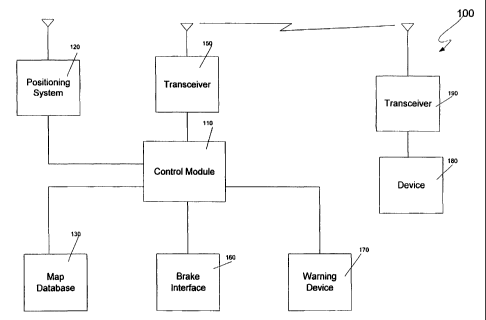
Figure 1 is a logical block diagram of a train control system according to
one embodiment of the invention.
-2-


CA 02501263 2005-04-O1
WO 2004/034167 PCT/US2003/032425
Figure 2 is a flow chart of a device interrogation method according to
another embodiment of the invention.
Figures 3a and 3b are a flow chart of a device interrogation method
according to a third embodiment of the invention.
DETAILED DESCRIPTION OF PREFERRED EMBODIMENTS
The present invention will be discussed with reference to preferred
embodiments of train control systems. Specific details, such as specific
algorithms
and hardware, are set forth in order to provide a thorough understanding of
the
present invention. The preferred embodiments discussed herein should not be
understood to limit the invention. Furthermore, for ease of understanding,
certain
method steps are delineated as separate steps; however, these steps should not
be
construed as necessarily distinct nor order dependent in their performance.
Referring now to the drawings, wherein like reference numerals designate
identical or corresponding parts throughout the several views, Figure 1 is a
logical
block diagram of a train control system 100 according to an embodiment of the
present invention. The system 100 includes a control module 110, which
typically,
but not necessarily, includes a microprocessor. The control module 110 is
responsible for controlling the other components of the system.
A positioning system 120 is connected to the control module 110. The
positioning system supplies the position (and, in some cases, the speed) of
the train
to the control module 110. The positioung can be of any type, including a
global
positioning system (GPS), a differential GPS, an inertial navigation system
(INS),
or a Loran system. Such positioning systems are well known in the art and will
not
be discussed in further detail herein. (As used herein, the term "positioning
system" refers to the portion of a positioning system that is commonly located
on a
mobile vehicle, which may or may not comprise the entire system. Thus, for
example, in connection with a global positioning system, the term "positioning
system" as used herein refers to a GPS receiver and does not include the
satellites
that transmit information to the GPS receiver.)
-3-


CA 02501263 2005-04-O1
WO 2004/034167 PCT/US2003/032425
A map database 130 is also connected to the control module 110. The map
database 130 preferably comprises a non-volatile memory such as a hard disk,
flash
memory, CD-ROM or other storage device, on which map data is stored. Other
types of memory, including volatile memory, may also be used. The map data
preferably includes positions of all configurable devices such as switches and
grade
crossing gates. The map data preferably also includes information concerning
the
direction and grade of the track in the railway. By using train position
information
obtained from the positioning system 120 as an index into the map database
140,
the control module 110 can determine its position relative to configurable
devices.
When the control module 110 determines that a configurable device 180
(which includes a transceiver 190) is present, it interrogates the device 180
through
transceiver 150. The transceiver 150 can be configured for any type of
communication, including communicating through rails and wireless. In addition
to communicating with configurable devices 180, the transceiver 150 may
communicate with a dispatcher (not shown in Figure 1).
Also connected to the control module 110 is a brake interface 160. The
brake interface 160 monitors the train brakes and allows the control module
110 to
activate and control the brakes to stop or slow the train when necessary.
A warning device 170 is also connected to the control module 110. The
warning device 170 is used to warn the conductor/engineer that a malfunction
has
been detected. The warning device 170 may also be used to allow the engineer/
conductor to acknowledge the warning. In some embodiments, the warning device
170 is in the form of button on an operator display such as the display
illustrated in
co-pending U.S. application serial number 10/186,426, entitled "Train Control
System and Method of Controlling a Train or Trains" filed July 2, 2002, the
contents of which are hereby incorporated by reference herein. In other
embodiments, the warning device 170 may be a stand alone button that
illuminates
when a malfunction is detected. In yet other embodiments (e.g., those in which
no
acknowledgment of a warning is required), the warning device 170 may comprise
or consist of a horn or other device capable of providing an audible wanmlg.
-4-


CA 02501263 2005-04-O1
WO 2004/034167 PCT/US2003/032425
Figure 2 is a flowchart 200 illustrating operation of the processor 110 in
connection with configurable devices 180. The control module 110 determines
the
train's current position from information provided by the positioning system
120 at
step 210. The control module then obtains the locations of nearby configurable
devices 180 from the map database 130 at step 212. If no configurable device
180
is withing a threshold distance, steps 210 et seq. are repeated. If a
configurable
device 180 is within a threshold distance at step 214, the device is
interrogated at
step 216.
In some embodiments, this threshold distance is predetermined distance
based in part upon a worst case assumption (i.e., an assumption that a train
having
the greatest possible weight is traveling at a maximum allowable or possible
speed
in a downhill direction on a portion of track with the steepest grade in the
system).
In other embodiments, the threshold is based on the actual speed and weight of
the
train and the grade of the track between the train and the device. In still
other
embodiments, the calculation may take into accou~it the distribution of weight
in
the train this will effect the required stopping distance as discussed in the
aforementioned co-pending IJ.S. patent application.
In some embodiments, the interrogation includes an identification number
associated with the device 180. Since only the device corresponding to the
identification number will respond to the interrogation, this identification
number
is obtained from the map database 130. This avoids contention between multiple
devices attempting to respond to the interrogation on the same frequency.
If the configurable device 180 fails to respond at step 218, or reports an
incorrect configuration at step 220, the control module notifies the
conductor/engineer of the malfunction at step 224. If, in response to the
notification, the operator fails to activate the brakes at step 226, the
control module
110 automatically activates the brakes to bring the train to a halt at step
228. At
this point, the conductor/engineer must restart the train, which preferably
requires
the conductor/engineer to aclrnowledge the warning provided at step 224.
-5-


CA 02501263 2005-04-O1
WO 2004/034167 PCT/US2003/032425
If the device 180 responds to the interrogation at step 218 and reports a
correct configuration at step 220, then, at step 222, the control module 110
returns
to step 216 if the device 180 has not been passed, or returns to step 210 to
repeat
the process for the next configurable device 180. Returning to step 216 to
interrogate the device multiple times as the train approaches the device is
important
for safety purposes. This will detect malfunctions or changes in configuration
after
the initial interrogation (e.g., someone throwing the switch into the wrong
position
after the initial interrogation but before the train reaches the switch) from
causing
and accident. Whether or not the interrogation of step 318 includes the
device's
identification number, it is preferable for the device's response to include
its
identification number as this allows for greater assurance that a response
from
some other source has not been mistaken as a response from the device.
Figures 3a and 3b together form a flowchart 300 illustrating operation of
the control unit 110 in connection with configurable devices 180 according to
a
second embodiment of the invention. Steps 310-322 of the flowchart 300 are
similar to steps 210-222 of the flowchart 200 of Figure 2; therefore, the
detailed
discussion of these steps will not be repeated. If a configurable device 180
does
not respond at step 318 or reports an incorrect configuration at step 320
after being
interrogated at step 316, the control module 110 then activates the warning
device
170 to inform the conductor/engineer of the problem at step 330. A time period
within which the operator must acknowledge the wanling and slow the train to a
reduced speed is associated with the warning. This time period may be a
predetermined number based on a worst-case stopping distance, or may be
calculated dynamically based on factors such as the current speed of the
train, the
braking characteristics of the brakes on the train, the weight of the train,
the
distribution of weight on the train, and/or the grade of the track as
determined from
the map database 130 using the train position from the positioning system 120,
or
other factors as discussed in the above-referenced co-pending U.S. patent
application.
-6-


CA 02501263 2005-04-O1
WO 2004/034167 PCT/US2003/032425
If the operator acknowledges the warning at step 332 and sufficiently
slowed the train at step 334 within the allowable time period, the control
module
110 monitors the speed of the train to ensure that the reduced speed is
maintained
at step 336 until either the train has passed the device 180 at step 338 or
the
conductor/engineer verifies that he has visually determined that the device is
configured properly at step 340. In the case of a configurable device such as
a
grade crossing gate, this allows the train to continue moving past the gate at
a slow
speed. In the case of an incorrectly thrown switch, it is expected that the
conductor/engineer will stop the train if the switch cannot be set to the
correct
position before the train reaches it; however, there may be some circumstances
in
which the conductor/engineer desires to allow the train to continue past an
incorrectly thrown switch. Because the conductor/engineer was forced to
acknowledge the warning about the improperly configured switch, it is unlikely
that allowing the train to proceed past the improperly configured switch is
not
intentional. In other embodiments, a train may not be allowed to pass the
switch
until it has come to a complete stop, but may be allowed to pass an improperly
configured grade crossing gate at a reduced speed without first coming to a
complete stop.
If the conductor/engineer fails to acknowledge the warning at step 334
within the allowed time period, the control module 110 commands the brake
interface to stop the train at step 342. The control module 110 then notifies
the
dispatcher of the stopped train at step 344.
At steps 220 and 320 above, the control module 110 determines whether
the device 180 is properly configured. This determination is necessarily
device
dependent. For example, in the case of a switch, the determination as to
whether
the device is configured correctly is preferably made with respect to
warrants/authorities and/or route information issued to the train. That is,
the
control module 110 preferably stores information as to what route the train is
to
take and what warrants (also sometimes referred to as authorities) have been
issued
for that train. In the case of a grade crossing gate, determining that the
device is


CA 02501263 2005-04-O1
WO 2004/034167 PCT/US2003/032425
configured properly comprises more than determining that the gate is in the
down
position. Many such devices are designed such that a failure results in the
gate
being placed in the down position. However, in the event of such a failure, it
can
be expected that some cars and/or pedestrians may attempt to cross the tracks
even
though the gate is down. Thus, if the crossing gate reports a malfunction, it
is
preferably treated as if it is not properly configured despite the fact that
the gates
may be reported as being in the down position.
It should be understood that any and all of the aforementioned events (e.g.,
the acknowledgment or lack thereof of a warning from an engineer/conductor,
the
stopping of the train upon a detection of an improperly configured device) may
be
recorded by the event recorder 140. It should also be understood that, in some
embodiments, some configurable devices 180 may be configured by sending
commands from the train. In such embodiments, the control module 110 will send
the appropriate command via the transceiver 150 on the train to the device 180
via
its transceiver 190.
One advantage of those embodiments of the invention in which a
configurable device is interrogated as the train approaches is that such
devices are
not required to transmit information when trains are not in the area. This
saves
power as compared to those systems in which wayside devices continuously or
periodically transmit information regardless of whether a train is close
enough to
receive such information.
In the embodiments discussed above, the control module 110 is located on
the train. It should also be noted that some or all of the functions performed
by the
control module 110 could be performed by a remotely located processing unit
such
as processing unit located at a central dispatcher. In such embodiments,
information from devices on the train (e.g., the brake interface 160) is
communicated to the remotely located processing unit via the transceiver 150.
_g_


CA 02501263 2005-04-O1
WO 2004/034167 PCT/US2003/032425
Obviously, numerous modifications and variations of the present invention
are possible in light of the above teachings. It is therefore to be understood
that
within the scope of the appended claims, the invention may be practiced
otherwise
than as specifically described herein.
-9-

Representative Drawing
A single figure which represents the drawing illustrating the invention.
Administrative Status

For a clearer understanding of the status of the application/patent presented on this page, the site Disclaimer , as well as the definitions for Patent , Administrative Status , Maintenance Fee  and Payment History  should be consulted.

Administrative Status

Title Date
Forecasted Issue Date 2010-06-29
(86) PCT Filing Date 2003-10-10
(87) PCT Publication Date 2004-04-22
(85) National Entry 2005-04-01
Examination Requested 2006-07-10
(45) Issued 2010-06-29
Expired 2023-10-10

Abandonment History

There is no abandonment history.

Payment History

Fee Type Anniversary Year Due Date Amount Paid Paid Date
Application Fee $400.00 2005-04-01
Maintenance Fee - Application - New Act 2 2005-10-11 $100.00 2005-04-01
Registration of a document - section 124 $100.00 2005-07-18
Request for Examination $800.00 2006-07-10
Maintenance Fee - Application - New Act 3 2006-10-10 $100.00 2006-08-30
Maintenance Fee - Application - New Act 4 2007-10-10 $100.00 2007-09-07
Maintenance Fee - Application - New Act 5 2008-10-10 $200.00 2008-09-23
Maintenance Fee - Application - New Act 6 2009-10-13 $200.00 2009-09-30
Final Fee $300.00 2010-01-28
Expired 2019 - Filing an Amendment after allowance $400.00 2010-01-28
Registration of a document - section 124 $100.00 2010-06-03
Maintenance Fee - Patent - New Act 7 2010-10-12 $200.00 2010-09-17
Maintenance Fee - Patent - New Act 8 2011-10-10 $200.00 2011-09-22
Maintenance Fee - Patent - New Act 9 2012-10-10 $200.00 2012-09-12
Maintenance Fee - Patent - New Act 10 2013-10-10 $250.00 2013-09-13
Registration of a document - section 124 $100.00 2014-05-26
Maintenance Fee - Patent - New Act 11 2014-10-10 $250.00 2014-09-08
Maintenance Fee - Patent - New Act 12 2015-10-13 $250.00 2015-09-09
Maintenance Fee - Patent - New Act 13 2016-10-11 $250.00 2016-09-07
Maintenance Fee - Patent - New Act 14 2017-10-10 $250.00 2017-09-07
Maintenance Fee - Patent - New Act 15 2018-10-10 $450.00 2018-09-13
Maintenance Fee - Patent - New Act 16 2019-10-10 $450.00 2019-09-05
Maintenance Fee - Patent - New Act 17 2020-10-12 $450.00 2020-09-25
Maintenance Fee - Patent - New Act 18 2021-10-11 $459.00 2021-09-13
Maintenance Fee - Patent - New Act 19 2022-10-10 $458.08 2022-09-26
Owners on Record

Note: Records showing the ownership history in alphabetical order.

Current Owners on Record
SIEMENS INDUSTRY, INC.
Past Owners on Record
HICKENLOOPER, HARRISON THOMAS
INVENSYS RAIL CORPORATION
KANE, MARK EDWARD
QUANTUM ENGINEERING, INC.
SHOCKLEY, JAMES FRANCIS
SIEMENS RAIL AUTOMATION CORPORATION
Past Owners that do not appear in the "Owners on Record" listing will appear in other documentation within the application.
Documents

To view selected files, please enter reCAPTCHA code :


To view images, click a link in the Document Description column. To download the documents, select one or more checkboxes in the first column and then click the "Download Selected in PDF format (Zip Archive)" or the "Download Selected as Single PDF" button.

List of published and non-published patent-specific documents on the CPD .

If you have any difficulty accessing content, you can call the Client Service Centre at 1-866-997-1936 or send them an e-mail at CIPO Client Service Centre.


Document
Description 
Date
(yyyy-mm-dd) 
Number of pages   Size of Image (KB) 
Cover Page 2010-06-02 2 47
Representative Drawing 2005-06-27 1 7
Cover Page 2005-06-27 1 43
Abstract 2005-04-01 1 62
Claims 2005-04-01 10 441
Drawings 2005-04-01 4 67
Description 2005-04-01 9 441
Claims 2006-07-10 14 531
Claims 2009-05-14 14 537
Description 2009-05-14 9 430
Description 2010-01-28 13 629
Correspondence 2005-06-22 1 27
PCT 2005-04-01 1 59
Assignment 2005-04-01 3 140
Assignment 2005-07-18 6 235
Prosecution-Amendment 2006-07-10 16 581
Prosecution-Amendment 2006-07-10 1 40
Prosecution-Amendment 2006-08-25 1 33
Assignment 2008-09-23 38 2,008
Prosecution-Amendment 2009-03-11 6 309
Prosecution-Amendment 2009-05-14 10 391
Correspondence 2010-01-28 2 70
Prosecution-Amendment 2010-01-28 8 336
Correspondence 2010-04-27 1 2
Assignment 2010-06-03 19 969
Correspondence 2014-09-24 1 28
Assignment 2014-05-26 9 349
Correspondence 2014-05-26 2 98
Correspondence 2014-07-25 3 120
Correspondence 2014-08-18 2 121
Correspondence 2014-08-18 1 23
Correspondence 2014-10-08 2 81
Correspondence 2014-10-17 1 23