Note: Descriptions are shown in the official language in which they were submitted.
CA 02501334 2006-07-20
WO 200x/(13529-1 PCT/US2(1(13/029780
BACKGROUND OF THE INVENTION
1. Technical Field
The present invention relates generally to the production of a puff extrudate
and,
specifically, to an improved process of producing a plurality of similarly
shaped curly puff
5 extrudate pieces from a single curly puff extrudate.
2. Description of Related Art
The production in the prior art of a puff extruded product, such as snacks
produced
and marketed under the CheetosT'" brand label, typically involves extruding a
com meal or
other dough through a die having a small orifice at extremely high pressure.
The dough
10 flashes or puffs as it exits the small orifice, thereby forming a puff
extrudate. The typical
ingredients for the starting dough may be, for example, corn meal of 41 pounds
per cubic foot
bulk density and 12 to 13.5% water content by weight. However, the starting
dough can be
based primarily on wheat flour, rice flour, soy isolate, soy concentrates, any
other cereal
flours, protein flour, or fortified flour, along with additives that might
include lecithin, oil,
15 salt, sugar, vitamin mix, soluble fibers, and insoluble fibers. The mix
typically comprises a
particle size of 100 to 1200 microns.
The puff extrusion process is illustrated in Figure 1, which is a schematic
cross-
section of a die 12 having a small diameter exit orifice 14. In manufacturing
a corn-based
puff product, corn meal is added to, typically, a single (i.e., American
Extrusion, Wenger,
20 Maddox) or twin (i.e., Wenger, Clextral, Buhler) screw-type extruder such
as a model X 25
CA 02501334 2005-04-06
WO 2004/035294 PCT/US2003/029780
manufactured by Wenger or BC45 manufactured by Clextral of the United States
and France,
respectively. Using a Cheetos like example, water is added to the corn meal
while in the
extruder, which is operated at a screw speed of 100 to 1000 RPM, in order to
bring the
overall water content of the meal up to 15% to 18%. The meal becomes a viscous
melt 10 as
it approaches the die 12 and is then forced through a very small opening or
orifice 14 in the
die 12. The diameter of the orifice 14 typically ranges between 2.0 mm and
12.0 mm for a
corn meal formulation at conventional moisture content, throughput rate, and
desired
extrudate rod diameter or shape. However, the orifice diameter might be
substantially
smaller or larger for other types of extrudate materials.
While inside this orifice 14, the viscous melt 10 is subjected to high
pressure and
temperature, such as 600 to 3000 psi and approximately 400° F.
Consequently, while inside
the orifice 14, the viscous melt 10 exhibits a plastic melt phenomenon wherein
the fluidity of
the melt 10 increases as it flows through the die 12.
It can be seen that as the extrudate 16 exits the orifice 14, it rapidly
expands, cools,
and very quickly goes from the plastic melt stage to a glass transition stage,
becoming a
relatively rigid structure, referred to as a "rod" shape if cylindrical, puff
extrudate. This rigid
rod structure can then be cut into small pieces, further cooked by, for
example, flying, and
seasoned as required.
Any number of individual dies 12 can be combined on an extruder face in order
to
maximize the total throughput on any one extruder. For example, when using the
twin screw
extruder and corn meal formulation described above, a typical throughput for a
twin extruder
having multiple dies is 2,200 lbs., a relatively high volume production of
extrudate per hour,
although higher throughput rates can be achieved by both single and twin screw
extruders.
At this throughput rate, the velocity of the extrudate as it exits the die 12
is typically in the
range of 1000 to 4000 feet per minute, but is dependent on the extruder
throughput, screw
speed, orifice diameter, number of orifices and pressure profile.
CA 02501334 2006-07-20
-,
~1
WO 2001/03529:1 PCT/US20(13/029780
As can be seen from Figure 1, the snack food product produced by such process
is
necessarily a linear extrusion which, even when cut, results in a linear
product. Consumer
studies have indicated that a product having a similar texture and flavor
presented in a "curl,"
"spiral," or "coil spring" shape (all of which terms are used synonymously by
Applicant
5 herein) would be desirable. An example of such spiral shape of such
extrudate is illustrated
in Figure 2, which is a perspective view of one embodiment of a spiral or curl
shaped puff
extrudate 20. The apparatus for making curly puff extrudate is the subject
matter of U.S.
Patent Number 6,722,873 entitled "Apparatus and Method for Producing a Curly
Puff
Extrudate';
10 Curly puff extrudate 20 has proven difficult to cut into smaller, more
manageable
extrudate pieces. Some type of containment vessel such as a pipe or tube
(terms used
synonymously by the Applicant herein) is used for the curly puff extrudate
production and a
cutting device at the end of the tube results in surging and plugging within
the tube,
particularly during start-up and shutdown of the extruder. Figure 3
illustrates a perspective
I 5 view of a device involving a number of tubes 30 attached to a die face 18.
The exit end of
each tube 30 is attached to an extruder face 23. This arrangement then permits
the
attachment to the extruder face 23 of a circular cutting apparatus 24 having a
number of
individual cutting blades 26. Such an arrangement is shown with ten tubes 30
connected to a
die face 18. Although not shown in Figure 3, the tube 30 and extruder face 23
configuration
20 can be designed such that the dies 12 are allowed to vent until specific
conditions are met
(such as extrudate bulk density, specific mechanical energy, moisture content,
screw speed,
and die pressure), then the tube 30 can be rotated over the dies 12 by device
of an additional
rotatable plate (not shown) between the tubes 30 and the dies 12.
However, cutting the curly puff extrudate 20 at the end of the tube 30 in a
multiple
25 tube 30 assembly is not preferable because the cutting blades 26 drag the
curly puff extnrdate
20 from one tube 30 to another which results in jagged and non-uniform ends of
individual
CA 02501334 2005-04-06
WO 2004/035294 PCT/US2003/029780
curly puff extrudate 20 pieces. Figure 4 is an example of a piece of curly
puff extrudate 20
cut with a device similar to the one in Figure 3. Additionally, when the curly
puff extrudate
20 is produced in a multiple tube assembly, the tubes may not produce
extrudate at the same
rate, so a single cutter cutting multiple tubes will produce curly puff
extrudate pieces of
differing lengths.
This problem can be overcome by completely severing the extrudate at the die
face
when it is in the plastic melt state rather than the glass transition state.
However, severing the
extrudate at the die face disconnects the individual extrudate pieces and it
is sometimes
preferable to keep the extrudate connected for processing before separating
the extrudate into
individual extrudate pieces. Examples of processing include: conveying,
seasoning,
stretching, separating, or confining the extrudate in a containment vessel.
Therefore, a need
exists for an effective method of cutting the extrudate in the plastic melt
state without
completely separating the extrudate
Another problem with the apparatus in figure 3 is that it does not allow for
the release
of steam and other hot gasses released from the expanding extrudate. The steam
and other
gasses promote surging and plugging within the tube. Therefore, a need also
exists for an
apparatus and method for venting steam and other hot gasses so they cannot
enter the
containment device.
It should be understood that while a need exist for an apparatus capable of
cutting a
curly puff extrudate without plugging a containment tube, the need is not
limited to curly puff
extrudate. A need also exists for an apparatus for cutting a sinusoidal puff
extrudate as well
as other types of linear and non-linear puffed extrudates.
Consequently, a need exists for an apparatus and method of cutting the puff
extrudate
into smaller puff extrudate pieces that will create smooth cuts at each end of
the individual
pieces. A need also exists for an apparatus and method that will prevent
plugging of the tube
during start-up, operation, and shutdown of the extruder. A need further
exists for a method
CA 02501334 2005-04-06
WO 2004/035294 PCT/US2003/029780
of releasing steam from the expanding extrudate. Moreover, a need exists for
an apparatus
and method of controlling the length of the individually cut puff extrudate
pieces in a
configuration with multiple orifices for each die.
CA 02501334 2005-04-06
WO 2004/035294 PCT/US2003/029780
SUMMARY OF THE INVENTION
The present invention comprises a nicking blade apparatus that nicks the curly
puff
extrudate rather than cutting it. The nicks create a series of weak points in
the curly puff
extrudate. The weak points are strong enough to keep the curly puff extrudate
connected
during the conveying process. However, when the curly puff extrudate is
further processed in
an oven or fryer, the curly puff extrudate breaks at the nicks, separating the
curly puff
extrudate into individual pieces.
In order to properly facilitate the nicking process while the extrudate is in
the plastic
melt state, the nicking should occur as close to the diehead as possible. The
tube is separated
from the diehead so that a blade may access the diehead orifice. The resulting
separation also
allows steam from the expanding extrudate to vent instead of proceeding
through the tube.
The release of steam allows the curly puff extrudate to flow more smoothly
through the tube
and helps prevent plugging and surging.
The proposed invention also comprises a tube positioning device that positions
the
1 S tube over the diehead orifice during operation, but removes the tube away
from the diehead
orifice during start-up and shutdown. Removal of the tube from over the
orifice is desired
during start-up and shutdown because the extrudate tends to surge during these
periods and
plugs the tube. In order to facilitate nicks of different depths, a blade
positioning device is
also disclosed.
The preferred embodiment of the present invention utilizes a nicking blade for
every
orifice. However, as some die configurations will not allow a nicking blade
for every orifice,
a central blade apparatus for nicking multiple orifices is also disclosed.
The preferred embodiment of the present invention also utilizes an oven or
fryer to
separate the nicked curly puff extrudate. However, under certain
circumstances, an oven or
fryer is not preferable, so alternate separation devices are also disclosed.
Alternative
separation devices include a paddle wheel, a vibrating conveyer, and a
tumbler.
CA 02501334 2005-04-06
WO 2004/035294 PCT/US2003/029780
The above as well as additional features and advantages of the present
invention will
become apparent in the following written detailed description.
CA 02501334 2006-07-20
WO 20U.t/03529.4 PCT/US2003/029780
BRIEF DESCRIPTION OF THE DRAWINGS
The novel features believed characteristic of the invention are set forth in
the
appended claims. The invention itself, however, as well as a preferred mode of
use, further
objectives and advantages thereof, will be best understood by reference to the
following
detailed description of illustrative embodiments when read in conjunction with
the
accompanying drawings, wherein:
Figure 1 is a schematic cross-section of a prior art puff extrudate die;
Figure 2 is a perspective view of a length of curly puff extrudate product;
Figure 3 is a perspective view of a puff extrudate face cutter applied to the
curly puff
10 extrudate production apparatus as disclosed in U.S. Patent Number
6,722,873;
Figure 4 is a perspective view of a piece of curly puff extrudate cut using a
puff
extrudate face cutter,
Figure 5 is a side view in elevation of one embodiment of the present
invention;
Figures 6A-6C are side views in elevation of the positioning of the tube from
start-up
15 through operation for one embodiment of the present invention;
Figure 7 is a plan view of one embodiment of the present invention
incorporating a
configuration utilizing a single blade for each orifice;
Figures 8A-8C are side views of one embodiment of the present invention
utilizing a
single nicking blade for multiple orifices;
20 Figure 9 is a perspective view of piece of curly puff extrudate cut with
the present
invention; and
Figures l0A-10B are front views in elevation of the paddle wheel separator of
the
present invention.
CA 02501334 2005-04-06
WO 2004/035294 PCT/US2003/029780
DETAILED DESCRIPTION
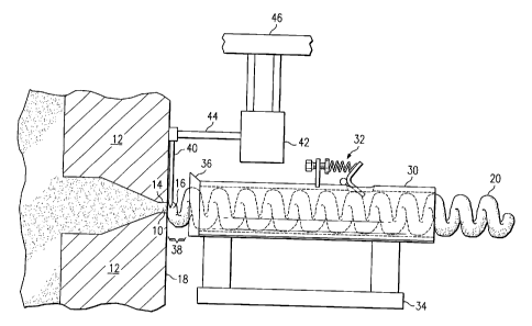
Figure 5 is an elevation view of one embodiment of the present invention.
Identical
reference numerals will be used to identify identical elements throughout all
of the drawings,
unless otherwise indicated. As with the prior art, the extrudate 16 exits an
orifice 14 in the
die 12. The cross-sectional diameter of the orifice 14 is dependent on the
specific dough
formulation, throughput rate, and desired rod (or other shape) diameter, but
is preferred in the
range of 1 mm to 14 mm. (The orifice 14 diameter is also dependent on the mean
particle
size of the corn meal or formula mix being extruded.)
If a curly puff extrudate 20 is desired, a tube 30 with a flapper 32 can be
used. A
flapper 32 puts pressure on the extrudate 16 exiting the orifice 14 so that
curls will form in
the extrudate 16. A tube positioning device 34 is used to position the tube 30
in front of or
away from the orifice 14. The tube positioning device 34 is capable of moving
the tube 30 in
any direction relative to the die 12. Examples of tube positioning devices are
electrical servo
motors, pneumatic actuators, hydraulic actuators, and mechanical screws. A
tube blade 36 is
also affixed to the end of the tube 30 closest to the die 12.
A nicking blade 40 is positioned flush with the die face 18 and either rotates
or
oscillates about a shaft 44. The nicking blade 40 and the shaft 44 are powered
by a motor 42,
which is connected to a blade positioning device 46. The blade positioning
device 46 is
capable of moving the motor 42, the shaft 44, and the nicking blade 40 in any
direction
relative to the die 12. Examples of blade positioning devices 46 are
electrical servo motors,
pneumatic actuators, hydraulic actuators, and mechanical screws. In order to
effectively nick
the extrudate 16 exiting the orifice 14, the nicking blade 40 is positioned
such that the end of
the nicking blade 40 only partially covers the orifice 14 when passing in
front of the orifice
14. Allowing the nicking blade 40 to completely cover the orifice 14 would
completely sever
the extrudate 16, which would not allow the extrudate 16 to remain connected
for additional
processing. It should be understood that the extent to which the nicking blade
40 covers the
CA 02501334 2005-04-06
WO 2004/035294 PCT/US2003/029780
orifice 14 determines the depth of the nick in the extrudate 16. Deeper nicks
will allow the
extrudate 16 to break more easily, a property referred to here as
breakability. Shallower
nicks will allow the extrudate 16 to stay connected more easily, a properly
referred to here as
connectivity. The amount of coverage over the orifice 14 is expressed as a
coverage
percentage that is equal to the length of the nicking blade 40 covering the
orifice 14 divided
by the orifice 14 cross-sectional diameter. The coverage percentage desired
will depend on
the type of viscous melt 10 and orifice 14 size. Coverage percentages of
eighty to ninety
percent have generally been found to be an acceptable balance between
breakability and
connectivity for the melt 10 and orifice 14 size described herein. If desired,
the rate at which
the nicking blade 40 nicks the extrudate 16 can be increased such that the
nicking blade 40
nicks the extrudate 16 faster than the extrudate 16 curls. When this is done
and the nicked
extrudate 16 is separated, smaller "C" shaped pieces of extrudate are formed.
Another factor affecting the nick size is the nicking blade 40 tip shape.
While pointed
nicking blades 40 are capable of nicking the extrudate 16, square edged
nicking blades 40
(i.e. where the edge of the nicking blade 40 contains two ninety degree
angles) have proven
more effective at creating uniform nicks in the curly puff extrudate 20.
During start up, the tube 30 is positioned away from the orifice 14 with the
tube blade
36 placed firmly against the die face 18. As the extruder starts and
approaches operating
parameters, it will extrude undesirable extrudate 16. The extruder also
extrudes an excess
amount of hot gasses, such as steam, from the orifice 14 during start up.
Steam and other hot
gasses tend to cause plugging in the tube 30. Positioning the tube 30 away
from the orifice
14 allows the undesired extrudate 16 to bypass the tube 30 and prevents the
undesired
extrudate 16, steam, and other hot gases from plugging the tube 30. The motor
42 is
generally not run during start up so that the start up extrudate 16 is not
nicked. Alternatively,
if the motor 42 is running, the blade positioning device 46 can position the
moving nicking
blade 40 such that the blade cutting radius 22 does not cover the orifice 14,
and the nicking
CA 02501334 2005-04-06
WO 2004/035294 PCT/US2003/029780
blade 40 will not nick the extrudate 16 nor interfere with the positioning of
the tube 30. In
this manner, the motor 42 and the nicking blade 40 can be brought up to
operating speed
without nicking the extrudate 16 or interfering with the positioning of the
tube 30. If desired,
the nicking blade 40 can be positioned by the blade positioning device 46 such
that it
completely cuts the extrudate 16 exiting the orifice l4. This method cuts the
extrudate 16
into smaller pieces and eliminates the need for a separating device.
Figures 6A-6C illustrate the process of starting up and operating one
embodiment of
the present invention. When the extruder reaches its operational parameters,
the tube
positioning device 34 positions the tube 30 so that the tube blade 36 is flush
with the die face
18 (See figure 6A). The tube positioning device 34 then quickly slides the
tube 30 across the
die face 18 until the orifice 14 is within the inside diameter of the tube 30
(See figure 6B).
When the tube blade 36 passes over the orifice 14, the tube blade 36 slices
off the old
extrudate 16 and allows the orifice 14 to extrude a new extrudate 16 into the
tube 30, where
the flapper 32 will contact the extrudate 16 and cause it to curl and form the
curly puff
extrudate 20.
After the tube positioning device 34 positions the tube 30 over the orifice
14, the tube
positioning device 34 moves the tube 30 away from the die 12 (See figure 6C).
Separating
the tube 30 from the die face 18 creates a gap 38. The gap 38 allows gasses
such as steam to
escape from the expanding extrudate 16 and allows the nicking blade 40 to
access the
extrudate 16 as it exits the orifice 14. Gap distances of 4-8 millimeters have
been found to be
a good balance between containing the curling extrudate inside the tube 30,
allowing the
nicking blade 40 access to the extrudate 16, and allowing sufficient release
of steam. It
should be understood that the gap 38 may vary depending on the pressure and
temperature of
the extrudate 16, the back pressure created by flapper 32, and the thickness
of the nicking
blade 40.
It should also be understood that multiple embodiments of the orifice 14, the
nicking
11
CA 02501334 2005-04-06
WO 2004/035294 PCT/US2003/029780
blade 40, and the tube 30 can be implemented on a single die 12. Figure 7 is
an illustration
of a die 12 with four such embodiments. The blade cutting radius 22 is defined
by the outer
reach of the nicking blade 40 and is shown only partially covering the orifice
14. The
position of the nicking blade 40 shown in figure 7 is preferable to other
configurations, such
S as one in which the shaft 44 is closer to the edge of the die face 18,
because the blade cutting
radius 22 does not extend beyond the perimeter of the die face 18. Keeping the
blade cutting
radius 22 within the perimeter of the die face 18 helps prevent injury to
people working in
close proximity to the extruder and the die 12. During operation of a die 12
with multiple
orifices 14, the extrudate 16 discharge rate may vary from one orifice 14 to
another. The
embodiment utilizing one nicking blade 40 for every orifice 14 is preferred
because it allows
an operator or automated controller to adjust the nicking blade 40 speed based
on the
extrudate 16 output rate and curling rate. By adjusting the speed of the
nicking blade 40 to
the output rate of the extrudate 16 of an individual orifice 14, the distance
between the nicks
on the extrudate 16 from each individual orifice 14 can be precisely
controlled and thus yield
curly puff extrudate 20 pieces of uniform length.
In certain situations, an embodiment utilizing a nicking blade 40 for every
orifice 14
may not be necessary or preferable. In these cases, a central nicking
apparatus 62, as shown
in figures 8A, 8B, and 8C, utilizing a central nicking apparatus positioning
device (not
shown), a blade positioning device 64, and at least one blade 60 can be
utilized. The central
nicking apparatus positioning device can move the central nicking apparatus 62
in any
direction relative to the die 12. Examples of central nicking apparatus
positioning devices 62
are electrical servo motors, pneumatic actuators, hydraulic actuators, and
mechanical screws.
A central nicking apparatus 62 like the one utilized in f gores 8A-8C can be
used to cut or
nick a plurality of orifices 14. Figures 8A-8C are illustrations of the
process of positioning
the central nicking apparatus 62 into the center of the die face 18 such that
the blades 60 of
the central nicking apparatus 62 are able to nick multiple orifices 14. In
Figure 8A, the
12
CA 02501334 2005-04-06
WO 2004/035294 PCT/US2003/029780
central nicking apparatus 62 is positioned close to the die face 18. A motor
(not shown)
powers the central nicking apparatus 62. As the central nicking device 62
begins to rotate,
the centrifugal force, caused by the rotation of the central nicking apparatus
62, forces opens
the blades 60. The blade positioning device 64 guides the blades 60 into
position such that
they will be parallel with the die face 18 when completely opened.
Alternatively, the blade
positioning device 64 can be actuated or otherwise controlled to force the
blades 60 into
position. In Figure 8B, the centrifugal force continues to expand the blades
60 and positions
them adjacent to the die face 18. The nicking apparatus 62 continues to rotate
so that the
blades 60 are moved into position and nick the extrudates 16 exiting the
orifices 14 (See
figure 8C). The blades 60 can also be extended far enough to completely sever
the
extrudates 16 exiting the orifices 14.
Refernng back to figure 5, after exiting the tube 30, the curly puff extrudate
20 is
generally transported to an oven for baking or a fryer for frying. The nicks
in curly puff
extrudate 20 are weaker than the rest of the curly puff extrudate 20 and,
consequently, the
1 S curly puff extrudate 20 breaks into individual curly puff extrudate 20
pieces with little or no
mechanical manipulation upon baking or frying. Figure 9 is an example of a
nicked curly
puff extrudate 20 piece that has separated in a flyer.
In some applications, it may be desirable to separate the individual curly
puff
extrudate 20 pieces prior to baking, frying, or some other processing. In that
case, there are a
variety of devices that can be used to separate the nicked curly puff
extrudate 20. One type
of separation device is a paddle wheel. Figures 10A and lOB are illustrations
of a paddle
wheel. In the embodiment disclosed in figures 10A and 10B, the curly puff
extrudate 20
exits the tube 30 and travels along a conveyer belt, which is parallel to the
shaft 70 of the
paddle wheel. The view in figures 10A and lOB is that of the curly puff
extrudate 20 being
conveyed out of the page towards the viewer. Each paddle wheel comprises a
shaft 70
connected to a motor (not shown). A plurality of paddles 72 are connected to
the shaft 70.
13
CA 02501334 2005-04-06
WO 2004/035294 PCT/US2003/029780
When the shaft 70 rotates, the paddles 72 come into contact the nicked curly
puff extrudate
20 (Figure 10A). By this point, the curly puff extrudate 20 has cooled
sufficiently to harden.
When the paddles 72 come into contact with the curly puff extrudate 20, the
nicked curly puff
extrudate 20 breaks at its weakest point, namely the nick. The individual
curly puff extrudate
20 pieces then fall into a capture bin underneath the paddle wheel (Figure
10B). A guide 74
keeps the curly puff extrudate 20 from repositioning itself out of the reach
of the paddles 72.
It should be realized that a paddle wheel is not the only device for
separating the
individual curly puff extrudate 20 pieces. A tumbler could be employed to
tumble the
unseparated curly puff extrudate 20 until the curly puff extrudate 20 pieces
break off. The
curly puff extrudate 20 pieces could then be removed from the tumbler. The
curly puff
extrudate 20 can also be separated on a vibrating conveyer or a conveyer
having steps or
direction changes that facilitate product separation. Persons skilled in the
art will also be
aware of various other devices for separating nicked curly puff extrudate 20.
While the present invention is disclosed in reference to curly puff extrudate
20, it
should be understood that the present invention could be employed with
cylindrical, uniquely
shaped, or any other type of extrudate 16. Additionally, the present invention
can be utilized
any time there is an need for cutting or nicking of a quasi-solid effluent
from any type of
process.
It should further be understood that more than one die 12 could be routed into
a single
tube 30. For example, a tube 30 can receive the extrudate 16 from two nearby
orifices 14.
Further, dies 12 producing any number of shapes, such as a star or square
cross section or
more complex shapes, such as a cactus or pepper shape, can be used with the
invention.
Any number of various types of extruders can be used with the invention,
including
twin screw and single screw extruders of any length and operating at a wide
range of
rotational speeds. Further, while the process has been described with regard
to a corn-based
product, it should be understood that the invention can be used with any puff
extrudate,
14
CA 02501334 2005-04-06
WO 2004/035294 PCT/US2003/029780
including products based primarily on wheat, rice, or other typical protein
sources or mixes
thereof. In fact, the invention could have applications in any field involving
extrusion of a
material that quickly goes through a glass transition stage after being
extruded through a die
orifice.
While the invention has been particularly shown and described with reference
to a
preferred embodiment, it will be understood by those skilled in the art that
various changes in
form and detail may be made therein without departing from the spirit and
scope of the
invention.