Note: Descriptions are shown in the official language in which they were submitted.
CA 02501676 2005-04-07
WO 2004/042144 PCT/FI2003/000810
METHOD AND ARRANGEMENT IN THE ON-DINE FINISHING OF THE PAPER
MACHINE
The invention relates to a method in the on-line finishing of
the paper machine, which includes at least the successive
finishing stages of precalendering and coating for the paper
web produced in the paper machine prior to reeling, in which
method a tail is formed from the paper web and this tail is
taken through the finishing stages in such a way that after the
1o tail threading procedure of the finishing stage the tail is
spread to form a fully wide paper web prior to forming and
taking a following tail to the following finishing stage. The
invention also relates to an arrangement in the on-line finish-
ing of the paper machine.
Today in the paper machines, the tendency is to locate the
finishing line immediately after the production line in order
to improve efficiency. This means that the paper web is immedi-
ately guided to the finishing process from the last section of
the production line without intermediate reeling and a sepa-
rately located finishing line. In other words, the paper web
runs at the production speed during finishing, and therefore
the term on-line finishing is also used. Normally finishing
includes coating of the paper. To produce an optimum quality
paper, the paper web is first precalendered in the finishing
process in order to ensure successful coating. Finally the
coated paper is often also calendered, which provides a good
surface smoothness and gloss, for example, to the coated paper.
3o The paper web is taken through the various finishing stages by
means of a tail formed out of the paper web. The tail also
proceeds at the production speed. Consequently, particularly
the speed differences between the various tail threading de-
vices often pause a tail threading failure. In addition, the
paper web is spread to the full width between the different
finishing stages prior to starting the following tail threading
CA 02501676 2005-04-07
WO 2004/042144 PCT/FI2003/000810
2
procedure. In present applications the tail must be taken, for
example, through the coating process and spread to the full
width before the paper web can be measured in respect of
precalendering. Consequently, controlling of the various fin-
s fishing stages is indefinite and awkward because the reliability
of the effect of the various finishing stages is uncertain.
Furthermore, in the situation described above, the coated paper
needs to be guided to broke treatment during the precalendering
adjustment. This increases the consumption of the coating
material and complicates the broke treatment.
Adjustment problems are also created in tail threading because
the tail needs to be guided for a long distance. This makes the
tail stretch and even break sometimes. Also the speed differ-
ences between the various tail threading devices and finishing
devices lead to tail breaking, in which case the tail threading
procedure must be usually started over again. Particularly in
the present paper machines the tail threading devices are
provided with speed sensors. In practice, however, controlling
2o the speed of the tail threading devices and a sufficiently
accurate speed measurement are difficult and sometimes even
impossible. With the further increasing speed, the problems
become even worse. Normally the tail is transferred through the
finishing stage by means of ropes. The finishing stage often
ends at a drying unit, which comprises dryer cylinders and a
dryer wire. When arriving at the drying unit with the carrier
rope system, the tail tends to move onto the dryer wire if even
a slight speed difference is present. In this situation the
tail normally breaks and tail threading fails. At the same
time, parts of the tail remain in the drying unit, which may
disturb the following tail threading attempts.
The tail is usually formed out of the paper web using water
cutters, which are arranged in connection with the drying
units. As the paper web must be cut against the dryer wire,
cuttings gradually block the dryer wire. Cuttings also spread
CA 02501676 2005-04-07
WO 2004/042144 PCT/FI2003/000810
3
into the drying unit and, in the worst case, to the entire
finishing process following it. This increases the likelihood
of web breaks and impairs the quality of the final product.
Furthermore, various kinds of cleaning devices are required.
US patent No. 4728396 sets forth a coater and a method for
using it. In this method the web is guided to the broke pit at
the full web width after unreeling the paper reel. A tail is
separated from the web, and this tail is guided to the coating
1o device. After spreading the tail, coating is started. At a web
break, the web is led to the broke pit at the processing speed
and the tail threading procedure is repeated. The equipment in
question is a so-called off-machine coater. In addition, there
is low potential in contributing to a successful tail thread
ing.
The object of the invention is to provide a novel method for
the on-line finishing in the paper machine, which is more
reliable than heretofore and minimizes production breaks.
Another object of the invention is to provide a novel arrange-
ment for the on-line finishing in the paper machine, which
avoids both tail breaks and unnecessary soiling of the finish-
ing processes. The characteristics of the method according to
this invention become evident from the appended claim 1. Corre-
spondingly, the characteristics of the arrangement according to
the invention become evident from the appended claim 7. In the
method according to the invention, each finishing stage is used
independently. This enables an optimum control of each finish-
ing stage minimizing the production breaks. Correspondingly,
3o the final result of each finishing stage can be determined
prior to moving to the following finishing stage. This facili-
tates the control of the paper machine and reduces the amount
of broke. In addition, with the arrangement according to the
invention, the tail can be kept under a better control than
heretofore. At the same time, the likelihood of a successful
tail threading is higher than before. In addition, the arrange-
CA 02501676 2005-04-07
WO 2004/042144 PCT/FI2003/000810
4
ment according to the invention is grouped better than earlier
and its discontinuation points are as few as possible. The
arrangement also allows to cut the paper web without soiling
the finishing stage. At the same time, broke treatment can be
easily arranged at the end of the finishing stage.
The invention is described below in detail by making reference
to the enclosed drawings, which illustrate some of the embodi-
ments of the invention, in which
Figure 1 shows a skeleton drawing of the arrangement accord-
ing to the invention, I
Figure 2a shows a variation of one finishing stage of the
arrangement illustrated in Figure 1,
Figure ~b shows another variation of one finishing stage of
the arrangement illustrated in Figure 1,
Figure 3 is an enlarged view of a part of the whole of the
arrangement according to' the invention,
Figure 4a is a flow chart, covering one finishinct stage, il-
lustrating the operation of the arrangement accord-
ing to the invention,
Figure 4b is a skeleton drawing illustrating the travel of the
paper web in one finishing stage of the arrangement
according to the invention.
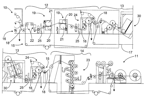
Figure 1 is a skeleton drawing of the arrangement according to
the invention, which is specifically intended for the on-line
finishing in the paper machine. In Figure 1 the actual produc-
tion stages of the paper machine end at the dryer section 10,
3o from which the paper web produced with the paper machine is run
down to broke treatment. Similar points, at which the paper web
is run down, are illustrated in the drawings with downward
pointing arrows. Broke treatment equipment is not shown in the
drawings. At the end of the finishing process, the paper web is
reeled up with the reel 11. Prior to reeling the finishing
process includes the successive finishing stages of at least
CA 02501676 2005-04-07
WO 2004/042144 PCT/FI2003/000810
precalendering 12 and coating 13. Here coating 13 is addition-
ally followed by calendering 14. The finishing stages 12 - 14
also include the tail threading equipment 15 for taking the
tail through the finishing stages 12 - 14. To form the tail out
5 of the fully wide paper web, the tail threading equipment 15
also includes cutting equipment 16. Here the tail threading
equipment 15 mainly consists of carrier rope systems 17, which
are used to carry the tail onwards. The tail threading equip-
ment 15 also comprises, mainly between the various finishing
stages, vacuum belt conveyors 18, which are used to transfer
the tail, formed out of the paper to be run down, to the tail
threading equipment of the following finishing stage - in this
case to a carrier rope system. For clarity, neither the paper
web nor the tail is shown in figures. In each finishing stage
the carrier rope systems essentially pass over the same route
as the paper web does in the production.
In the application displayed precalendering 12 consists of two
successive so-called soft calendars 19. Their calendering nips
2o are composed of a hard roll 20 and a softer counter roll 21. In
the successive soft calendars 19 the softer counter roll 21 is
alternately on the different sides of the paper web, thus
precalendering the two sides of the paper web in turn. Prior to
the soft calendars 19, on both sides, there is additionally
moistening equipment 22, which can be used to adjust the mois-
ture profile of the paper web when required. Coating also takes
place in the nip, which is followed by the drying equipment 30.
Finally, there is a so-called hard calendar 23, composed of
several rolls placed on top of each other between which several
3o nips are formed. From the hard calendar 23 the coated and
calendered paper web is led to the reel 11, which shares a
carrier rope system with the hard calendar 23. The equipment
used in various finishing stages can vary between different
applications. The same reference numbers are used for function
ally similar parts.
CA 02501676 2005-04-07
WO 2004/042144 PCT/FI2003/000810
6
According to the invention, at the end of each finishing stage
there is a draw point forming one contact for tensioning and
holding the paper web in the finishing stage concerned. The
draw point is generally referred to with number 24. Due to the
draw point, the paper web is kept under control for the entire
duration of the finishing stage. A single contact of the draw
point is particularly important as regards the tail. In prac-
tice, the draw point terminates the finishing stage and the
carrier rope system used as the tail threading device is guided
through it. Due to the single contact, the speed difference
between the tail threading device and the draw point, as well
as a possible tail break caused by it, have no importance,
because the tail is run down to broke treatment immediately
after the draw point. In other words, it may be even desirable
that the tail is transferred to the draw point from the tail
threading device, the tail thus being immediately under con-
trol. Consequently, also the paper web can be spread earlier
than before, which shortens the production break.
2o The arrangement preferably also includes measuring elements 25
arranged in the finishing stage 12 - 14 prior to the draw point
24 for determining the desired properties of the paper web. The
purpose of the measuring elements is discussed in more detail
in connection with the description of the method according to
the invention.
Figure 1 shows an arrangement according to the invention, in
which both the draw point 24 placed after precalendering 12 and
the one after coating 13 are similar. Figures 2a and 2b show
3o variations of the draw point after precalendering. The point in
question is circled with a dot-and-dash line in Figure 1.
Generally the draw point forming a single contact is arranged
as a roll nip or a fabric transfer between two rolls. In Figure
2a one roll in the roll nip is a counter roll 21 adapted for
precalendering 12, while the other one is a separate auxiliary
roll 26. This ensures that the total length of the finishing
CA 02501676 2005-04-07
WO 2004/042144 PCT/FI2003/000810
7
stage remains as short as possible.~On the other hand, an extra
auxiliary roll complicates the design of the precalender and
hinders its guiding especially in tail threading. Figure 2b
illustrates a third application of the draw point 24, in which
both the rolls of the roll nip are auxiliary rolls 27. The
auxiliary rolls 27 are additionally arranged separately from
the equipment included in the finishing stage. In this case,
precalendering remains unchanged, but an extra pair of rolls
increases the length of the finishing stage. In both the appli-
l0 cations set forth above the problem is additionally the dis
tance between the cutting equipment and the following finishing
stage, i.e. coating here. Furthermore, drying of the paper web
is impossible. On the other hand, in the application of Figure
2b the cutting equipment 16 could also be located within the
open draw of the paper web.
Both of these problems are avoided with the draw points 24
illustrated in Figures 1 and 3, in which the fabric transfer is
formed between one dryer cylinder 2~ and a dryer wire 29 ar-
ranged to contact it. In this way, a drying effect is provided
to the paper web at the draw point and the paper web can be
simultaneously drawn more efficiently than before. The tail is
also reliably transferred to the influence area of the dryer
wire so that the tail can be quickly taken under control before
it is run down to broke treatment. In this application. te~~.
the speed difference between the dryer wire and the carrier
rope system has no significance, yet, in practice, it is at-
tempted to keep it as small as possible. The solution also
provides an advantageous tail formation. The only drawback is
mainly the increased length of the finishing stage. On the
other hand, a single-cylinder draw point is remarkably shorter
than the known three-cylinder drying equipment. Furthermore, in
the embodiment set forth, the paper web can be dried also after
precalendering.
CA 02501676 2005-04-07
WO 2004/042144 PCT/FI2003/000810
8
Figure 3 is a more detailed illustration of the single-cylinder
application. Even a small wrap angle of the dryer wire 29
provides a reliable tail seizure and an efficient paper web
draw. According to the invention the cutting equipment 16 is
adapted to cut the tail from the~paper web within its open
draw. This becomes evident specifically in Figure 3. Here the
cutting equipment 16 is composed of water cutters, which are
arranged prior to the actual draw point. This prevents access
of cuttings to the production process or onto the dryer wire,
l0 and it is easy to guide away the cuttings from the cutting
point in a controlled way. In addition, the cutting equipment
is placed advantageously near to the run-down position, which
minimizes disturbances in tail threading and spreading of
cuttings to the process.
Normally the paper web is spread to the full width after tail
threading prior to forming and taking the following tail to the
following finishing stage. According to the invention, prior to
starting the tail threading procedure of the next finishing
2o stage and forming the tail, the finishing stage in question is
surprisingly set to the production settings while the paper web
is spread in its full width. This facilitates the total control
of the finishing stages. A reliable broke treatment is provided
with the above described draw point, which is used to tension
and hold the paper web in the finishing stage. This also en-
sures that the tension of the paper web is always appropriate
particularly when using a single-cylinder draw point.
Draw points placed at the ends of the finishing stages also
3o enable the determination of the paper web properties in each
finishing stage already prior to starting the next tail thread-
ing. These properties are determined at the draw point and/or
prior to it. To achieve this, the arrangement includes measur-
ing elements 25 known as such, which are used to determine for
example the moisture content of the paper web as well as poros-
ity, gloss and other surface properties. Based on the specified
CA 02501676 2005-04-07
WO 2004/042144 PCT/FI2003/000810
9
paper properties each finishing stage is then easy to adjust to
the production settings. In this way, considering the whole,
the control of the finishing stages is less complicated with a
smaller broke amount and coating material consumption than
heretofore.
Adjustments of the finishing stages particularly influence the
properties of the paper web and the final product made of it.
Furthermore, according to the invention, the properties of the
l0 tail in the tail formation are changed. This ensures a success-
ful tail threading. In practice, the moisture content of the
tail is changed using for example special moistening nozzles.
Figure 4a shows a flow chart in which the operation of the
arrangement according to the invention is illustrated for one
finishing stage, simplified for one stage. The stage starts
with the reception of the tail formed in the previous stage.
The tail threading procedure is repeated until it is success-
ful, after which the paper web is spread to the full width. The
2o tail transferred through the stage is run down to broke treat-
ment at the end of the stage. According to the invention, the
stage is thus set to the production settings after spreading
and the treated paper web is measured. The determination of the
quality of the paper web takes place based on these measure-
ments. In case there are deviations in the quality, the stage
will be adjusted. Once the desired paper web quality is
achieved, a tail is formed and guided to the following stage.
Figure 4b shows the travel of the paper web in a stage, which
is here coating 13. The use of the measuring elements 25 is
possible at the draw point 24 according to the invention, which
keeps the paper web under control at all times. Here the paper
web has passed the stage and has already been spread to the
full width. In practice, this spreading takes place in the
previous stage. In the situation illustrated in Figure 4b, the
cutting equipment 16 is used to form a tail from the paper web
CA 02501676 2005-04-07
WO 2004/042144 PCT/FI2003/000810
whose quality has been proven good. The rest of the paper web
is then run down to broke treatment after the draw point 24.
Between the stages the tail is transferred using for example
the vacuum belt conveyors 18.
5
In the arrangement according to the invention, the various tail
threading procedures are separate and distinct entities, corre-
sponding to the different finishing stages. Each tail threading
procedure includes few disturbance points and the tail is kept
1o under control at all times. Due to the draw point according to
the invention, the speed difference between the various tail
threading devices and the draw point has no importance. Due to
the draw point, the properties of the paper web can be deter-
mined in each finishing stage prior to the following finishing
stage. In this way, using the method according to the inven-
tion, the production process can be appropriately adjusted in
a simple and accurate manner. This saves both time and energy.
At the same time, the finishing stage is kept clean, which
reduces the need for cleaning equipment. With the method and
arrangement according to the invention it is possible to opti-
mize each finishing stage and hence also the paper properties
prior to starting the following tail threading. In practice,
precalendering and coating can be optimized prior to the start
of the actual calendering, which also makes the entire finish-~
ing process remarkably more stable than heretofore.